Automation, Control and Intelligent Systems 2014; 2(6-1): 1-9 Published online November 20, 2014 (http://www.sciencepublishinggroup.com/j/acis) doi: 10.11648/j.acis.s.2014020601.11 ISSN: 2328-5583 (Print); ISSN: 2328-5591 (Online)
Speed control of a DC motor using Controllers Md Akram Ahmad1, Kamal Kishor2, Pankaj Rai3 1
Electronics and Communication Engineering Department, Maryland Institute of Technology and Management, Jamshedpur, India Electronics and Communication Engineering Department, Ramgovind Institute of Technology, Koderma, India 3 Electrical Engineering Department, BIT Sindri, Dhanbad, India 2
Email address:
[email protected] (Md. Akram Ahmad),
[email protected] (Kamal Kishor),
[email protected] (Dr. Pankaj Rai)
To cite this article: Md Akram Ahmad, Kamal Kishor, Pankaj Rai. Speed Control of a DC Motor Using Controllers. Automation, Control and Intelligent Systems. Special Issue: Impact of Gesture Recognition in the Technological Era. Vol. 2, No. 6-1, 2014, pp. 1-9. doi: 10.11648/j.acis.s.2014020601.11
Abstract: This paper describes the speed control of a DC shunt motor using conventional controllers (PID, IMC) and Fuzzy Logic controller based on Matlab Simulation program. A mathematical model of the process has been developed using real plant data and then conventional controllers and Fuzzy logic controller has been designed. A comparative analysis of performance evaluation of all controllers has been done. Keywords: PID Controller, IMC, FLC, DC Motor
1. Introduction DC motors are widely used in industrial applications, robot manipulators and home appliances, because of their high reliability, flexibility and low cost, where speed and position control of motor are required. This paper deals with the performance evaluation of different types of conventional controllers and intelligent controller implemented with a clear objective to control the speed of separately excited DC motor. PID controllers are commonly used for motor control applications because of their simple structures and intuitionally comprehensible control algorithms. Controller parameters are generally tuned using Ziegler-Nichols frequency response method [1]. Ziegler-Nichols frequency response method is usually used to adjust the parameters of the PID controllers. However, it is needed to get the system into the oscillation mode to realize the tuning procedure. But it’s not always possible to get most of the technological plants into oscillation [2]. In process control, model based control systems are mainly used to get the desired set points and reject small external disturbances. The internal model control (IMC) design is based on the fact that control system contains some representation of the process to be controlled then a perfect control can be achieved. So, if the control architecture has been developed based on the exact model of the process then perfect control is mathematically possible [3]. Fuzzy logic control (FLC) is one of the most successful
applications of fuzzy set theory, introduced by L.A Zadeh in 1973 and applied (Mamdani 1974) in an attempt to control system that are structurally difficult to model. Since then, FLC has been an extremely active and fruitful research area with many industrial applications reported [4]. In the last three decades, FLC has evolved as an alternative or complementary to the conventional control strategies in various engineering areas. Analysis and control of complex, nonlinear and/or timevarying systems is a challenging task using conventional methods because of uncertainties. Fuzzy set theory [5] which led to a new control method called Fuzzy Control which is able to cope with system uncertainties. One of the most important advantages of fuzzy control is that it can be successfully applied to control nonlinear complex systems using an operator experiences or control engineering knowledge without any mathematical model of the plant [6].
2. DC Motor Direct current (DC) motors convert electrical energy into mechanical energy through the interaction of two magnetic fields. One field is produced by a magnet of poles assembly, the other field is produced by an electrical current flowing in the motor windings. These two fields result in a torque which tends to rotate the rotor.
2
Md Akram Ahmad et al.: Speed Control of a DC Motor Using Controllers
Based on the data book, the transfer function is as &
' &
$
(11)
&+ , $&,$/./$
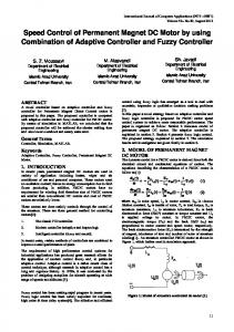
3. Proportional-Integral-Derivative (PID) Controller Figure 1. DC shunt motor model.
The armature voltage equation is given by: V t
R I
t
L .
E t
(1)
Equation for back emf of motor will be K ω t
E t
(2)
Now the torque balance equation will be given by: T
t
T
t
K. I
t
t
K. I t
L . J
R .I s
>? @
K ω t Bω t
K. I s
L .I s Jω s
ω s
!"
#L . Js $
(5) (6)
K ω s
Bω s
R .J
L .B s
(7) (8)
K .K %
' &
(
)* &+ , )- , * &, ( (. , -
:9
=
(12)
(10)
This is the transfer function of the DC motor. Consider the following values for the physical parameters [7,8] Armature inductance (L ) = 0.5 H Armature resistance (R ) = 1Ω Armature voltage (V ) = 200 V Mechanical inertia (J) = 0.01 Kg.m2 Friction coefficient (B) = 0.1 N-m/rad/sec Back emf constant K = 0.01 V/rad/sec Motor torque constant K = 0.01N.m/A Rated speed = 1450 rpm
A B
C B
12 1
56 B