Results are presented for the optimization of Lamb wave techniques applied to quasi-isotropic ..... Taylor & Francis, Blacksburg, VA, 1999. 22. Kessler S.S. ...
Optimization of Lamb Wave Methods for Damage Detection in Composite Materials Seth S. Kessler, S. Mark Spearing and Constantinos Soutis Technology Laboratory for Advanced Composites Department of Aeronautics and Astronautics Massachusetts Institute of Technology
SHM-2001
ABSTRACT1 Cost-effective and reliable damage detection is critical for the utilization of composite materials. This paper presents part of an experimental and analytical survey of candidate methods for in-situ damage detection of composite materials. Results are presented for the optimization of Lamb wave techniques applied to quasi-isotropic graphite/epoxy specimens containing representative damage modes. Linear wave scans were performed on narrow laminated coupons and sandwich beams by monitoring the transmitted waves with piezoceramic sensors (PZT). Optimal actuator and sensor configurations were devised through experimentation, and various types of driving signals were explored. Lamb wave techniques have been proven to provide more information about the presence of damage and its severity than previously tested methods, and may prove suitable for structural health monitoring applications since they travel long distances and can be applied with conformable piezoelectric actuators and sensors that require little power.
INTRODUCTION Structural Health Monitoring (SHM) has been defined in the literature as the “acquisition, validation and analysis of technical data to facilitate life-cycle management decisions.” [1] More generally, SHM denotes a system with the ability to detect and interpret adverse “changes” in a structure in order to improve reliability and reduce life-cycle costs. The greatest challenge in designing a SHM system is knowing what “changes” to look for and how to identify them. The Seth S. Kessler, Massachusetts Institute of Technology, Cambridge, MA 02139, USA S. Mark Spearing, Massachusetts Institute of Technology, Cambridge, MA 02139, USA Constantinos Soutis, Imperial College, London SW7 2BY, UK
characteristics of damage in a particular structure plays a key role in defining the architecture of the SHM system. The resulting “changes,” or damage signature, will dictate the type of sensors that are required, which in-turn determines the requirements for the rest of the components in the system. The present research project focuses on the relationship between various sensors and their ability to detect “changes” in a structure’s behavior. Several techniques have been researched for detecting damage in composite materials, however Lamb wave methods have recently re-emerged as a reliable way to locate damage in these materials [2-4]. These techniques have been implemented in a variety of fashions in the literature, including the use of separate actuators and sensors to monitor transmitted waves and/or reflected waves, and multipurpose patches which both actuate and sense. Each of these techniques offers their own unique advantages in detecting certain types of damage with various levels of analytical complexity. Perhaps the earliest recognition of Lamb waves as a means of damage detection came in 1960 by Worlton of the General Electric Company [5]. His report investigated the dispersion curves of aluminum and zirconium to describe analytically the characteristics of the various modes that would pertain to nondestructive testing applications. During the late 1980’s and early 1990’s work began on the application of Lamb waves to composite materials. Research conducted at NASA by Saravanos demonstrated, both analytically and experimentally, the possibility of detecting delamination in composite beams using Lamb waves [6, 7]. Similar conclusions were drawn by Percival and Birt at the Defense & Evaluation Research Agency, UK, who began focusing their work on the two fundamental Lamb wave modes, which will be described further in the following section [8, 9]. Work was also performed on composite sandwich plates subjected to impact damage by Osmont and Rose [10, 11]. The most successful work to date of using Lamb waves for damage detection has been performed by two separate groups at Imperial College. Since the mid-1990’s, Cawley’s group has been working to optimize the generation of directional Lamb waves [12, 13]. To allow the implementation of Lamb waves on a real structure, they have been developing flexible, cheap Polyvinylidenedifloride (PVDF) transducers in order to both generate and detect waves. Their work uses interdigital transducer leads to generate highly focused and directional waves without higher mode interference, and they have inspected various metallic specimens with encouraging results. Soutis’s group in the Aeronautics department has focused more on the sensor placement and signal processing issues [14]. They have chosen to use Lead-Zirconate-Titanate (PZT) actuators and sensors over PVDF since they require a factor of ten less voltage to generate Lamb waves, however they are not conformabe. The most complete work from this group can be found in Valdez’s PhD thesis [15]. During the course of his work he performed many experiments on quasi-isotropic graphite/epoxy composite specimens, pulsing them with Lamb waves in various configurations to detect delaminations. He also simulated the propagation of Lamb waves in plates using a finite element code. Much of the research presented in this paper follows Valdez’s work, extending it to various other types of damage, to sandwich structures, and an attempt to optimize the testing procedure and setup. The following section will discuss the fundamentals and mathematics of Lamb wave propagation.
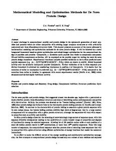
DESCRIPTION OF LAMB WAVES Lamb waves are a form of elastic perturbation that can propagate in a solid plate with free boundaries, first described in theory by Horace Lamb in 1917 [1618]. There are two groups of waves, symmetric and anti-symmetric as seen in Figure 1, that satisfies the wave equation for this problem. The present work utilizes PZT piezoelectric patches to excite the first anti-symmetric Lamb wave (A0 mode). This wave was chosen since it can propagate long distances with little dispersion, and no higher modes are present to clutter the resulting response waves [16]. The fundamental way to describe the propagation of Lamb waves in a material is with their dispersion curves, which plots the phase and group velocities versus the excitation frequency (often shown as a product with thickness). These curves are derived as solutions to the wave equation for the Lamb wave, and are often describe in terms of Lamé’s constants. This equality must be solved numerically for a given set of constant material properties. Examples of dispersion curves can be found in several places in the literature, and will not be focused on in this paper [12-16].
OPTIMIZATION Optimization Procedure There is currently no standard or even a best-practice precedent for damage detection via Lamb wave testing. Several procedures have been developed in the literature, each with valuable characteristics. The goal of the present research was to determine experimentally and analytically the effects of various parameters on the sensitivity of damage detection. These parameters can be divided into three categories: actuator and sensor geometry, actuation pulse, and specimen properties. The effects of the PZT dimensions were not explored thoroughly in this research however, since much literature exists on this topic [19, 20]. The second set of variables explored was the actuation pulse parameters. These included the pulse shape, amplitude, frequency and number of cycles to be sent during each pulse period. These parameters were varied experimentally on a test specimen to observe their effects on the generated waves. Two piezoceramic patches were attached to either end of the specimen, one connected to an arbitrary function generator and the other to an oscilloscope as seen in Figure 2. For each pulse shape, the various parameters were changed independently as the transmitted wave was observed in the oscilloscope. The power-spectral-densities (PSD) of the shapes that produced the best results were then compared in Matlab. Similarly the effect of the number of cycles per period for the different shaped signals was observed in the PSD plots by comparing the energy dedicated to the principal driving frequency. The more energy dedicated to the desired driving frequency, the stronger the Lamb wave and the more accurate the wave speed calculation, and hence the more sensitive and reliable the damage detection capability. The final component of the optimization analysis mathematically quantified the significance of the specimens’ geometric and material properties. Dispersion curves for each proposed specimen configuration
were created, and the material constants for the composite laminates to be analyzed were calculated by classical laminated plate theory, and then inputted into the model [21]. Using the same model code, each material constant such as the tensile modulus, Poisson ratio and density were modified independently, and the effect on the dispersion curves was documented. From the optimization experiments and analysis, an effective test procedure was determined. Results PULSE FREQUENCY The dispersion curves show the relationship between the phase velocity and pulse frequency. At lower frequencies, fewer Lamb modes are excited so the response signal is more distinguishable, and the velocity is slower so there is more time separating the sent and received signals making any changes more distinguishable. At these lower frequencies however, the dispersion curves have steep slopes and thus are very sensitive to small variations in frequency making it difficult to predict the time of flight. At higher frequencies, when more modes are present, the slope then tends to flatten out with the consequence of a shorter wave pulse carrying less or more compressed information of damage. The actuating frequencies were selected based on their slope and location on the dispersion curves and experimentation using a function generator to determine the maximum response amplitude for a range of candidate frequencies. PULSE AMPLITUDE Increasing the driving voltage proportionately increases the magnitude of the Lamb wave strain. Driving the actuating PZT at 5-10V produced a 10-25 mV response due to the Lamb wave at the sensing PZT, with 1-5 mV of static noise. Increasing the amplitude also increases the signal to noise ratio to yield a clearer signal. Higher voltage however also tended to increase the drift in the signal, which deteriorated the resolution capabilities of the data acquisition system. Another consideration is that a potential SHM system should be as low power as possible. NUMBER OF CYCLES The number of cycles of a periodic function to actuate with is one of the more complicated decisions to be made for Lamb wave techniques. The FFT of a continuous sine wave yields a single peak at the driving frequency, however for a few finite cycles, the FFT appears as a Gaussian curve with its peak at the driving frequency. Thus, the more waves sent into a driving pulse, the narrower the bandwidth and the less dispersion. The problem in a short specimen though, is the more waves in the pulse, the less time between last sent signal and the first reflected one, so the response is more difficult to interpret. An appropriate number of cycles can be determined by the maximum number of waves that can be sent in the time it takes for the lead wave to travel to the sensing PZT patch. It is also convenient to use intervals of half cycles so that the sent sinusoidal pulse becomes symmetric.
PULSE SHAPE Of the signal shapes that were tested, pure sinusoidal shapes appear to excite Lamb wave harmonics the most efficiently, since they are periodic, smooth and have comparatively quick rise times to their peak amplitude as compared to a parabolic shape. A Hanning window helps to narrow the bandwidth further to focus the maximum amount of energy into the desired actuating frequency with the least “spill-over” from neighboring frequencies. MATERIAL PROPERTIES To first order, the wave velocity increases with the square root of the modulus, i.e. an increase in modulus slightly speeds the wave. An increase in the density would have the opposite effect however by slowing wave velocity. The effect of the Poisson’s ratio is probably the most complicated, as it appears in the most terms, however to first order, small changes seem to have little to no effect on the wave velocity. The most straightforward parameter is the thickness of the specimen, which has a linear relationship with the Lamb wave velocity. The thicker the specimen the quicker the speed and the higher the dispersion rate for a given driving frequency. Discussion Two important sets of results were obtained from the optimization study. The first set was the analytical trade studies performed to predict the effectiveness of Lamb wave methods in different applications. Using the formulations derived by Lamb, the effects of material constants and specimen geometry were determined. By entering the properties for a particular application the resulting dispersion curves provide a range of wave velocities for the A0 mode driven at different frequencies. If the characteristic wave velocity for a material is too fast to be acquired, then this method is not suitable. Also, with knowledge of the effects of various damage types on the stiffness of a particular material, the resolution of change for the resultant signal, or “observeability” can be predicted in order to determine the detection limitations with respect to flaw size for a given data acquisition capability. The second result was the determination of the optimal test parameters to be applied for a particular material. Using the dispersion curves for a material, a range of driving frequencies can be selected based upon regions of smallest slope and driving capabilities while remaining below frequencies that would generate higher order waves. Next, experimentally these frequencies can be tuned to find the optimal frequency in that range to produce the largest amplitude Lamb wave. There is then a trade between number of waves that can be sent in a pulse and the distance from features in the structure. For the experiments presented in this paper, 15 kHz was the driving frequency for the thin laminates and 50 kHz for the sandwich beam specimen, using a 5V signal of 3.5 sine waves. These sets of tools could be used in tandem by an engineer developing a SHM system to decide if the Lamb wave method would provide satisfying results for their application, and to determine the appropriate driving parameters to obtain the best damage detection resolution.
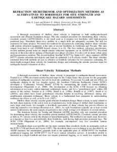
EXPERIMENTAL PROCEDURE Experiments were conducted on narrow coupons with various forms of representative damage, which were manufactured during previous research that explored frequency response methods [22]. The specimens were 25 x 5 cm rectangular [90/±45/0]s laminates of the AS4/3501-6 graphite/epoxy system. Three PZT patches (2 x 0.5 cm) were affixed to each specimen using a thermoplastic tape, as shown in Figure 2, for actuation and sensing. To stimulate an A0 mode Lamb wave, single pulse of the optimal signal, seen in Figure 3, was sent to the driving PZT patch. Concurrently, the strain-induced voltages of the other two patches were recorded and plotted as time traces, as seen in Figure 4. Subsequently, a wavelet decomposition was performed to separate the data into its various frequency components, and by plotting the magnitude of the wavelet coefficient at the peak driving frequency, the energy remaining from the actuated signal could be compared [23]. Analogous experiments were performed on sandwich coupons with various cores, by exciting the Lamb waves at 50 kHz. A final “blind test” of the proposed damage detection method was performed by testing two control specimens alongside one with an artificial flaw that was indistinguishable from the controls by sight, the results of which can be seen in Figure 5. The results from all tests clearly show the presence of damage in all of the non-control specimens. There was a high degree of correlation in the time traces between the control specimens, and for the damaged specimens the frequency often remained the same, however there was a large reduction in amplitude and change in phase. The clearest results were obtained by regarding the wavelet decomposition plots, in which the control specimens retained over twice as much energy at the peak frequency as compared to all of the damaged specimens. Probably the most significant result was from the “blind test.” By comparing the four wavelet coefficient plots in Figure 5, one can easily deduce that the two control specimens are the ones with much more energy in the transmitted signals, while the third specimen (Control C) obviously has the flaw that reduces energy to a similar level to that of the known delaminated specimen. This test serves as a true testament to the viability of the Lamb Wave method being able to detect damage in at least simple structures.
IMPLEMENTATION OF LAMB WAVE TECHNIQUES IN SHM SYSTEM Lamb wave techniques have good potential for implementation in a SHM system. These methods have the potential to provide useful information about the presence, location, type, size and extent of damage in composite materials, and can be applied to a structure with conformable piezoelectric devices. The major disadvantage of this method is that it is active; it requires a voltage supply and function generating signal to be supplied. This can be complicated in a large structure, especially if the SHM system is to be implemented wirelessly; it has been suggested in the literature however that PZT can be actuated remotely using radio frequency waves [15]. Another difficult requirement is the high data acquisition rate needed to gain useful signal resolution. If a system is sampling at 0.5 MHz
from several sensors, a large volume of data will accumulate quickly, implying the need for local processing. The data acquisition capabilities dictate the limitations of flaw size able to be resolved by a system using this method. In order to conserve power and data storage space, the Lamb wave method should most likely be placed into a SHM system in conjunction with another passive detection method, such as a frequency response method. The piezoelectric patches used to actuate the Lamb waves could passively record frequency response data until a certain threshold of change is surpassed, and then trigger the generation of Lamb waves to gain more specific data about the damaged region. Three to four piezoelectric multifunctioning actuator/sensor patches would be placed in the same vicinity in order to be able to triangulate damage location based upon reciprocal times of flight and reflected waves. The separation between sensing patches would depend on several parameters such as the material properties, damping characteristics and curvature of the structure, which for flat areas could be as large as 2 meters apart [15]. The detailed specifications of the Lamb wave method to be used for a particular application would be designed by the procedure described in the previous optimization section. Another useful detection capability arises from the fact that two different optimal driving frequencies were necessary for the thin laminates and the beam structures. This offers the possibility of having the ability to differentiate between damage within the laminate versus damage between the laminate and the core by discretely driving at two different frequencies. This procedure was not explored during the present research, however preliminary experimentation indicates that the potential of this procedure working exists.
CONCLUSIONS This paper has explored the optimization and application of Lamb wave methods to damage detection in composite materials. Several mathematical trade studies were preformed to observe the effect of various material constants and actuator driving parameters. Using these tools, an experimental configuration was selected, and several narrow graphite/epoxy coupon and beam specimens were tested with various forms of damage. These tests demonstrated the feasibility of detecting several types of flaws in representative composite structures, and this method was validated successfully by a “blind test” of several beam specimens. Lamb wave techniques have the potential to provide more information than previously tested methods such as frequency response methods since they are more sensitive to the local effects of damage to a material than the global response of a structure. The disadvantage of Lamb wave methods is that they require an active driving mechanism to propagate the waves, and the resulting data can be more complicated to interpret than many other techniques. Overall, Lamb wave methods have been found to be effective for the in-situ determination of the presence and severity of damage in composite materials. Future experimentation will be aimed at testing built up structures using this technique, and the use of a combined actuator and sensor. Structural heath monitoring systems will be an important component in future designs of air and spacecraft to increase the feasibility of their missions, and Lamb wave techniques will likely play a role in these systems.
REFERENCES 1.
2. 3. 4.
5. 6.
7.
8. 9. 10. 11.
12. 13.
14.
15. 16. 17. 18. 19. 20. 21. 22.
23.
Hall S.R. “The Effective Management and Use of Structural Health Data.” Proceedings of the 2 nd International Workshop on Structural Health Monitoring, Stanford, CA September 8-10 1999, 265-275. Bar-Cohen Y. “NDE of Fiber Reinforced Composite Materials —A Review.” Materials Evaluation, v.44, 1986, 446-454. Chang FK. “Structural Health Monitoring: A Summary Report.” Proceedings of the 2nd International Workshop on Structural Health Monitoring, Stanford, CA, September 8-10, 1999. Giurgiutiu V., Jingjing B. and W. Zhao “Active Sensor Wave Propagation Health Monitoring of Bean and Plate Structures.” Proceedings of the SPIE International Symposium on Smart Structures and Material, Newport Beach, Ca, March 5-8 2001. Worlton D.C. “Experimental Confirmation of Lamb Waves at Megacycle Frequencies.” Journal of Applied Physics, v.32, 1961, 967-971. Saravanos D.A. and P.R. Heyliger. “Coupled Layerwise Analysis of Composite Beans with Embedded Piezoelectric Sensors and Actuators.” Journal of Intelligent Material Systems and Structures, v.6, 1995, 350-362. Saravanos D.A., Birman V. and D.A. Hopkins. “Detection of Delaminations in Composite Beams using Piezoelectric Sensors.” Proceedings of the 35th Structures, Structural Dynamics and Materials Conference of the AIAA, 1994. Percival W.J. and E.A. Birt. “A Study of Lamb Wave Propagation in Carbon-Fibre Composites.” Insight: Non-Destructive Testing and Condition Monitoring, v.39, 1997, 728-735. Birt E.A. “Damage Detection in Carbon-Fibre Composites using ultrasonic Lamb Waves.” Insight: Non-Destructive Testing and Condition Monitoring, v.40, 1998, 335-339. Rose J.L., Hay T. and V.S. Agarwala. “Skin to Honeycomb Core Delamination Detection with Guided Waves.” 4 th Joint DOD/FAA/NASA Conference on Aging Aircraft, 2000. Osmont D., Devillers D. and F. Taillade. “A Piezoelectric Based healther Monitoring System for Sandwich Plates Submitted to Damaging Impacts.” European Congress on Computational Methods in Applied Sciences and Engineering, 2000. Monkhouse R.S.C., Wilcox P.D. and P. Cawley. “Flexible Interdigital PVDF Transducers for the Generation of Lamb Waves in Structures.” Ultrasonics, v.35, 1997, 489-498. Monkhouse R.S.C., Wilcox P.W., Lowe M.J.S., Dalton R.P. and P. Cawley. “The Rapid Monitoring of Structures using Interdigital Lamb Wave Transducers.” Smart Materials and Structures, v.9, 2000, 304-309. Valdez S.H.D. and C. Soutis. “Structural Integrity Monitoring of Laminates using Piezoelectric Devises.” Proceedings of the 9th European Conference on Composite Materials, Brighton UK, June 4-7 2000. Valdez S.H.D. “Structural Integrity Monitoring of CFRP Laminates using Piezoelectric Devices.” Ph.D. thesis, Imperial College of Science Technology and Medicine, September 2000. Viktorov I.A. Rayleigh and Lamb Waves, Physical Theory and Applications. Plenum Press, New York, 1967. Nayfeh A.H. Wave Propagation in Layered Anisotropic Media with Applications to Composites. v.39, Elsevier, Amsterdam, 1995. Lamb H. “On Waves in an Elastic Plate.” Proceedings of the Royal Society of London. Series A, Containing Papers of a Mathematical and Physical Character, v.93, n.651, 1917, 293-312. Fripp M. “Distributed Structural Actuation and Control with Electrostrictors.” SM thesis, Massachusetts Institute of Technology, June 1995. Lively P. “Dynamic Structural Shape Estimation using Integral Sensor Arrays.” SM thesis, Massachusetts Institute of Technology, June 2000. Jones, R. M. Mechanics of Composite Materials. Taylor & Francis, Blacksburg, VA, 1999. Kessler S.S., Spearing S.M., Atalla M.J., Cesnik C.E.S. and C. Soutis. “Structural Health Monitoring in Composite Materials using Frequency Response Methods.” Proceedings of the SPIE International Symposium on Smart Strucutres and Material, 2001. Lind R., Kyle S. and M. Brenner. “Wavelet Analysis to Characterize Non-Linearities and Predict Limit Cycles of an Aeroelastic System.” Mechanical Systems and Signal Processing, v.15, 2001, 337-356.
Figure 1: Graphical representation of A and S Lamb wave shapes
Figure 2: CFRP specimen (250mm x 50mm) with piezoceramic actuator and sensors
Figure 3: Actuation signal used to generate Ao Lamb mode, 3.5 sine waves at 15 kHz
Figure 4: Time-trace of voltage signal from PZT sensor 20 cm from actuator, 15 kHz signal Solid lines are damaged specimens; control is superimposed as a dashed line
Figure 5: Wavelet coefficient plots for beam “blind test”; compares 50 kHz energy content