Daimler-Benz Aerospace AG. Military Aircraft Division LMT24. P.O. Box 80 1160. D-81663 Munich, G&many. ABSTRACT. The Structural defects on aircraft are ...
Structural Damage Localization using Optimization Method W. Luber Daimler-Benz Aerospace AG Military Aircraft Division LMT24 P.O. Box 80 1160 D-81663 Munich, G&many
ABSTRACT. The Structural defects on aircraft are not
directly monitored and indicated like hydraulic failures. The identification of structural damage is important for safety flights, but inspecting airplanes at regular intervals is very costly. A structural damage identification method is presented which examines the elastic and dynamic behavior of the structure by means of deflections stemming from a discrete load case and from normal mode shapes of the structure respectively as well as the information of the change of natural frequencies. The main objective of the study is to provide an economical and reliable damage detection method for aeronautical structures. An updated Jinite element model of the structure must be available. The reduced stijj%ess due to damage will be localized using non-linear mathematical optimization codes. Displacements for selected load case3 and normal modes are taken as constraints. Minimum sizing changes with respect to the initial structure is used as objective function. Numen’cal examples with diJj?rent structures show that the proposed methods can accurately detect the variations in stifness in cerrnin cases.
NOMENCLATURE CAL kR E m GRT K M MAC r ” x E
:cdculated :error vector :cakolated error :Finite Element :objcctive function :design constraints function :Ground Resonance Test :generalized stiffness matrix :generalized mass matrix :modal assurance criterion :response function displacements of discrete load :design variable :deviation
s h ‘p @
:error sensitivity matrix :eigenvaJue :eigenv&or :modaI matrix
Indices and markings A ij il I M ; :
:analytical :current number :i-tb component of load case 1 :lower bound :measwed :numkr of modes :tmnspsed :upper bound :initial design :measured
1. INTRODUCTION This paper describes a procedure to detect and localize damage in elastic mechanical structures via analytical finite element model by means of modal test data and, if available, deflections of discrete load cases. The required modal test data are eigenfrequencies and mode shapes, derived from ground vibration test (GVT). A finite element model of the undamaged aircraft structure must be available. Before using this finite element model the dynamic model mast bc tuned that the analytical model is improved in and outside the measured frequency range. This objective is reached by a local update method applying an optimization code as described in Ref. 1 to 5. Design parameter as update variable can be any input parameter of an analytical model. The procedure updates mass and stit?ness relevant properties, not damping properties, based on the calculation of the gradients (first order derivatives) of eigenfrequencies, mode shapes and deflections of discrete loads with respect to the design parameters.
1088
Damage localization procedures like this one can handle incomplete test data and are successful even with a relative small number of test degrees of freedom. This procedure has been proven in many numerical examples. More detailed examples of the damage detection method are described in Ref. 10 to 12. Three of the numerical examples are given in this paper using analytical generated test data. The computer aided structural optimization code DASALAGRANGE was used to perform the applications shown here. This system is based on finite element methods as well as nonlinear mathematical programming codes. Design models are represented by their objective function, their design variables (parameters) and many different constraints (restrictions).
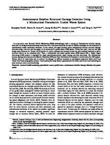
element thickness, cross sections, fibre angles, and concentrated masses. To handle strength or stifmess designs, restrictions on stresses, strains, buckling loads, natural frequencies, dynamic modes, dynamic responses, aeroelastic efficiencies, flutter speed and generalized displacements can be taken into account as constraints. Besides isotropic, orthotropic and anisotropic materials the design of composite strwtwes is of main concern. The primary aim is to minimize the structural weight subject to the selected restrictions. But sometimes the problem in question is to get a feasible design and the weight is less important. The extended range of mathematical programming codes, the modular architecture and the possibility to take all selected constraints simultaneously into consideration are the highlights of the program system. The general program architecture is shown in Fig. 1 and Ref. 9 explanes the system in more detail.
2. TECHNICAL. APPROACH The computer aided stn~twaI optimization system DASALAGRANGE (Ref 8,9) was used to perform the applications shown. This system is based on finite element methods as well as on nonlinear mathematical programming codes.
2.1 Description of Optimization Method The general formulation of structural optimization task can be stated as a nonlinear programming problem (NLP, see Ref. 7): f(x) = min
XE91fl
subject to a set of inequality constraints g,(x) 2 0 Y, < x I X”
j E3= {l,..J?z}
The objective function I(x) is general the weight or volume of the stroctore which is linear with respect to the design variables. But it is also possible to use other objective fonctions for the updating with the aim of minimum changes of the FE model:
Forthermore multiobjective problems can be handled by what is called vector optimization. The design variables can be considered as three di&rent types of stmctwal parameters: 1. sizing variables like Figure 1: General Program Architecture Design models are represented by their objective function, their design variables (parameters) and many different constraints (restrictions). Available design variables are
.
cross sectional areas for tress and beam elements.
l
wall thickness for membrane and shell elements.
l
1089
laminate thickness for all single layers in composite elements.
2 . concentrated masses to balance dynamic behaviour.
r + r r - r withF= dadb=” which is the same as 2
3 . angles of fibre directions for layered composite materials.
Ir(x)-Fl 0 g(r)=l--‘dw
g,(r)=Ar+(r(x)-i)>O
i
if
r(x) 2 F
f
r ( x )