22nd International Conference on Microelectronics (ICM 2010)
Optimization of Recursive Sorting Algorithms for Implementation in Hardware Dmitri Mihhailov
Valery Sklyarov
Iouliia Skliarova
Alexander Sudnitson
Computer Department, TUT, Tallinn, Estonia
[email protected]
DETI/IEETA, University of Aveiro, Aveiro, Portugal
[email protected]
DETI/IEETA, University of Aveiro, Aveiro, Portugal
[email protected]
Computer Department, TUT, Tallinn, Estonia
[email protected]
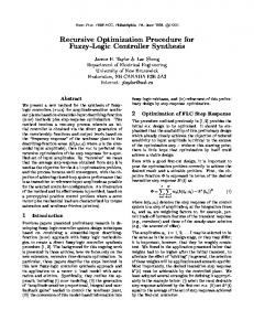
Abstract—The paper describes the hardware implementation and optimization of recursive algorithms that sort data using binary trees. Since recursive calls are not directly supported by hardware description languages, they are implemented using the known model of a hierarchical finite state machine (HFSM). The paper suggests new hardware-oriented recursive algorithms, describes their implementation in hardware; reports the results of numerous experiments; provides analysis and comparison of alternative and competitive techniques. The results clearly demonstrate that performance of sorting operations is increased comparing to other known implementations. Index Terms—Circuit synthesis, Field programmable gate arrays, Finite state machines, Sorting; Tree data structures
I. INTRODUCTION ecursion is a powerful problem-solving technique [1] that may be applied to problems that can be decomposed into smaller sub-problems that are of exactly the same form as the original. Many examples that demonstrate the advantages of recursion are presented in [1-12]. An in-depth review and comparison of different approaches to hardware implementation [3-10] appears in [13]. The advantages and disadvantages of recursive techniques in software are well known [1]. It has been shown however [5] that recursion can be implemented in hardware more efficiently than in software. Recursive algorithms are frequently used in a wide range of practical applications [1]. They are employed most often for various kinds of binary search [1, 5]. Let us consider an example of using a binary tree for sorting data [1]. Suppose that the nodes of the tree contain three fields: a pointer to the left child node, a pointer to the right child node, and a value (e.g. an integer or a pointer to a string). The nodes are maintained so that at any node, the left sub-tree only contains values that are less than the value at the node, and the right sub-tree contains only values that are greater. Such a tree can easily be built and traversed recursively. Sorting of this type will be considered in the paper as a case study to demonstrate the proposed new techniques and their advantages. A brief summary of what is new and distinctive in this paper is given below: • The analysis and comparison of alternative and competing techniques for describing hierarchical algorithms. The basis
R
978-1-61284-150-2/10/$26.00 ©2010 IEEE
471
for the comparison is the results obtained for recursive sorting algorithms in [5-7] that have already been compared in [5-7] with other known techniques. This paper suggests several improvements in the description of such algorithms and demonstrates advantages confirmed by FPGA-based implementations and experiments. • New hardware architectures based on the use of dual-port memories. • Parallel implementations. The remainder of this paper is organized in four sections. Section II is dedicated to recursive data sorting with the emphasis on the innovations proposed. Section III reports the results of experiments. Section IV presents comparisons and analysis of the models, methods and implementations in hardware and software. The conclusion is given in Section V. II.
RECURSIVE DATA SORTING
A. A Known Technique Algorithms for many computational problems are based on the generation and traversal of a binary tree where the recursive technique is very helpful. Indeed, during the search for the proper place for a new data item we can: 1) compare the new data item with the value of the root node to determine whether it should be placed in the sub-tree headed by the left node or the right node; 2) check for the presence of the node selected by 1) and if it is absent, create and insert a new node for the data item and end the process; 3) repeat 1) and 2) with the selected node as the root. Recursion can easily be applied in point 3. Let us assume that a tree for sorting has already been built. Now we would like to use the tree to output the sorted data. Fig. 1 demonstrates the known technique [5] where there are 10 incoming data items in the sequence shown (a) that are extracted from the tree in accordance with the algorithm (b). The data items are stored in RAM along with the addresses of the left (LA) and right (RA) sub-trees (c). All other details can be found in [5,6]. Let us call this known method S1. It is known [14] that recursive algorithms can be specified by hierarchical graph-schemes (HGS). A HGS can easily be converted to a hierarchical finite state machine (HFSM) and then formally described in a hardware description language (HDL) using the HDL templates proposed in [5]. The resulting
(customized) HDL code is synthesizable and permits the hardware to be designed. Two different HFSM models with explicit and implicit modules are known and all necessary details can be found in [15]. a)
b)
19 17 11
7
no
22 35
20 15
21
z
Begin Left sub-tree exists
Right sub-tree exists
yes
no
yes
Call z again for left node as a root
Call z again for right node as a root
Output data from the last node
End
Fragment of a tree
31
Sequence 1) 2) 3) 4) 5) 6) 7) 8) 9) 10) of input: 19, 22, 17, 20, 35, 11, 21, 31, 15, 7 Output: 7, 11, 15, 17, 19, 20, 21, 22, 31, 35
to be the next smallest and: a return from the recursively called module z is performed; the buffer register receives the data for b; and the value 17 from b is sent to the output as the next smallest. The module z1(µ=right) does not detect any right sub-tree from b and, thus a new return from the recursively called module is executed; and the buffer register receives data for a. Now the value 19 from a is considered to be the next smallest. After that a similar sequence of operations will be executed for the right subtree of a, i.e. for the sub-tree with the root c.
a)
z
b)
Buffer register Data LA RA
Begin Replace µ with “left” for this fragment
z1(µ µ)
µ sub-tree exists
no
yes c)
RAM Data
LA
sub-tree exists for µ node
RA
for left
Fig. 1. Binary tree for data sort (a); recursive algorithm for data sort (b); contents of memory (c)
for left
yes
no
Data LA RA Data LA RA Port A Port B Data LA RA Data LA RA
Output data from the last root
Output data from µ node
z1(µ µ)
dual-port RAM Buffer register a 19 b c RAM: Port A 19 RAM: Port B 17 d no 22 e f 22 c RAM: Port A b 17 11 g h d e 20 f 35 RAM: Port A 11 7 no no
no
µ sub-tree exists
yes
sub-tree exists for µ node
c)
B. Innovation It is shown below that the known algorithm [5] can be improved (can be made faster) in hardware through the use of dual-port memories, algorithmic modifications and simultaneous traversal of the left and right sub-trees. The main difference in the first new method (let us call it S2) is that it uses dual-port memories (described below) and a buffer register to store the currently selected node in the format: data+LA+RA. Fig. 2 gives the necessary details. The dual-port memory permits two words to be accessed simultaneously through LA and RA of the buffer register. Each word stores similar information to the buffer register (i.e. data+LA+RA) for the left and for the right nodes. There are two basic fragments in the proposed algorithm z1(µ) (see Fig. 2b) that are shown in gray at the top and bottom. Initially, the buffer register holds the root of the sorting tree. The top module z1(µ=left) examines left sub-trees. If a left sub-tree (node) exists then it is checked again, i.e. to determine whether the left subtree also has either left or right sub-trees (nodes). If there is no sub-tree from the left node, then the value of the node is the leftmost data value and can be output as the smallest. In the last case the node in the buffer register holds the second smallest value and the relevant data value is sent to the output. The bottom module z1(µ=right) performs similar operations for right nodes. Let us consider the example in Fig. 2c, where addresses are designated by letters a,b,…,j. Initially, the buffer register contains the data for the root node. There is a left node b from a and a left node from b. Thus, z is called again recursively and the buffer register stores the data for b. Then z is called recursively once again and the buffer register stores the data for d. There is a left node g from d but there are no child nodes from g (neither left nor right). Thus, the value 7 of g is chosen as the smallest, the value 11 from d is selected as the second smallest and z1(µ=right) at the bottom is started. There is the right node h from d but there are no child nodes from h. Thus, the value 15 of h is considered
472
g
7
h 15
i
21
Call z again for µ node as a root
yes Call z again for µ node as a root
no End Replace µ with “right” for this fragment
Output data from µ node
31 j
Fig. 2. The first improvement (S2): the use of dual-port memory (a); algorithm (b); example (c)
If you look at Fig. 2b you can see that the module z1(µ) at the top is exactly the same as the module z1(µ) at the bottom. Indeed, just the argument µ is different: in the first case µ=left and in the second case µ=right. Thus, we can benefit again from the hierarchy supported by a HFSM model and use the same module z1(µ) (and, consequently, the same circuit) with different input data that can be properly chosen by a multiplexer. The main difference in the second new method (let us call it S3) is the checking of LA and RA for each word in the dual-port RAM independently. The top-level algorithms is the same as in Fig. 2b (see Fig. 3a), but the module z1(µ) is different (see Fig. 3b). Let us consider the same example shown in Fig. 2c. Suppose, the left sub-tree of the tree in Fig. 2c has already been traversed and we got the sorted sequence: 7, 11, 15, 17, 19. The last value (19) is taken in the middle rectangle of Fig. 3a. So, z1(µ=right) has to be called next. Since a right sub-tree (beginning with the node c) of the node a exists and it (i.e. c) has the left node e, the module z will be called again for the node c. The module z1(µ=left) detects the left node e, which does not have any left node. Thus, the value 20 is selected. Since the node e has the right node i, the module z is called again for the node i. Note that the module z is not called for the node e and the control jumps directly from the node c to the node i. This is the main difference with S2. The node i does not have a left sub-tree (which is why
the value 21 is chosen), or a right sub-tree (which is why the return from the recursive module is performed). The node c becomes the current active node and the value 22 is selected. Then the module z1(µ=right) is executed. The node c has the right node f and f has the left node j. Thus, the value 31 is selected. The node f does not have a right sub-tree and the value 35 is the last value in the sorting sequence. After that there is one more return from the recursive module and the algorithm is terminated. a) z
Begin
b)
Begin
z1(µ)
µ sub-tree exists
z1(µ=left)
no
yes Output data from the last node
no
left sub-tree exists for µ node
yes z1(µ=right)
Call z again for µ node as a root
Output data from µ node
End yes
right sub-tree exists for µ node
no
Four algorithms described in section II: S1 (the known algorithm) and S2, S3, and S4 (the three algorithms proposed in this paper). For all algorithms S1,…,S4 the HFSM with explicit modules [15] was used. The results are presented in Table I. The columns SN (N∈{1,2,3,4}) indicate the number of clock cycles for sorting by the algorithm SN; the Data column indicates the number of data items that were sorted; the l/r column indicates Number of nodes of left sub-tree from the root/Number of nodes of right sub-tree from the root. 2. For two algorithms described in section II S1 and S3 the HFSM with implicit modules [15] was used. Let us call the relevant implementations S1n and S3n. The number of clock cycles is the same as for the columns S1 and S3 in Table I. Besides, the algorithm S1 was described in C++ and implemented in software. Other algorithms (S2, S3, S4) are hardware-oriented and their advantages have appeared just in hardware. The same data (randomly generated) were used for the software implementations. The results were produced on HP EliteBook 2730p (Intel Core 2 Duo CPU, 1.87 GHz) computer.
End
TABLE I.
Call z again for right node as a root
Fig. 3. The second algorithm: top-level module z (a); module z1(µ) (b)
In the last method that we propose (let us call it S4), the left (such as the sub-tree with the root b in Fig. 3c) and right (such as the sub-tree with the root c in Fig. 3c) sub-trees of the tree are traversed in parallel using the method S1. There are two simultaneously functioning HFSMs that are a master and a slave. The master HFSM builds the tree, outputs the left sub-tree, and activates the slave HFSM when necessary. The slave HFSM outputs the right sub-tree. Processing of both sub-trees can be done simultaneously. The main objective of the method S4 is to evaluate the potential benefits of parallelism. Obviously, more parallel branches can be introduced using cascade structures. III.
1.
FPGA-BASED IMPLEMENTATIONS AND EXPERIMENTS
A. Experiments The synthesis and implementation of the circuits from the specification in VHDL were done in Xilinx ISE 11 for FPGA Spartan3E-1200E-FG320 of Xilinx. A random-number generator produces 211 items of data with a length of 14 bits (i.e. values in an interval between 0 and 16383). Values greater than 9999 are removed leaving 1200-1300 items available for further processing. These items are sorted using the following FPGAbased implementations:
473
Data 1286 1278 1248 1211 1216 1248 1203 1228 1212 1230 1305 1259 1230 1304 1276 1225 1225 1199 1309 1204
IV.
l/r 1/1284 53/1224 143/1104 185/1025 266/949 322/915 460/742 528/699 556/655 623/606 742/562 822/436 799/430 849/454 963/312 958/256 986/238 1051/147 1288/20 1203/0
THE RESULTS OF EXPERIMENTS
S1 5143 5111 4991 4843 4863 4991 4811 4911 4847 4919 5919 5035 4919 5215 5103 4899 4899 4795 5235 4815
S2 3841 3854 3779 3637 3687 3743 3608 3705 3639 3722 3896 3796 3665 3925 3813 3699 3705 3586 3927 3603
S3 3589 3584 3467 3373 3393 3486 3350 3432 3350 3470 3596 3496 3419 3610 3564 3417 3420 3319 3639 3387
S4 6424 6124 5524 5129 4749 4579 3714 3499 3279 3101 3533 3727 3629 3853 4167 4101 4185 4354 5175 4816
ANALYSIS OF THE RESULTS AND COMPARISONS
A. Performance The algorithm S3 gives the best results as a rule (see Table I). Nevertheless, the results of S4 are better for well balanced trees. We believe that additional research efforts are needed to explore the potential for parallel sorting and the results look promising. The experiments have shown that the hardware implementations are faster in about 4.5 times than software implementations for all the experiments even though the clock frequencies of the FPGA and the PC differ significantly.
B. Resource Consumption Fig. 4 shows the resource (Slices, CLBs, BRAMs) consumption and maximum clock frequency for different implementations, where: • b indicates that the stacks for HFSMs are built from Block RAM. For all implementations not marked with b the stacks are built from LUTs; • n designates the HFSM with implicit modules; • codec indicates that decoding (to minimize the size of the stack) has been used (see [15] for details); • m denotes an additional level of modularity, as in Fig. 3. As can be seen, the circuits in which the stacks are built from block RAMs consume the least number of slices and CLBs and they require 1 or 2 additional block RAMs. However, the maximum clock frequency for such circuits is lower than for similar implementations with the stacks built from CLBs.
demonstrates the advantages of the innovations proposed based on FPGA prototyping and abundant experiments. Recommendations and discussions are also presented. Obviously, the results of the paper are not limited to just recursive sorting. They have a wide scope and can be applied effectively to systems that implement algorithms over tree-like structures. ACKNOWLEDGMENT This research was supported by the European Union through the European Regional Development Fund and by the Estonian Doctoral School in Information and Communication Technology. REFERENCES [1]
Number
[2] [3]
[4]
Implementations Frequency in MHz Number of BRAMx10
[5]
[6]
[7]
[8]
Implementations [9] Fig. 4. Resources needed and maximum clock frequency for different implementations
Note that the chosen FPGA is very cheap and not very fast. The use of significantly more advanced and faster FPGAs available on the market (e.g. Virtex-5/6 families) would permit even faster recursive sorting circuits to be implemented. An analysis of Table I and Fig. 4 permits the following conclusions to be drawn: 1) the algorithm S3 provides, as a rule, the best performance; 2) the implementation S1nb_codec requires the smallest hardware resources; 3) the implementations S2m and S3m better support modularity and reusability and offer potential for refinement; 4) we found that the developed hardware is easily scalable and can be used for any number of data items bounded just by FPGA resources. V.
CONCLUSION
The paper suggests new hardware-oriented algorithms for solving sorting problems over tree-based structures, and clearly
474
[10] [11]
[12]
[13]
[14]
[15]
T.H. Cormen, C.E. Leiserson, R.L. Rivest, C. Stain, Introduction to Algorithms, 2nd edition, MIT Press, 2002. J.V. Nobble, “Recurses!”, Computing in Science & Engineering, May/June 2003, vol. 5, issue 3, pp. 76-81. T. Maruyama, M. Takagi, T. Hoshino, “Hardware implementation techniques for recursive calls and loops”, Proc. 9th Int. Workshop FPL’99, Glasgow, UK, 1999, pp. 450-455. T. Maruyama, T. Hoshino, “A C to HDL compiler for pipeline processing on FPGAs”, Proc. IEEE Symp. on Field-Programmable Custom Comp. Machines - FCCM’2000, CA, USA, 2000, pp. 101-110. V. Sklyarov, “FPGA-based implementation of recursive algorithms,” Microprocessors and Microsystems. Special Issue on FPGAs: Applications and Designs, vol. 28/5-6, pp. 197–211, 2004. V. Sklyarov, I. Skliarova, B. Pimentel, "FPGA-based Implementation and Comparison of Recursive and Iterative Algorithms", Proc. 15th Int. FPL'2005, Finland, 2005, pp. 235-240. I. Skliarova, V. Sklyarov, "Recursive versus Iterative Algorithms for Solving Combinatorial Search Problems in Hardware", Proc. 21st Int. Conference on VLSI Design, Hyderabad, India, 2008, pp. 255-260. G. Ferizis, H. ElGindy, “Mapping recursive functions to reconfigurable hardware”, Proc. 16th Int. Conference FPL’06, Madrid, Spain, 2006, pp. 283-288. S. Ninos, A. Dollas, “Modeling recursion data structures for FPGA-based implementation”, Proc.18th Int. Conference FPL’08, Heidelberg, Germany, 2008, pp. 11-16. G. Stitt, J. Villarreal, “Recursion flattering”, Proc. 18th ACM Great Lakes symp. on VLSI – GLSVLSI’08, FL, USA, 2008, pp. 131-134. S.A. Edwards, “The Challenges of Synthesizing Hardware from C-Like Languages”, IEEE Design & Test of Computers, vol. 23, issue 5, September-October 2006, pp. 375-386. R. Rugina, M. Rinard, ”Recursion unrolling for divide and conquer programs”, Proc. 13th Int. Workshop on Languages and Compilers for Parallel Computing - LCPC’2000, NY, USA, 2000, pp. 34-48. I. Skliarova, V. Sklyarov, "Recursion in Reconfigurable Computing: a Survey of Implementation Approaches", Proc. 19th Int. Conference FPL’2009, Prague, Czech Republic, 2009, pp. 224-229. V. Sklyarov, “Hierarchical Finite-State Machines and their Use for Digital Control”, IEEE Transactions on VLSI Systems, 1999, vol. 7, no. 2, pp. 222-228. I. Skliarova, V. Sklyarov, “Reconfiguration Technique for Adaptive Embedded Systems”, Proc. of ICIAS’2010, Kuala Lumpur, 15-17 June, 2010.