Optimization of vehicle licence plate segmentation and symbol recognition R.P. van Heerden and E.C. Botha Department of Electrical, Electronic and Computer engineering University of Pretoria, South Africa
[email protected],
[email protected]
Abstract We address the problem of optimising the recognition of vehicle licence plates with multiple segmentation methods. Two different licence plate search algorithms and seven symbol segmentation techniques are compared. The two search algorithms are: a region-growing algorithm (RGA) and an algorithm based on vertical edge detection (VEDA). The two search algorithms identify a licence plate region in the image, from which the symbol segmentation techniques extract the licence plate symbols. Once the region in which the licence plate is located is identified, seven algorithms are used to segment the licence plate symbols. These algorithms comprise different combinations of simple segmentation, thresholding on the vertical projection, single and double frame Viterbi searches and filtering the data. Once the symbols have been identified, a multilayer perceptron neural network is used to estimate symbol probabilities of all the possible symbols. Legal licence plate sequences are used to construct a Markov model containing all allowed symbol orderings. By adapting the Viterbi algorithm with sequencing constraints, the most likely licence plate symbol sequences are calculated, along with a measure of their likelihoods. Each technique generates a recognition confidence score, which allows for combining and weighing the different methods to achieve the best segmentation results. Our results presented in this paper show that by combining the pre-segmentation techniques, the average score and the recognition rate improves.
1. Introduction The problem of licence plate recognition can be solved by a multitude of recognition methods. Each different method also has a multitude of parameters. These parameters need to be optimised. Our approach do not optimise parameters, but rather use a wide spectrum of values and a confidence score, in order to use the whole spectrum. In this paper, we describe and evaluate two licence plate location detection algorithms, as well as several licence plate symbol segmentation algorithms. We then investigate how to combine these algorithms and their parameters to optimize symbol recognition. The organisation of this paper is as follows. In Section 2 we describe the two licence plate position identification techniques, Section 3 discusses the symbol segmentation, Section 4 the symbol recognition (probability estimation), Section 5 the experimental results and Section 6 concludes the paper.
2. Licence plate position identification techniques The two search algorithms were tested: a region-growing algorithm (RGA) and an algorithm based on vertical edge detection
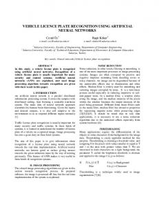
(VEDA). 2.1. Region growing algorithm The position of a licence plate can be estimated by identifying possible licence plate symbols [1] and then looking for symbols that conform to the following specifications: • the background of the symbol is lighter than the symbol, • the symbol’s width to height ratio is within tight specifications, • the symbols are oriented in a straight line. To identify the symbols, the grey scaled image is reduced to a binary image by thresholding each pixel [2]. The influence of different lighting conditions can be reduced by adaptively computing the threshold [3]. By using a recursive region-growing algorithm, the dark regions (licence plate symbols) surrounded by light areas (background of the licence plate) can then be classified. Each region has a unique position and dimensions. 2.2. Vertical edge detection algorithm A new algorithm based on the fact that a licence plate contains a significant number of vertical edges (VEDA) [4], was also tested. The vertical edges of a licence plate are characterised by large differences in grey-level of adjacent pixels. The new algorithm works as follows: • take a horizontal cross-section through the image at every nth line of the image, where n must be less than the height of the smallest character expected, • for each pixel in the current cross-section, if the difference in grey-level between the pixel and its neighbourhood is greater than some threshold T , the pixel is marked as a vertical edge, • cluster all vertical edge points into groups so that the horizontal distance between vertical edge points in the same cluster is less than the width of the largest character expected, • merge clusters which are vertically adjacent into a single cluster. An example of a number of clusters is shown in Figure 1, with the possible licence plate locations indicated with lines of clusters. Executing this algorithm yields a number of clusters, where each line of clusters represents left and right extrema of a possible licence plate. The bottom and top edges of the licence plate are found as follows:
Figure 1: Possible licence plate locations. • take the horizontal line between the left and right extremes of the possible licence plate and divide it into a number of intervals, • for each interval find the estimate for the position of the top and bottom of the plate as follows: – place a 1-pixel thick horizontal bar over the current interval of the horizontal line and count how many vertical edges there are in the image through the bar, – slide the bar upwards, one pixel at a time and count the number of edges through the bar, – when the bar passes over the number plate symbol, the number of edges will be zero, – the bar is slid no further than the largest character expected, – repeat for the bottom part of the licence plate symbols. In Figures 2 and 3 the possible licence plate locations are shown with black lines, while the top and bottom edges of the licence plates are shown with grey lines. The grey lines indicate where the licence plate symbols end. Only on the real licence plate will these end points form two lines as shown in Figure 3.
Figure 3: The licence plate borders of Figure 2 .
The left and right borders detected by the above method will normally be too wide. The edge between the licence plate and the rest of the car normally forms the left and right border as seen in Figure 3. This algorithm thus produces the region where the licence plate symbols are located. We used the RGA to extract the licence plate symbols from the licence plate region, as identified by the VEDA.
3. Symbol segmentation For good quality images, the symbol segmentation can be achieved by only using a region growing algorithm [1, 5]. Each region is identified as a unique symbol. Two kinds of errors frequently occur: More than one symbol is grouped as one or one symbol is split into more than one region. These errors occur when the licence plate is dark or too brightly illuminated. By adapting a threshold offset [5], dark and lightly lit licence plates symbols can be separated. 3.1. Vertical projection separation of symbols
Figure 2: The location of possible licence plate borders. Clusters which represent licence plates can be identified as follows (and all the other clusters thus removed): • more than half of the top symbols borders are in a row, • more than half of the bottom symbols borders are in a row, • the angles of the top and bottom row are the same and within certain limits, • the vertical height of the symbol (distance between top and bottom border) is within certain limits.
Some of the new licence plate symbols (Mpumalanga , North West, Eastern Cape and Northern Cape Provinces) can not be separated only with region growing and variable threshold offsets, as the licence plate contain dark background figures which will result in multiple symbols segmented as single entities (merging). Physical objects clinging to the plate or damage can also result in symbol merging . Examples of licence plate symbols which can not be separated are shown in Figure 4. All of the symbol overflow in Figure 4 occur in the horizontal spaces between the symbols. Overflow between licence plate symbols and regions above and below the licence plate is rare, and can mostly be solved with variable threshold offsets. The overflow structure is usually only a few pixels high, and smaller than the height of the symbols. If the overflow height is small, the symbols can be separated by using the vertical projection of the licence plate. Figure 5 shows the vertical projection of the licence plate images of Figure 4.
Original Image
Vertical projection
Symbol borders
Filtered Vertical projection
Symbol borders Figure 4: Example of licence plate images which can not be separated with binarisation and region growing. Figure 6: An example of symbol separation with vertical projection.
Figure 5: Vertical projections of licence plate images of Figure 4.
The licence plate symbols can be separated from each other by using the following characteristics of the vertical projection: • each symbol lies above a threshold on the vertical projection , • each symbol lies between two major valleys of the projection, • each symbol lies between a positive and a negative derivative of the vertical projection. Noise on the licence plate symbols can lead to false symbol borders. The noise is inherent in the picture or is generated from the binarisation step. By using a simple digital low-pass filter the noise in the vertical projection was reduced. In Figure 6 an example of symbol separation applying the above rules on the vertical projection is shown. The white ver-
tical lines show the start position of each symbol and the black vertical lines show the end positions. With or without the filter it may not always be possible to separate all the symbols without splitting some of the symbols. Extremely thin symbols are sometimes removed as noise. Some licence plate symbols can never be separated because the overflowing/merged structures are thicker than one or more of the other characters. In Figure 4 the BLW 123M P licence plate is such an example. The M and W symbols will always be split into two symbols each before the 1 and 2 symbols are separated. By over-segmenting [6] [7], and combining, licence plate symbols (as seen in Figure 4) can be successfully segmented. For the majority of the over-segmentation cases it can be assumed that a symbol is split into one or two segments. Extremely thin frames are removed and assumed to have originated from noise. It is assumed that each symbol is directly followed by the next symbol. The province logo of Gauteng licence plates is removed by only selecting the symbols with a vertical projection above a certain threshold. Over-segmented images are used with the constrained Viterbi symbol alignment algorithm described by van Heerden et al. [8].
4. Symbol probability estimation 4.1. Neural network A multilayer perceptron neural network was used for classification of the segmented symbols. It was trained with features computed by fitting a scaled mesh function on the input symbols [9, 1]. The features chosen were 82 regions of the symbol, each of which was represented by a value between 0 and 1. The percentage of ‘on’ (black) pixels in each block determined the value. If a block was completely white then the value of that block would be 0, and the value would be 1 if a block was to-
α
α
η
η
η
Optimisation of local threshold offset value T
G
P End State
Start State
E
C
α
η
η
η
C
η
Figure 7: Partial Markov model of licence plate templates.
Number of Images with segmentation errors
α
75
70
65
60
55 −15
−10
−5
0
5
Offset value
Figure 9: Optimisation of local threshold offset value.
Figure 8: Example of a licence plate in which all symbols can not be separated without splitting some of the symbols.
tally black. These features were then classified using a feed-forward neural network [10, 11]. The neural network weights were trained using input images rotated in and out-of-plane to simulate the effect of a full range of different view angles. The feed-forward neural network had 34 outputs (0-9 and A-Z excluding O and I). Each symbol generated an output vector with 34 elements. Each neural network output value maps to a single class of character. The output nodes of the neural network restricted the possible outputs within the range (0 and 1) as determined by the sigmoidal transfer function. These output values approximate the class membership probabilities of the symbols. 4.2. Hidden Markov modeling Hidden Markov modeling has been used previously with great success in speech recognition [12]. We apply some of the same concepts to licence plate recognition [13]. The Markov model used is a left to right model. Each state in the Markov model represents a licence plate symbol. Legal licence plate templates formed the paths through the Markov Model. In Figure 7 the model for the old Transvaal, Gauteng, Eastern Cape and old Cape provincial numbering schemes is shown. In Figure 7, α represents characters A tot Z, η represents 0 to 9 and each element of the set (C, T, G, E and P) represents the characters C, T, G, E, and P respectively. In Figure 8 a licence plate in which the symbols can not be separated is shown. The possible symbol boundaries are also shown. Each symbol is only one or two divisions wide. If all the possible symbols (one and two divisions away from each starting point) in Figure 8 are considered, several false regions will be present. The templates of legal licence plates and the
symbol probabilities are now used in a hidden Markov model to calculate the most likely licence plate symbol sequence. This is implemented by first calculating all the symbol probabilities and then applying an adapted Viterbi search algorithm [14, 8] to find the most likely solution. When more than one division (as seen in Figure 8) may form a symbol, we use the term “double frame Viterbi”. The output of the Viterbi search algorithm is used as a confidence score.
5. Experiments and results The experiments were performed off-line on the images captured with standard commercial video and security cameras. The video camera stored the images to tape, which was digitised using a Matrox Meteor card. The data set included slow-moving and stationary vehicles. The digitised images were processed on an Intel-based PC running Linux. All testing was done on 318 images. 5.1. Comparison of licence plate location techniques With the RGA technique, the value of the offset of the threshold had a large influence on the system results. As seen in Figure 9, the number of segmentation errors for a zero offset is much higher than the rest. With a zero offset a high level of noise is introduced, which increases the segmentation errors. An iterative approach which used all the different threshold offset values and the score generated by the Viterbi search algorithm, achieved a much higher success rate than any specific offset value (see Table 1). For each threshold offset value, a possible licence plate sequence and score was generated. The sequence with the best score was kept. Threshold offset -8 (Best threshold offset) Combination all threshold offsets
Segmentation Errors 57 22
Table 1: The advantage of an iterative thresholding approach The VEDA technique was not as successful as the RGA technique. Out of the 318 images, 120 segmentation errors
occurred compared to the 22 segmentation errors of RGA. By combining the two search algorithms, the number of segmentation errors was reduced to 19. The comparison between licence plate segmentation techniques is shown in Table 2. Licence plate segmentation Technique Region growing Vertical edges Combination of both techniques
Percentage segmentation errors 6.91 % 37.8 % 5.97%
Thus the highest recognition rate was achieved by a combination of techniques excluding the double frame Viterbi methods. Thus the highest average confidence score did not map to the highest segmentation rate. Figure 10to 12 show confidence score distributions of the symbol segmentation techniques of Table 4. 0.25
Recognised Failed to recognise 0.2
Table 2: Comparison of licence plate segmentation techniques
5.2. Comparison of the symbol segmentation techniques
Data set
0.15
0.1
The symbol classification / recognition rates (classification by the neural network) for the different segmentation techniques, are shown in Table 3. % Correctly classified 82.70 % 70.56 %
0 −0.2
0
0.2
0.4
0.6
0.8
1
1.2
Scores
Figure 10: Confidence score distributions of simple segmentation.
71.01 % 0.1
74.21 %
Recognised Failed to recognise
0.09
0.08
28.80 0%
1.26%
Table 3: Comparison of symbol classification rates for different segmentation techniques
0.07
0.06
Data set
Segmentation technique Simple segmentation Vertical projection with single frame Viterbi Vertical projection with filtered data and single frame Viterbi Vertical projection with double frame Viterbi Symbols between valleys with filtered data and double frame Viterbi Symbols between valleys and single frame Viterbi Symbols between valleys with filtered data and single frame Viterbi
0.05
0.05
0.04
0.03
0.02
0.01
The segmentation errors were reduced when the different techniques were combined, each technique generating a possible licence plate and score (see Table 4). The sequence with the best score was kept. Segmentation technique Simple segmentation Combination of all techniques Combination of all techniques except the double Viterbi techniques
% Correctly classified 82.70 % 83.65 %
86.48 %
Table 4: Comparison of symbol classification rates combining segmentation techniques. By combining the pre-segmentation techniques, the average recognition rate was improved. The techniques which used double frame Viterbi unfortunately failed to recognise some licence plates while still giving its attempt a high confidence score.
0 −0.2
0
0.2
0.4
0.6
0.8
1
1.2
Scores
Figure 11: Confidence score distributions of combination of all techniques. In comparison, the average score of the errors (failed to recognise) in Figure 12 was much higher than in Figure 11, although the technique of Figure 12 achieved better segmentation results.
6. Conclusion For the licence plate recognition problem, the number of segmentation errors is dramatically reduced by using a combination of different threshold values. More than one segmentation method was combined in cases where a credible confidence score exists. We combined two different licence plate segmentation techniques by comparing the confidence scores and keeping the best
0.09
[8] R. van Heerden, C. Nieuwoudt, and E. Botha, “Recognising non segmentable vehicle licence plate symbols,” in Proceedings of the Ninth Annual South African Workshop on Pattern Recognition, (Stellenbosch University, Stellenbosch), pp. 35–38, Nov. 1998.
Recognised Failed to recognise
0.08
0.07
Data set
0.06
[9] S. W. Lee, “Off-line recognition of totally unconstrained handwritten numerals using multilayer cluster neural networks,” IEEE Transactions on Pattern Analysis and Machine Intelligence, vol. 18, pp. 649–650, June 1996.
0.05
0.04
[10] G. L. Martin and J. A. Pittman, “Recognizing handprinted letters and digits using backpropation learning,” Neural Computation, no. 3, pp. 259–267, 1991.
0.03
0.02
0.01
0 −0.2
0
0.2
0.4
0.6
0.8
1
1.2
Scores
Figure 12: Confidence score distributions of combination of all techniques except the double frame Viterbi techniques. result of the Viterbi search in a hidden Markov model framework. When the confidence score was not credible (such as the case with our “double frame Viterbi”, the combined recognition rate decreased. In conclusion, we achieved a 93.7% (complete) correct licence plate recognition rate on a test set of 318 images with the segmentation and recognition algorithms described in this paper. An online version of our system can be viewed at http://eerc.up.ac.za/˜renier/M
7. References [1] C. Nieuwoudt and R. van Heerden, “Automatic number plate segmentation and recognition,” in Seventh annual South African workshop on Pattern Recognition, (University of Cape Town), pp. 88–93, IAPR, Nov 1996. [2] W. Pratt, Digital Image Processing. Mountain View, California: Sun Microsystems, Inc, 1991. [3] X. Liu and R. W. Ehrich, “Subpixel edge location in binary images using dithering,” IEEE Transactions on Pattern Analysis and Machine Intelligence, vol. 17, p. 631, June 1995. [4] C. Setchell, Applications of Computer Vision to Roadtraffic Monitoring. PhD thesis, Department of Computer Science, University of Bristol, September 1997. [5] Y. K. Siah, T. Y. Haur, M. Khalid, and T. Ahmad, “Vehicle licence plate recognition by fuzzy Art-map neural network,” (Faculty of Electronic Engineering, University Teknologi Malaysia, Jalan Semarak, Kuala Lumpur), Centre for Artificial Intelligence and Robotics. [6] M. Koga, T. Kagehiro, H. Sako, and H. Fujisawa, “Segmentation of Japanese handwritten characters using peripheral feature analysis,” in International Conference on Pattern Recognition, (Brisbane, Australia), pp. 1137– 1141, ICPR, August 1998. [7] J. Mao, P. Sinha, and K. Mohiuddin, “A system for cursive handwritten address recognition,” in International Conference on Pattern Recognition, (Brisbane, Australia), pp. 1285–1287, ICPR, August 1998.
[11] S. Knerr, L. Personnaz, and G. Dryfus, “Handwritten digit recognition by neural networks with single-layer training,” IEEE Transactions on Neural Networks, vol. 3, pp. 962–968, November 1992. [12] L. R. Rabiner and B. H. Juang, “An introduction to hidden Markov models,” IEEE ASSP Magazine, pp. 4–7, January 1988. [13] R. van Heerden and C. Nieuwoudt, “A connectionist approach to vehicle licence plate recognition,” in Eighth annual South African workshop on Pattern Recognition, (Rhodes University), pp. 75–79, IAPR, Nov 1997. [14] H. F. Siverman and D. P. Morgan, “The application of dynamic programming to connected speech recognition,” IEEE ASSP Magazine, pp. 30–32, July 1990.