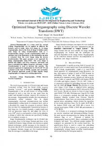
SETIT 2009
5th International Conference: Sciences of Electronic, Technologies of Information and Telecommunications March 22-26, 2009 – TUNISIA
Optimized CCII-Based Tuneable Filter and Oscillator using Minimum Number of Passive Elements Mourad FAKHFAKH*, Esteban TLELO-CUAUTLE**, David MORO** and Mourad LOULOU* * University of Sfax, TUNISIA
[email protected] [email protected]
** INAOE, MEXICO
[email protected] [email protected] Abstract: Two applications based on the use of second generation current conveyors (CCIIs) are presented in this paper: a voltage mode filter and an oscillator. Each application consists of two CCIIs and the minimum number of passive elements: two grounded capacitors. Both applications enjoy tunability, i.e. bandwidth of the filter and frequency oscillation of the oscillator. Tunability is performed thanks to the characteristic adjustability of the CCII. The used CCII was optimized to improve performances of the applications. SPICE simulations are illustrated to verify the theory. Key words: Multi-objective optimization, Pareto front, Tunable current conveyor, Current mode filter, Oscillator.
these applications are tunable. It is to be high lighted that both applications only comprise two CCII and two grounded capacitors, which make them desirable for VLSI realization. Since performances of such applications mainly depend on those of the CC, both the choice of the CCII topology and its performances were optimized.
INTRODUCTION Current conveyors (CC) [SMI 68], and particularly second generation CCs (CCIIs) [SED 70], have attracted the attention of researchers in the field of designing active filters and oscillators owing to their advantages. Indeed, when compared to operational amplifiers, CC offer larger bandwidth, better linearity, lower power consumption … [PAN 05], [TOU 93]. Several CC based schemes realizing active filters and oscillators have been proposed in the literature (see for instance [SOL 98] and [SOL 99]). As Soliman states in [SOL 98] most of these CCII ‘applications’ are generated from the conventional operational amplifier (op-amp) ‘ones’ using the adjoin network theorem [ROB 99], or using the transformation theorem relating a class of op-amp to CCII circuits [SOL 95], or using the nullor equivalent circuit approach [GRI 95]. These CC based applications have been extended to the domain of electronically adjustable functions. This adjustability is attributed to the current conveyor which parasitic X-port resistance value depends on the CC bias current.
The paper is structured as follows: in section 1, we present the optimized CCII. In sections 2 and 3, we present the optimized CCII and lies of the filter and the oscillator. We also present simulation results of both applications. Finally, concluding remarks are given in section 4.
1. Description and Optimization of the CCII A CCII is a three port circuit. Its relationship of the current and voltage terminals can be characterized by the matrix equation (1), where β and α represent the voltage gain from the terminals Y to X and the current gain from the terminals X and Z. Ideally, β = 1 and α = 1 . However, due to the parasitic input impedances of the CCII, its real behavior differs from the ideal one. The equivalent model for a CCII is reported in figure 1 [FER 02]. It highlights the unavoidable differences between theoretical and real
In this paper we present second-generationcurrent-conveyors-based applications employing a minimum number of passive elements, namely a band pass voltage mode filter and an oscillator. Further
-1-
SETIT2009 Indeed, RX has to present a wide variation range to allow covering a wide range of the filter’s bandwidth and the oscillator’s oscillation frequency. RX symbolic expression is given by (3),
circuit behavior. Actually, the equivalent impedances reported at each node affect performances of the CCII [FON 05], [RAJ 07].
⎡ 1 I ⎡ Y ⎤ ⎢Z ⎢V ⎥ = ⎢ βY ⎢ X⎥ ⎢ ⎢⎣ I Z ⎥⎦ ⎢ 0 ⎢ ⎣
⎤ 0 ⎥ V ⎡ Y⎤ ⎥⎢ ⎥ 0 ⎥ ⎢I X ⎥ 1 ⎥ ⎢V ⎥ ⎣ Z⎦ Z Y ⎥⎦
0 ZX
α
Lx
(1)
ZX
Cx X IX IY
ideal
Xi
Rx
CCII
IZ
Cy
Rz
Cz
Ry ZY
ZZ
real CCII
(2)
(3)
In order to satisfy both RX and RZ specifications, we elaborated a C++ program that computed all feasible solutions in the hyper space (RX vs. RZ). Then we applied a dominance criterion to generate the Pareto front, i.e. all non dominated solutions [DRE 06], [KNO 99]. Figures 3 and 4 illustrate ‘all’ feasible solutions and the Pareto front respectively.
Z
Zi
Yi
Y
1 g DSN + g DSP ( g DSP + g mP + g DSN ) RX = . ( g DSN + g mN )( g DSP + g mP ) ( g DSP + g DSN + g mN ) (2 g DSP + 2 g DSN + g mN + g mP ) RZ =
Figure 1. Equivalent model of a CCII. 1000
As it is well known that in order to minimize effects of these non-idealities, equivalent impedances ZY and ZZ have to be maximized, conversely ZX has to be minimized (Notice that LX and Cx effects will be neglected at the working frequency ranges of the treated applications). For the applications that we present, the CCII has to satisfy the following specifications:
900 800
RX
700 600 500 400 300 0.5
VDD
1
1.5
2
2.5
3
3.5
RZ M12
M10
M6
M8a
M8b
M8
4 5
x 10
M8c
Figure 3. Feasible solutions (RX vs. RZ).
M1
Y
X
Z+
1000
Z-
M4
950
M3
Ibias
M2
900 M7
M11
M9
M5
850 M7a
M7b
M7c
RX
M13 VSS
800 750
Figure 2. High Y-input impedance CCII.
700 650
• High input impedance at port Y: This is insured by a judicious choice of the CC’s lie. Thus, among CCII topologies proposed in the literature we chose the CCII depicted at figure 2. This CCII enjoys intrinsic high Y port impedance, since Y port is directly connected to the gate of a MOS transistor,
600 2
2.2
2.4
2.6
2.8
3
3.2
3.4
RZ
3.6 5 x 10
Figure 4. Non dominated solutions. The C++ program consists of the following steps:
• High input impedance at port Z, Expression ZZ is given by (2), where gDSN and gDSP refer to the drain conductances of NMOS and PMOS transistors respectively (we neglect the effect of CZ and for simplicity, we assume that NMOS transistors have the same sizes, ditto for PMOS transistors),
• First, a parameter vector is randomly generated, • Second, constraints, such as transistor saturation conditions, are checked [KNO 99], [FAK 07], à If constraints are not satisfied, a new parameter vector is generated, à If they are, RX and RZ values are computed and memorized,
• A wide range of variation of X-port resistance RX,
-2-
SETIT2009 • Once the stopping criterion is satisfied, a dominance routine is applied to all memorized parameters,
Vout C2 R2 s = Vin 1 + R2C1s + R1R2C1C2 s ²
(4)
Taking into account non idealities of both CCIIs, the transfer function will be modified as given by (5). Using the ‘optimized’ CCII proposed in paragraph II, effects of RY1 and RY2 will be neglected. As mentioned above, R1 and R2 will be removed. RX1, RX2, RZ1 and RZ2 will be taken into account. Values of X-ports’ resistances will be tuneable thanks to their dependency to the respective CCII bias current. Finally, the filter can be modified as presented in figure 6.
• Non dominated solutions are memorized in an external archive. Figure 4 gives a clear idea about possible maximal values of RZ and the variation range of RX. Thus, in the corresponding parameter space, we can choose parameters’ values, i.e. sizes of the CCII’s transistors, giving the solution corresponding to the ‘middle’ of the Pareto front. This choice allows a maximum sweep of RX values. The Pareto surface comprises 28 non dominated solutions. Table I gives parameters (in µm) corresponding to three particular points: those corresponding to edges of the Pareto front and the one located in the middle of this front. LN, WN, LP and WP denote channel length and width of a NMOS and a PMOS transistor respectively.
Ibias1 X
non ideal
CCIIVin
Y
Ibias2 Y
non ideal
CCII+ X
TABLE 1. SIZES CORRESPONDING TO THE THREE PARTICULAR SOLUTIONS First edge of the Pareto front Second edge of the Pareto front The ‘Middle’ solution
LN
WP
LP
3.85
0.35
29.90
1.00
29.20
2.65
29.85
1.05
13.30
1.25
29.75
1.00
Vout
(5)
where:
A = (1 + RZ 2C2 s ) RZ 1RX 2α1β1 . B = RZ 1RZ 2 ( RX 2C1 + RX 1RX 2C1C2 ) . C = ( RX 1C2 RZ 2 + RX 1C1RZ 1 ) . D = ( RZ 2 + RX 1 ) RX 2 + RZ 1RZ 2α1β1β 2 .
Simulation results The filter presented in figure 6 was designed using the CCIIs of figure 2 and was simulated using SPICE software. Simulation conditions are given by table II. At figure 7 we present simulation results obtained when for 10µA and 250µA bias current of CCII1. In table III we give bandwidth obtained by sweeping the Ibias range.
where I X = − I Z . It presents the advantage of using two grounded capacitors and two resistors directly connected in series to the X-ports of the CCIIs. The ideal transfer function of the filter is given by (4). Notice that to obtain a CCII- from a CCII+, the branch composed of transistors M7 and M8 of figure 2, will be replaced by the sub-circuit represented in dashed line.
TABLE 2. SIMULATION CONDITIONS
R1 X Y
V
Vout A = Vin Bs ² + Cs + D
The circuit description A lot of CCII based filters are proposed in the literature (see for instance [5]). Among these lies, we chose the filter presented at figure 5. This filter is based on the use of a two-integrator loop [5]. It comprises two CCII: a positive CCII (CCII+) where I X = + I Z , and a negative CCII (CCII-)
Vin
C2
Figure 6. The modified filter.
2. The CCII based Filter
CCII-
Z
2
C1
WN
Z
1
Z
Technology
CMOS AMS 0.35µm
Voltage supply
-2.5v/+2.5v
range of bias current Ibias
[10µA, 250µA]
1
TABLE 3. BANDWIDTHS OBTAINED IBIAS1
FOR
DIFFERENT
Y
CCII+ X
Z
V
2
Vout C1
R2
C2
Figure 5. The CCII based filter. -3-
Ibias1
Ibias2
Bandwidth
10µA
100µA
220MHz
250µA
100µA
557.5MHZ
SETIT2009 0
-10
As ² + Bs + 1 = 0 A = C1RX 1RX 2C2 .
-20
B=
(7)
C1 RX 1 RX 2 ( RZ 2 + R Z 1) + C2 RZ 1RX 1 RZ 2 − C1 RX 1RZ 2 RZ 1 ) . RZ 2 RZ 1
-30
1.0KHz 10KHz DB(V(Z1))
100KHz
1.0MHz
10MHz
100MHz
Figure 10 shows Spice simulation results obtained for different values of Ibias1 ( I bias ∈ [10 µA, 250 µA] ).
1.0GHz
Frequency
Figure 7. Spice simulations Ibias1=10µA and 250µA.
of
the
filter
for
C1=5nF and C2=1nF. The central oscillation frequency equals 51.2kHz. As one can notice that the variation range is not large. However, the approach can be adopted to realize fine tuning after the circuit fabrication, thus remedying mismatch problems (the oscillation frequency will be ‘coarsely’ fixed through the capacitances’ values).
3. The CCII based Oscillator The circuit description Figure 8 shows the lie of the CCII based oscillator [3]. As for the filter detailed above, it consists of a CCII-, a CCII+, two grounded capacitors and two resistors connected in series to the X port of each CCII.
500mV
0V
X
CCIIY
Z
1 -500mV 3.00ms 3.01ms 3.02ms 3.03ms 3.04ms 3.05ms 3.06ms 3.07ms 3.08ms 3.09ms V(C1:2) Time
Figure 10. Spice simulations of the oscillator for different values of Ibias1.
X
CCII+
R2 Y
Z
2
R1
4. Conclusion Remarks C1
Two CCII based tuneable applications were presented: a voltage mode filter and an oscillator. Both applications comprise only one CCII+, one CCII- and only two grounded capacitor. Bandwidth and the oscillation frequency of the first and the second application respectively are tuneable thanks to the possible adjustability of X port parasitic resistance of a current conveyor. A high Y-port input impedance CCII was adopted to design both applications. Pareto front in the hyper space (RX, RZ) was generated to optimize the choice of ‘optimal’ sizing of transistors forming both current conveyors, thus maximizing RZ value and maximizing the CC bias current range.
C2
Figure 8. The CCII based oscillator.
R1 R2C1C2 s ² + (C2 − C1 ) R1s + 1 = 0
(6) Thus, the idea consists of taking benefits of RX parasitic resistance of the CCII to eliminate resistors R1 and R2 and also to tune the frequency oscillation of the oscillator. Figure 9 shows the modified oscillator. Expression (6) gives the characteristic equation of the oscillator for the ideal case. Expression (7) presents the same characteristic but when taking into account non idealities of both CCIIs.
REFERENCES [DRE 06] J. Dréo, A. Petrowski, P. Siarry, E. Taillard, Metaheuristics for Hard Optimization: methods and case studies, Springer, 2006. ISBN: 354023022X.
Ibias1 X
non ideal
CCIIY
[FAK 07] M. Fakhfakh, M. Loulou and N. Masmoudi, “Optimizing Performances of Switched Current Memory Cells through a Heuristic”, Journal of Analog Integrated Circuits and Signal Processing. Springer Science, Volume 50, Number 2, February 2007, pp. 115-126(12).
Z
1 Ibias2
X
non ideal
CCII+ Y
[FER 02] G. Ferri, N. Guerrinin, M. C. Piccirilli, “Low voltage current conveyor-based biquad filter”, Proceedings of the 2002 IEEE International Symposium on Industrial Electronics. ISIE 2002. Vol. 4. pp 1331- 1334.
Z
2
C1
[FON 05] C. Fongsamut, N. Fujji, W. Surakampontorn, “Two new RC oscillators using CCIIs”, IEEE International Symposium on Communications and Information Technology. ISCIT 2005. Vol. 2. pp 1178-1181.
C2
Figure 9. The modified oscillator. -4-
SETIT2009 [GUE 08] I. Guerra-Gómez, E. Tlelo-Cuautle, Peng Li, Georges Gielen, ‘‘Simulation-based optimization of UGCs performances’’, the 7th IEEE Seventh International Caribbean Conference on Devices, Circuits and Systems (ICCDCS), Cancun, México. April 28-30, 2008. [GRI 95] J. B. Grimbley, “Symbolic analysis of networks containing current conveyors”, Electronics letters 28. pp 1401-1403. 1992. [KNO 99] J. Knowles, D. Corne, “The Pareto archived evolution strategy: a new baseline algorithm for Pareto multiobjective optimisation”, Proceedings of the 1999 Congress on Evolutionary Computation. CEC 99. Vol. 1, 69 July 1999. pp 98-105. [PAN 05] N. Pandey, S. K. Paul, A. Bhattacharyya, “Sinusoidal oscillator – A new configuration based on current conveyor”, International Union of Radio Science , proceedings 2005. Belgium. [RAJ 07] S. S. Rajput, S. S. Jamuar, “Advanced Applications of Current Conveyors: A Tutorial”, J. of Active and Passive Electronic Devices, Vol. 2, pp. 143–164. 2007 [ROB 99] G. W. Roberts, A. S. Sedra, “All current mode frequency selective circuits”, Electronics letters, 25. pp 759-761. 1989. [SED 70] A.S. Sedra and K.C. Smith, ‘‘A Second Generation Current Conveyor and its Application’’, IEEE transactions on Circuit Theory, Vol.-17.pp.132-134. February 1970. [SMI 68] K. C. Smith and A. Sedra, ‘‘The current conveyor-a new circuit building block’’, Proc. IEEE (Letters), vol 56, pp. 1368-1369, August 1968. [SOL 95] A.M. Soliman, “theorem relating a class of op-amp and CCII circuits”, International journal of electronics 79. pp 53-61. 1995. [SOL 98] A. M. Soliman, “Current Conveyor filters: classification and review”, Microelectronics Journal 29 (1998). pp 133-149. [SOL 99] A. M. Soliman, “Synthesis of grounded capacitor and grounded resistor oscillators”, Journal of the franklin institute. Vol. 336. pp 735-746. 1999. [TOU 93] C. Toumazou, F.J.Lidgey and D.G.Haigh, Analog Integrated Circuits: The current mode approach, IEEE circuit and systems series 2 (books) 1993.
-5-