Optimized Virtual Channel Assignment in the Cray XT Dennis Abts
[email protected]
Deborah Weisser
[email protected]
Jim Nowicki
[email protected]
Robert Alverson
[email protected]
Cray Inc.
Abstract
freedom. However, this does introduce non-uniform buffer utilization, which can be acute near the dateline node. Furthermore, the ability to balance the relative traffic on each virtual channel can have a significant effect on the overall network performance. By balancing the packet load across the different virtual channels we reduce the probability of head-of-line (HoL) blocking, and make more efficient use of the SeaStar buffer space – which is statically partitioned among the different virtual channels. Since packets which cross the dateline are required to switch virtual channels at the dateline, balancing the use of VCs near the dateline requires careful consideration. In this paper, we discuss the use of VCs in the context of Cray XT network and techniques used to balance traffic across VCs. We measure the performance impact of VC balance on a production Cray XT3 system with an 11×12×16 3-D torus using two communication-intensive workloads, MPIFFT and PTRANS, from the HPC Challenge [6] benchmarks.
The Cray XT is an MPP system that scales up to 32K nodes using a bidirectional 3-dimensional torus interconnection network. Four virtual channels are used to provide point-to-point flow control and deadlock avoidance. Using virtual channels avoids unnecessary head-of-line (HoL) blocking for different network traffic flows, however, the extent to which virtual channels improves network utilization depends on the distribution of packets among the virtual channels. This paper investigates the virtual channel balance—relative traffic carried on each virtual channel– and its importance on network utilization. We discuss the routing algorithm and use of virtual channel datelines to avoid deadlocks around the torus links, and heuristics to balance the packet load across the virtual channels. We present network performance results from an 11×12×16 3D torus network.
1
Introduction
2
The Cray XT network is a k-ary 3-cube that scales up to 32K nodes. Each processing nodes consists of an AMD64 processor [1] connected to a custom System-on-Chip (SoC) called SeaStar. The SeaStar chip includes the network interface controller (NIC) functionality with dedicated PowerPC [7] and Tx/Rx DMA engine for efficient MPI message processing [2]. A high-performance interconnect must provide low latency at large scale, and maximize network utilization. One common technique for improving the utilization of the network is to multiplex multiple virtual channels (VCs) onto each physical channel [3]. This allows independent message flows to avoid interfering with each other (e.g. a blocked packet on one VC cannot stall a packet on a different VC). However, the primary use of virtual channels in the Cray XT network is to prevent deadlock around torus links [4]. By introducing a dateline on each dimension we can ensure that traffic crossing the dateline node is on the appropriate virtual channel to guarantee deadlock
Overview of Routing in the Cray XT
The network must provide error-free routing of packets, and it should be done as efficiently as possible. In this section, we discuss in detail the Cray XT routing algorithm. We first describe the SeaStar router microarchitecture and then describe the routing algorithm and constraints which affect it.
2.1
SeaStar router microarchitecture
Network packets are comprised of one or more 68-bit flits (flow control units). The first flit of the packet (Figure 1) is the header flit and contains all the necessary routing fields (destination[14:0], age[10:0], vc[2:0]) as well as a tail (t) bit to mark the end of a packet. Since most XT networks are on the order of several thousand nodes, the lookup table at each input port is not sized to cover the maximum 32K node network. 1
67 66 65 64 63 62 61 60 59 58 57 56 55 54 53 52 51 50 49 48 47 46 45 44 43 42 41 40 39 38 37 36 35 34 33 32 31 30 29 28 27 26 25 24 23 22 21 20 19 18 17 16 15 14 13 12 11 10 9 8 7 6 5 4 3 2 1 0
Figure 1. SeaStar packet format. t t
vc vc
t
vc
destination[14:0]
dt k V Length S TransactionID[11:0] source[14:7] R source[6:0] u Data[63:0] … up to 8 data flits (64 bytes) of payload … Data[63:0]
×12 lanes over electrical wires, providing a peak of 4.8 GB/s per direction of network bandwidth. The link control block (LCB) implements a sliding window go-back-N link-layer protocol that provides reliable chip-to-chip communication over the network links. The router switch is both input-queued and output-queued. Each port has four 96-entry input buffers, one for each virtual channel. The input buffer is sized to cover the round-trip latency across the network link at 3.2 Gb/s signal rates. There are 24 staging buffers in front of each output port, one for each input source (five network ports, and one processor port), each with four VCs. The staging buffers are only 16 entries deep and are sized to cover the crossbar arbitration round-trip latency1 .
Figure 2. Block diagram of the SeaStar system chip. -?
-?
-.
!"# -.
-.
03'23' 43%3%,
)*23' 43%3%
)*23' 43%3%
03'23' 43%3%,
03'23' 43%3%,
5(6
!"#
5(6
5(6
)*23' 43%3%
5(6
5(6
-.
5(6
-.
5(6
!"#
$%&$'&( !)*+,
)*23' 43%3%
-.
5(6
5(6
"5=
03'23' 43%3%,
!"#$
03'23' 43%3%,
)*23' 43%3%
/01%(/"
5(6
5(6
-.
)*23' 43%3%
!"#
5(6
5(6
-.
!"#
5(6
03'23' 43%3%,
03'23' 43%3%,
5(6
5(6
==;,
78 "&9% $%*:
)*23' 43%3%
78 "&9% ;%2%(8(&*,20(' !)*+,
2.2
!"#
-. -.
-.
Age[10:0]
Routing algorithm
-.
The routing rules for the Cray XT are subject to several constraints. Foremost, the network must provide error-free transmission of each packet from the source node identifier (NID) to the destination. To accomplish this, the distributed table-driven routing algorithm is implemented with a dedicated routing table at each input port that is used to lookup the destination port and virtual channel of the incoming packet. The lookup table at each input port is not sized to cover the maximum 32K node network since most systems will be much smaller, only a few thousand nodes. Instead, we use a hierarchical routing scheme where the node name space is divided into global and local regions. The upper three bits of the destination field (given by the destination[14:12] in the packet header) of the incoming packet are compared to the global partition of the current SeaStar router. If the global partition does not match, then the packet is routed to the output port specified in the global lookup table (GLUT). The GLUT is indexed by destination[14:12] to choose one of eight global partitions. Once the packet arrives at the correct global region, it will precisely route within a local partition of 4096 nodes given by the destination[11:0] field in the packet header. The tables must be constructed to avoid deadlocks. Glass and Ni [5] describe turn cycles that can occur in k-ary ncube networks. However, torus networks are also suscepti-
(a) SeaStar block diagram.
(b) SeaStar die photo.
The SeaStar router has six full-duplex network ports and one processor port that interfaces with the Tx/Rx DMA engine (Figure 2). The network channels operate at 3.2 Gb/s
1 We use virtual cut-through [8] flow control into the staging buffers, which must be at least 9 entries deep to cover the maximum packet size.
2
ble to deadlock that results from overlapping virtual channel dependencies2 around the torus links as described by Dally and Seitz [4]. Additionally, the SeaStar router does not allow 180 degree turns within the network. The routing algorithm must both provide deadlock-freedom and achieve good performance on benign traffic. In a fault-free network, a straightforward dimension-ordered routing (DOR) algorithm will provide balanced traffic across the network links. Although, in practice, faulty links will occur and the routing algorithm must route around the bad link in a way that preserves deadlock freedom and attempts to balance the load across the physical links. Furthermore, we want to optimize the buffer space within the SeaStar router by balancing the number of packets within each virtual channel. 2.2.1
nodes to service nodes, where some X links are not present. If Y+ is not available, Z+ is taken. This Z+ link must not cross a dateline. To avoid this, we should choose the dateline Z as one where there are no nodes with a broken X link and a broken Y+ link. Even when the desired X link is available, we may choose to take an alternate path. When the node at the other side of the X link has a broken Y+ and Z+ link (note the Y+ may simply not be present at the edge of the mesh), an early detour toward Z+ is considered. If, in addition, the X link crosses a partition boundary into the destination partition or the current partition matches the destination partition and the current Y matches the destination Y coordinate, we route Z+ instead. Otherwise, the packet might be boxed in at the next node, with no safe way out.
Avoiding deadlock in the presence of faults and constraints
2.2.3
Routing rules for Y links
The routing algorithm rests upon a set of rules to prevent deadlock. In the turn model, a positive first (X+, Y+, Z+ then X-, Y-, Z-) rule prevents deadlock and allows some routing options to avoid faulty links or nodes. The global/local routing table adds an additional constraint for valid turns. Packets must be able to travel to their local area of the destination without the deadlock rule preventing free movement within the local area. In the Cray XT network we split the localities with YZ planes. To allow both X+ and Xmovement without restricting later directions, the deadlock avoidance rule is modified to (X+, X-, Y+, Z+ then Y+, Y-, Z+ then Z+, Z-). Thus, free movement is preserved. Note that missing or broken X links may induce a non-minimal route when a packet is routed via the global table (since only Y+ and Z+ are “safe”). With this rule, packets using the global table will prefer to move in the X direction, to get to their correct global region as quickly as possible. In the absence of any broken links, routes between compute nodes can be generated by moving in X dimension, then Y, then Z. Also, when Y=ymax, it is permissible to dodge Y- then go X+/X-. If the dimension is configured as a mesh – there are no Y+ links, for example, anywhere at Y=Ymax – then a deadlock cycle is not possible. When broken links are present, the avoidance strategy depends on the direction prescribed by dimension order routing for a given destination. In addition, toroidal networks add dateline restrictions. Once a dateline is crossed in a given dimension, routing in a higher dimension (e.g. X is “higher” than Y) is not permitted.
When the desired route follows a Y link that is broken, the preference is to travel in Z+ to find a good Y link. If Z+ is also broken, it is feasible to travel in the opposite Y direction. However, the routing in the node in that direction must now look ahead to avoid a 180 degree turn if it were to direct a packet to the node with the broken links. We don’t find a need for this extra option at the moment. When the desired Y link is available, it is necessary to check that the node at that next hop does not have a Z+ link that the packet might prefer (based on XYZ routing) to follow next. That is, if the default direction for this destination in the next node is Z+ and the Z+ link is broken there, the routing choice at this node would be changed from the default Y link to Z+.
2.2.2
3
2.2.4
When the desired route follows a Z+ link that is broken, the preference is to travel in Y+ to find a good Z+ link. In this scenario, the Y link look ahead is relied up to avoid the node at Y+ from sending the packet right back along Y-. When the Y+ link is not present (at the edge of the mesh), the second choice is Y-. When the desired route is to travel in the Z- direction, the logic must follow the Z- path to ensure there are no broken links at all on the path to the final destination. If one is found, the route is forced to Z+, effectively forcing the packet to go the long way around the Z torus.
Routing rules for X links
When X+ or X- is desired, but that link is broken, Y+ is taken if available. This handles crossing from compute 2 This
Routing rules for Z links
Virtual Channel Assignment Policy
While the routing rules described in Section 2 ensure that no turn cycles exist, the primary use for virtual channels in the Cray XT network is to prevent deadlock. We avoid
only applies to k-ary n-cubes, where k >4
3
deadlock by choosing a dateline node along each dimension. A dateline is simply an imaginary line that divides a ring into two halves and provides a construct for ensuring that traffic crossing the dateline is on the appropriate virtual channel. The dateline will switch any packet from VC0 to VC1. If a packet is already on VC1, it is considered a software error and it will be dropped by the router. For this reason, all packets going into the dateline must be on VC0. All packets coming out of the dateline will be on VC1. Note that if a dimension is not a torus, then there is no dateline, since its function is to prevent cyclic dependencies around the torus. Note that any packet which will cross the dateline must start on VC0. If a packet will not cross the dateline in a given dimension, however, we have the option of using VC0 or VC1. This allows us to balance the traffic between the two VCs in order to increase overall system throughput. When considering VC balancing, each dimension within the route is treated independently. The source node within a dimension is the node where the packet is injected into that dimension. It could be due to a turn in from another dimension, or it could be because the packet is injected by the processor at that node.
3.1
0-4095 range are in region 0, 4096-8191 are in region 1, etc. The global routing table has 16 total entries, and is indexed by the NID’s upper 3 bits and bottom bit. This means each region has two entries in the global routing table. The initial routing algorithm naively placed the same info in both entries. In some cases, it can be determined that the dateline will not be crossed even when routing globally. This change used the two different global entries to split the VC traffic by setting each entry to select a different VC. This change also affects systems in which there is no torus in the X dimension, as all global traffic was initially using VC0, and is now split between the two VCs.
3.4
The implementation of the routing algorithm which determines if a dateline was crossed did so by considering the dateline to be crossed if the packet reached the input port of dateline node. However, the dateline is not really “crossed” until the packet reaches the output port of the dateline node. This change takes advantage of this fact. This means that packets that are destined for the dateline node itself, or are turning into a new dimension at the dateline had previously been considered as crossing the dateline. With this change, however, they are now considered to not cross the dateline, and are thus unconstrained, making them candidates for VC balancing. When evaluating globally routed packets, any packet that is destined for the region containing the dateline is assumed to cross the dateline. Since global routing cannot distinguish where in the destination region the packet will land, it must conservatively assume that it will cross the dateline. This change takes advantage of the same concept as described in the previous section, but in a different fashion. It works by checking to see of the dateline is on the edge of a region. A dateline on the edge of a region has the property that a packet which goes to the output port leaving the region will only cross the dateline by leaving the region. Suppose we’ve got a packet that is entering the region on the left side, and traveling to the right. The dateline is on the right edge of the region. If the packet is destined for that region, the only way it can cross the dateline is by leaving the region, and once a packet enters the region it is destined for, it is not allowed to leave the region. Therefore, even though it is entering the region with the dateline, it is guaranteed not to cross the dateline, and thus, can be load balanced. It should be noted that traffic traveling from right to left will have to assume the dateline is crossed because the dateline is on the wrong edge. So this method can only apply to traffic going in one direction. The exception to this is when the entire region is a single YZ plane so that the entire region is only 1 node wide in the X dimension. In this
Initial VC assignment policy
The initial algorithm was very straightforward. If a packet was not going to cross the dateline, it would XOR the bottom bit of the source NID and the destination NID to select which VC to use. Although this does result in an overall expected even distribution between VCs, because all traffic which crosses the dateline begins on VC0 and crosses to VC1 on the dateline, this strategy tends to skew the distribution toward one VC or the other, leading to a suboptimal overall balance. The subsequent sections describe successive refinements to this initial VC assignment policy. Figure 3(a) shows an example radix-16 torus in the Z dimension and the VC balance, shown in Figure 3(b), for each Z+ link. The largest imbalance occurs at or near the dateline node.
3.2
Dateline neighbors (version 1)
To mitigate this imbalance, we consider the neighbor nodes of the dateline. Since we know all traffic coming out of the dateline node will be on VC1, instead of taking newly injected packets going in the same direction, and thus not crossing the dateline, and splitting them 50/50, we force all these packets to VC0. This will result in the overall traffic being more balanced.
3.3
Changed dateline crossing (version 3)
Global routing table (version 2)
For large systems, the NID space is divided into different regions based on the upper 3 bits of the NID. So NIDs in the 4
Figure 3. Example of VC balance
+,) +,! !
"
#
$
%
&
'
(
!"
!%
!$
!#
!"
!!
!)
*
-./01230
VC(showing balance across z dimension (a) Z dimension Z+ ports) of radix 16, with node 16 as the dateline. 1.0 0.9 0.8
VC balance
0.7 0.6 0.5 0.4 0.3
z+ original z+ new
0.2 0.1 0.0
1
2
3
4
5
6
7
8
9
10 11 12 13 14 15 16
z ordinate (b) VC balance for each node along the Z+ dimension.
3.6
scenario, the dateline for the region is considered to be on both edges. This means any traffic destined for this region from either direction will not cross the dateline. Of course traffic passing through will cross the dateline and must still be treated as such.
3.5
Future improvements
There is still potential for future improvements in VC balance, including: • The dateline selection may be able to take region sizes into account to further optimize the location of the dateline.
Dateline selection
• The assignment of NIDs, which affects the region sizes/boundaries could be optimized based on dateline selection, etc. This would require that the system be more flexible in allowing NID assignment than it is currently.
With the change in the previous section, there is now some additional criteria to consider when selecting datelines. Specifically, we want to ensure that the dateline lies on an edge of a region. If a region is a single YZ plane, then that region would be considered the most likely candidate for the dateline as it takes advantage of being on both edges as described earlier.
• The effects of subsections of rings related to placement of smaller jobs and VC balance within those subsections should be studied further. 5
We have found that some jobs perform better depending on how they are placed. Generally, jobs that are kept away from the datelines do better as they can take advantage of more VC load balancing by not being skewed due to the dateline. This should be able to draw upon the work done previously for Cray T3D [10] and T3E [9] systems which proposed a simulated annealing algorithm [10] to provide optimal load balance within each dimension of a torus.
by avoiding head-of-line (HoL) blocking. Moreover, the use of multiple virtual channels is critical to avoid deadlock [4] around the torus links. We show how using a vir-
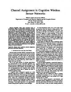
Figure 4. Histograms showing the VC balance for each dimension for different versions of the routing algorithm
4. Results
VC balance in x
16 14
To evaluate the effectiveness of each VC assignment policy we simulated several sizes of networks. We present results for an 11×12×16 torus. We define a metric, VC balance, which varies between 0 and 1. We compute VC balance for both synthetic workloads that assume uniform traffic, and we use real measurements from the SeaStar packet counters on each port. First, we define Pvc0 and Pvc1 as the number of packets on VC0 and VC1, respectively. Then, the VC balance for each link is simply:
version 1 version 2 version 3
number of links
12 10 8 6 4 2 0 0.25
|Pvc0 − Pvc1 | VC balance = Pvc0 + Pvc1
0.5
range
0.75
1
(a) X dimesnsion for kx =11
Thus if all packets are using only one virtual channel, the value of VC balance will be 1, and if the packets are evenly distributed across both channels, VC balance will be 0. We simulated a uniform traffic pattern on an 11×12×16 torus and computed VC balance on all links. The histograms shown in Figure 4 summarize the simulation results. In these histograms, we tabulate the number of links with 0 < VC balance ≤ 0.25 and put them in the first bin. Likewise, those links with 0.25 < VC balance ≤ 0.50 are in the second bin, and so forth. We do this for all three dimensions as show in Figures 4(a) thru Figure 4(c). The VC balance progressively improves with each modification to the original VC assignment policy. Version 3 improves the VC balance in the X dimension from 44%→27%, Y dimension from 42%→28%, and Z dimension from 42%→30%. Recall, a VC balance of 0.5 implies that one buffer has twice the packet load as the other. So, a VC balance that approaches zero is a figure of merit. Achieving uniform VC balance in a 3-D torus becomes increasing important as the radix grows, since network contention will also increase. Using the HPC Challenge [6] benchmarks, we have demonstrated increased throughput of 18.1% for MPIFFT (with 2048 PEs) and 17.4% for PTRANS (with 2016 PEs) relative to the initial VC assignment policy.
VC balance in y
16 14
version 1 version 2 version 3
number of links
12 10 8 6 4 2 0 0.25
0.5
range
0.75
1
(b) Y dimension for ky =12 VC balance in z
20 18 16
version 1 version 2 version 3
number of links
14 12 10 8 6 4 2
5
0
Conclusions
0.25
0.5
0.75
range
(c) Z dimension for kz =16
By multiplexing multiple virtual channels onto a single physical channel, we are able to achieve better throughput 6
1
tual dateline and multiple virtual channels are used to prevent toroidal deadlocks. However, this technique produces non-uniform VC buffer usage which is especially acute at and around the dateline node. We describe a progression of VC assignment policies that have improved the VC balance and ultimately the overall network performance. We demonstrate this with both simulation results and by running communication-intensive workloads from the HPC Challenge [6] benchmarks, MPIFFT and PTRANS, which both show increased throughput of 18.1% and 17.4%, respectively.
Acknowledgements We would like to thank the entire SeaStar development team and Cray XT packaging, benchmarking and software teams. We would also like to thank Pittsburgh Supercomputing Center (PSC) for their collaboration and willingness to try prototype software and early performance results.
References [1] M. Baxter. AMD64 Opteron: first look. Linux Journal, 2003(111):2, 2003. [2] R. Brightwell, K. T. Pedretti, K. D. Underwood, and T. Hudson. Seastar interconnect: Balanced bandwidth for scalable performance. IEEE Micro, 26(3):41–57, 2006. [3] W. J. Dally. Virtual-channel Flow Control. IEEE Transactions on Parallel and Distributed Systems, 3(2):194–205, 1992. [4] W. J. Dally and C. L. Seitz. Deadlock-free message routing in multiprocessor interconnection networks. IEEE Trans. Comput., 36(5):547–553, 1987. [5] C. J. Glass and L. M. Ni. The turn model for adaptive routing. In ISCA ’92: Proceedings of the 19th annual international symposium on Computer architecture, pages 278– 287, 1992. [6] HPCC Challenge Benchmarks. http://icl.cs.utk.edu/hpcc/. [7] IBM PowerPC 440 embedded cores. http://www03.ibm.com/chips/power/powerpc/. [8] P. Kermani and L. Kleinrock. Virtual cut-through: A new computer communication switching technique. Computer Networks, 3:267–286, 1979. [9] S. L. Scott. Synchronization and communication in the t3e multiprocessor. In ASPLOS-VII: Proceedings of the seventh international conference on Architectural support for programming languages and operating systems, pages 26–36, New York, NY, USA, 1996. ACM Press. [10] S. L. Scott and G. Thorson. Optimized routing in the cray t3d. In PCRCW ’94: Proceedings of the First International Workshop on Parallel Computer Routing and Communication, pages 281–294, London, UK, 1994. Springer-Verlag.
7