N.Ramesh Raju et al. / International Journal of Engineering and Technology (IJET)
Optimum Self Tuning of PID Controller Parameters for Level Control System against Parameter Variations by Neural Network trained with GA Optimized Data 1
N.Ramesh Raju*,2Dr.P.Linga Reddy
1 2
Professor,Dept. of EEE, SIET,Puttur,India,517583,Email:
[email protected] Professor,Dept. of EEE, KL Universty,Greenfields, Vaddeswaram, Andhrapradesh, India
ABSTRACT - PID controller is mostly used in process plants to control the system performance by properly choosing its parameters. The optimum PID parameters can be obtained in offline using genetic algorithm if the mathematical model of the system is exactly known. In all process plants the process parameters such as properties of materials like thermal conductivity, electrical conductivity, physical dimensions such as diameter, length of the pipes, parameters of valves and pumps will change as time runs. This happens due to corrosion, scaling, aging, repairs during the maintenance, wear and tear. When the system is robust these changes slightly affect the performance of the system. When the system is not robust they make the system performance worst. Due to above reasons the process plant parameters changes as time runs. It is not easy to measure the changes in system parameters while plant is running and could not be evaluated optimum PID parameters through mathematical model. In this paper a new approach using genetic algorithm and neural network is established for optimum self tuning of PID parameters by observing the time response of the system at any time while plant is running. Key words: parameter variation,Z-N method, GA,Neural Network, decay ratio, period of oscillations, PID controller, settling time,peak overshoot, integral square error, optimum tuning. 1. INTRODUCTION The tuning of PID parameter while plant is running normally has done through Z-N method or Process Reaction Curve method [1]-[2]. The parameters obtained through these methods are better but not optimum. Generally the optimum PID parameter setting is possible in offline using evolutionary optimization techniques and traditional optimization techniques, if mathematical model is available [3]-[6]. If the process parameters are known in on line, there are methods proposed to tune the PID parameters to optimum values, using fuzzy mapping rules built on data obtained through Genetic Algorithms (GA) [7]. In process plants the parameters are uncertain while running and hence exact mathematical model could not be evaluated. Sometimes even evaluated, modeling errors will present. The Data Driven PID controller proposed by Toru Yamamoto, Kenji Takao, and Takaaki Yamada in 2009 is new method to tune the PID controller parameters in online, but it will not assure optimum parameters[8]. Fuzzy PID controllers are also exist in literature and in practice for optimum performance [9]-[10]. This paper presents a new approach to tune the PID parameters near to optimum, using neural network, trained with optimized data obtained from genetic algorithm[11]. The binary coded genetic algorithm is developed to obtain the optimum PID parameters for changes in parameter values within +/- 40% interval, at fixed step covering the entire range. At the same time the time response for the set system parameters are obtained at constant proportional gain, period of oscillations and decay ratio of the time response for the step input are recorded. The gain is chosen such that the system produces under damped oscillations. Neural network training set contains period of oscillations and decay ratio as input and corresponding optimum PID parameters as output. The trained neural network is used to approximate optimum PID parameters once its time response parameters such as period of oscillations and decay ratio is fed through. This method partially depends on mathematical modeling but even then, if there is small modeling errors could not affect the optimization, since neural network is trained to give optimum PID parameters for system parameter variations of +/- 40% interval. 2. MODELING OF LEVEL CONTROL SYSTEM The level control system contains a valve to control the inflow of liquid into the tank and a tank with outflow of liquid as per the demand. Both valve and tank are first order systems. 2.1 MODELING OF VALVE The control valve, most of the times operated with pneumatic pressure to avoid fire hazards in the field. As pressure applied to the valve, the valve stem will be displaced and liquid flow throttled. When the pressure applied to the valve, the pressure inside the control valve chamber will not be raised to the applied pressure
ISSN : 0975-4024
Vol 7 No 5 Oct-Nov 2015
1716
N.Ramesh Raju et al. / International Journal of Engineering and Technology (IJET)
instantly. It will take time to raise the pressure to inlet pressure based on the volume of the chamber and restriction to the flow of air into the chamber. If we assume the volume of the valve chamber ‘V’ and pressure applied to the control valve is . according to the law of conservation of mass. ( )
− ( ) =
--------
(1)
Where Mass of air to be added to the valve chamber to raise unit pressure. Flow rate of air per unit pressure difference. Air Inlet pressure to the valve. ( )Pressure inside the chamber of the valve From the above differential equation (1) we can obtain the transfer function of the valve as follows ( )
=
( )
(2)
Where 1 / For linear control valve the flow rate through the valve is proportional to the position of the valve stem and stem position is proportional to the pressure inside the chamber of the valve. Hence ( )∝ ( ) (3) ( )
=
( )
(4)
Flow rate through the valve. 1 Steady state gain. 2.2 MODELING OF TANK SYSTEM Let us assume the inflow of water into the tank is conservation of mass
Where
−
and out flow from the tank is
. As per the law of
( )=
(5)
Where A Area of cross section of the tank ℎ Level of the tank ( )
( )=
(6)
R Resistance to flow out. From the above differential equation (5) it can be found that ( ) ( )
=
(7)
Where 2 = RA The control valve and tank are two non interacting systems cascaded in the control system. Hence ( ) ( )
∗
( ) ( )
=
( ) ( )
=
*
=(
)(
)
(8)
Where = 1 ∗ Steady state gain of the cascaded system. Hence the level of the tank (ℎ) is controlled by controlling the inlet pressure of the valve( ), which is the controller output. 2.3 TRANSFER FUNCTION OF LABORATORY MODEL The open loop transfer function of level control system of laboratory model is evaluated based on the closed loop response of the system as below. ( )=
(
.
)(
(9)
)
=3 1 = Time constant of the control valve = 62.5 seconds 2 = Time constant of the tank system = 435 seconds There is every possibility that time constants and steady state gain 1 , 2 and K to be changed. 1 may be changed due to changes in flow rate of air per unit pressure difference ( ) through the valve due to slight changes in the diameter of the pipe, length of the pipe and valve port dimensions . This happens in case of Where
ISSN : 0975-4024
Vol 7 No 5 Oct-Nov 2015
1717
N.Ramesh Raju et al. / International Journal of Engineering and Technology (IJET)
scaling of the pipe inside, repairs, wear and tear. Similarly the time constant 2 may be changed due to change in out flow restriction of the tank (R). Since ‘R’ is inversely proportional to the square root of level of the tank to be maintained, diameter of the out flow pipe and proportional to length of the pipe. Hence gain ‘ ’. 3. WORKING OF PROPOSED SYSTEM The proposed system uses closed loop time response of the system to set optimum parameters to PID controller. While tuning the system the closed loop gain Kp is set to fixed value, which gives under damped response for step input and Ki, Kd to zero. Keeping integral gain and derivative gain doesn’t affect the steady state response of the system. Since the integral output is remains same at steady state irrespective of gain due to zero error, similarly the derivative output is also zero due to constant error i.e zero. This process of tuning doesn’t affect the performance of the system under tuning. The time response of the system for small step input (3-5% of the reference) is monitored through computer and period of oscillations(To) and decay ratio (r) of the response is calculated. These two values are taken as input for the trained neural network to evaluate optimum PID parameters. The output of the neural network is set as PID parameters for present state of the system. Fig1 describes this process.
Fig:1 Block diagram of the proposed system
3.1 TUNING PROCEDURE While tuning the PID controller, the PID parameters Ki, Kd are kept zero and Kp to 15. Controller output does not change in this process, since at steady state the error is zero and unchanging hence the contribution to the controller output by proportional and derivative controller is zero and Integral controller holds it’s previous output. Integral controller holds sole responsibility for the controller output at steady state. Proportional gain Kp= 15 has been chosen for this system, since it produces damped oscillations in closed loop at this gain. R(S)
+
C(S)
(1 +
r(t)= 35 cm
1)(1 +
2)
Control Surface
Fig:2 Closed loop system while tuning
ISSN : 0975-4024
Vol 7 No 5 Oct-Nov 2015
1718
N.Ramesh Raju et al. / International Journal of Engineering and Technology (IJET)
A small step input (3-5% of reference) is introduced into the system as shown in Fig1. to find the time response parameters decay ratio (r ) and time period of damped oscillations (To). These parameters completely depends on system parameters as explained below The transfer function of the system shown in Fig2. is T(s) =
( ) ( )
=
∗ (
)(
)
(10)
∗
The system is second order system with steady state gain (Ks), natural frequency( ωn) and damping factor (ζ) as given below ∗
Ks=
∗
, ωn = (1 +
∗ )/ 1 2 , ζ =
( (
) ∗ )
The transient response parameters decay ratio (r) and time period of oscillations (To) of the system for step input is given by /√(
r=
)
(11) (12)
To = Substituting ωn and ζ in equations (11) and (12), we obtain r=
(
)/
(13)
To =
(14)
Where = sqrt(4(1 + ∗ ) 1 2 − ( 1 + 2) ) The equations (13) and (14) shows that the time response parameters ‘r’ and ‘To’ depends on system parameters ‘K’, 1 and 2. It means that if time response parameters are known, it gives the information about system parameters and then trained neural network find the optimal PID tuning through the inputs ‘r’ and ‘To’ 4. GENETIC ALGORITHM Genetic algorithms are inspired by Darwin’s theory that is survival of the fittest and it is an evolutionary algorithm for optimization of a mathematical procedure or rule. The mathematical procedure is represented as a fitness function to maximize. This algorithm is used in all the fields of science and social domains, if the problem can be represented in some mathematical sense. The algorithm uses three basic operators such as Reproduction, Crossover and Mutation for progressing optimization. Initially a set of population is produced in random manner. The fitness values are generated for the population and optimization process will proceed with three operators iteratively. In this paper fitness function is chosen as in (16) (15) Obj = αTs+βMp+γISE Since it is a minimization problem fitness function is F = 1/Obj (16) Where Obj ----------> Objective function Ts ------------> Settling time Mp ------------> Peak overshoot ISE -----------> Integral square error F -------------> Fitness function α, β, and γ are weighting factors. The above time response parameters Ts,Mp and ISE depends on PID controller parameters Kp,Ki and Kd . [Ts,Mp,ISE] = f(Kp,Ki,Kd) (17) Here the variables Kp,Ki and Kd represents the population and their values are coded in binary to implement binary coded genetic algorithm. The algorithm looks for Kp,Ki, and Kd values to minimize objective function. 4.1 REPRODUCTION It is the first operator applied on population. This process is adopted in genetic algorithm to pick best solutions and discard the worst solutions based on fitness values obtained through population. Retaining the best solution is based on probability and random procedure. This process sometimes retains worst solution hoping that after chromosomal exchange and genetic modification, it may produce best solution. In this paper
ISSN : 0975-4024
Vol 7 No 5 Oct-Nov 2015
1719
N.Ramesh Raju et al. / International Journal of Engineering and Technology (IJET)
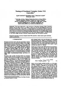
Roulette wheel selection is chosen as reproduction operator. The population retained in this process is called parents. 4.2 CROSSOVER Cross over is the process of chromosomal transfer from one parent to another parent, hoping that after chromosomal transfer a better child is produced (improved fitness value). The cross over has been done with some probability. In this paper the cross over probability is chosen as 0.125 4.3 MUTATION Mutation operator is used to introduce new chromosome into the population that may not possible to happen in cross over operation. This process flips the bit in the population whenever the random value generated between 0 and 1 is below the mutation probability. In this paper mutation probability of 0.25 is taken. In this paper training data for the neural network is obtained for the parameter variations in the range +/40% variations. Here the parameters are quantized at 20% steps in the variation range. The quantized system parameters are as given below. = {4.2,3.6, 3, 2.4 ,1.8}, 1= {87.5,75,62.5, 50,37.5} and 2 ={609,522,435, 348,261} Here the parameters are quantized into five levels. The possible combinations of these quantized parameters are 125 (5*5*5). The optimum PID parameters for these parameters are evaluated through Genetic Algorithm(GA) and at the same time response parameters ‘To’ and ‘r’ are recorded for the parameter set at Kp=15, which gives under damped oscillations for all possible parameter sets. Fig:3,Fig:4 and Fig:5 shows the data obtained from genetic algorithm for optimum values of PID parameters Kp,Kd and Ki respectively.
Fig:3 Surface fit plot for optimized Kp vs decay ratio(r) and period of oscillations(To)
Fig:4 Surface fit plot for optimized Kd vs decay ratio(r) and period of oscillations(To)
ISSN : 0975-4024
Vol 7 No 5 Oct-Nov 2015
1720
N.Ramesh Raju et al. / International Journal of Engineering and Technology (IJET)
Fig:5 Surface fit plot for optimized Ki vs decay ratio(r) and period of oscillations(To)
5. TRAINING OF NEURAL NETWORK Neural networks are well known as artificial intelligence systems[12]. When they are properly trained with examples from the past history of the behavior of any practical system, it is capable to predict new situations with success rate of 90-95%. In this paper the neural network is used to predict the optimum PID parameters against system parameter variations. Evaluation of the plant parameters when it is in operation not so easy, but the time response of the system entirely depends on the parameters. The parameters of time response of closed loop system such as period of damped oscillations and decay ratio are direct indicators of present system parameters(13)-(14), which can be easily evaluated while plant in operation as explained in 3.1. There exist 125 training vectors with To, r as input vector and optimum PID parameters (Kp,Ki,Kd), obtained through GA, as output vector. The neural network is trained with this data. The dimension of the neural network is 2-15-3. The Levenberg-Marquardt back propagation algorithm is used for training. 5.1 PERFORMANCE OF TRAINED NEURAL NETWORK The performance of neural network for untrained instances are evaluated for three cases as in Table:1. Table:1 Time response parameters for three cases considered
1 (sec)
Case
2 (sec)
r
To(sec)
1
3
68.75
391.5
0.0434
336.9
2
2.96
87.72
277.8
0.0053
333
3
4.12
82.64
400
0.0362
415.6
The Table:2 shows the performance comparison of the PID controller tuned by the trained Neural Network and tuned by GA for above three cases. It clearly indicates that the performance of the system with PID parameters tuned by neural network is close to the performance of the system tuned by GA in offline.
ISSN : 0975-4024
Vol 7 No 5 Oct-Nov 2015
1721
N.Ramesh Raju et al. / International Journal of Engineering and Technology (IJET)
Table:2
Case
PID parameters and time response tuned by trained NN Kp=16.52 Ki=0.00324 Kd=585.5
PID parameters and time response tuned by GA Kp=16.06 Ki= 0.0042 Kd=740
Mp=3.15% Ts =128 sec ISE =6.2*105 Kp=27.41 Ki=0.0063 Kd=1005
Mp=4.97% Ts =124 sec ISE =6.2*105 Kp=28.5098 Ki=0.0037 Kd=1081.2
Mp=8.81% Ts =227.5 sec ISE =5.86*105 Kp=27.84 Ki=0.0022 Kd=1061
Mp=6.86% Ts =211.7 sec ISE =5.86*105 Kp=27.49 Ki=0.0051 Kd=1178
Mp=14.85% Ts =291 sec ISE =5.98*105
Mp=6.74% Ts =230 sec ISE =5.85*105
Case1
Case2
Case3
6. SIMULATION RESULTS Simulation is performed on proposed system through MALAB/SIMULINK. The Fig:6 shows the performance of the PID controller tuned by Z-N method with no bound on control signal and the performance of the system tuned by GA with bound on control signal that the control signal should be always in the range 0100. Even though there is bound on control signal the performance of the GA tuned controller is better than the Z-N tuned case (without bound on control signal). Fig:7 shows the control signal in the two cases and it is observed that the control signal in unbounded case varies from -150 to 800. Negative actions of the controller do not take place in many process applications. It normally get saturated at zero control signal. It can be seen clearly that the control signal in second case is always lies in the limits 0-100.
Fig:6 Comparison of time response of the system for Z-N and GA tuned
ISSN : 0975-4024
Vol 7 No 5 Oct-Nov 2015
1722
N.Ramesh Raju et al. / International Journal of Engineering and Technology (IJET)
Fig:7 Comparison of control signal generated in Z-N tuned and GA tuned with bound on control signal (0-100)
Table:3 shows the performance of the proposed system in comparison with the PID parameters set fixed irrespective of the system parameter variation. When the parameters of PID controller are updated by trained neural network against parameter variations the performance of the system is better than the f PID parameters set fixed to optimum(Kp=21.3529,Ki= 0.0039,Kd=507.25) at =3, 1=62.5 and 2=435. Fig:8, Fig:9 and Fig:10 shows the time response of the proposed system for case1, case2 and case3 respectively. Table:3
Case
Kp=16.52 Ki=0.00324 Kd=585.5
Optimum PID parameters set fixed to initial system parameters ( =3, =62.5and =435) and system performance for changing system parameters Kp=21.3529 Ki= 0.0039 Kd=507.25
Mp=3.15% Ts =128 sec ISE =6.2*105 Kp=27.41 Ki=0.0063 Kd=1005
Mp=4.97% Ts =223 sec ISE =6.2*105 Kp=21.3529 Ki= 0.0039 Kd=507.25
Mp=8.81% Ts =227.5 sec ISE =5.86*105 Kp=27.84 Ki=0.0022 Kd=1061
Mp=13% Ts =252.6 sec ISE =5.94*105 Kp=21.3529 Ki= 0.0039 Kd=507.25
Mp=14.85% Ts =291 sec ISE =5.98*105
Mp=19.41% Ts =315 sec ISE =6.21*105
PID parameters tuned by NN based on time response for changing system parameters and system performance after tuning
Case1
Case2
Case3
ISSN : 0975-4024
Vol 7 No 5 Oct-Nov 2015
1723
N.Ramesh Raju et al. / International Journal of Engineering and Technology (IJET)
Fig:8 Time response comparison between fixed PID controller and PID controller optimized for parameter variations for CASE-1
Fig:9 Time response comparison between fixed PID controller and PID controller optimized for parameter variations for CASE-2
ISSN : 0975-4024
Vol 7 No 5 Oct-Nov 2015
1724
N.Ramesh Raju et al. / International Journal of Engineering and Technology (IJET)
Fig:10 Time response comparison between fixed PID controller and PID controller optimized for parameter variations for CASE-3
The above simulation results show that when the PID controller is tuned against parameter variation , it produce better time response compared to when the PID controller parameters are affix to optimum for initial parameter set of level control system. 7. CONCLUSIONS The proposed system is tested in MATLAB/SIMULINK environment and the results show that the PID controller is effectively adapting to the parameter variations. This system is insensitive to modeling errors, since the proposed system obtains the optimum PID parameters through time response, for parameter variations in the interval +/- 40% of initial parameters. This work facilitates optimum tuning of PID controller parameters in online against parameter variations, through neural network, trained with data optimized by evolutionary algorithm. The simulation result shows that the neural network system can produce optimal tuning of PID controller and this solves the problem associated with evolutionary computation techniques in applying to online applications. The proposed work is to be tested on practical work bench in future. REFERENCES [1]
J. G. Ziegler and N. B. Nichols, “Optimum settings for automatic controllers,”Trans. ASME, vol. 64, no. 8, pp. 759/768–759/768. 1942 [2] K. L. Chien, J. A. Hrones, and J. B. Reswick, “On the automatic control of generalized passive systems,” Trans. ASME, vol. 74, pp. 175/185–175/185. 1972 [3] Aytekin bagis, “Determination of the PID Controller Parameters by Modified Genetic Algorithm for Improved Performance”, Journal of information science and Engineering 23, p.p. 1469-1480. 2007 [4] Zwe-Lee Gaing, A Particle Swarm Optimization Approach for Optimum Design of PID Controller in AVR System” , IEEE Transactions On Energy Conversion, Vol. 19, No. 2. 2004 [5] D.E. Goldberg, “ Genetic algorithms”, Addison-Wisley. 1999 [6] Keyu Li “ PID Tuning for Optimal Closed-Loop performance with specified Gain and Phase Margins” IEEE Transactions on control Systems Technology, Vol. 21, No.3. 2013 [7] D. Devaraj B. Selvabala “Real-coded genetic algorithm” and fuzzy logic approach for real- time tuning of proportional–integral– derivative controller in automatic voltage regulator system”IET Gener. Transm. Distrib., , Vol. 3, Iss. 7, pp. 641–649, 2009 [8] Toru Yamamoto, Kenji Takao, and Takaaki Yamada, “Design of a Data-Driven PID Controller”, IEEE Transactions On Control Systems Technology, Vol. 17, No. 1. 2009 [9] George K. I. Mann, Bao-Gang Hu, and Raymond G. Gosine “Two-Level Tuning of Fuzzy PID Controllers” IEEE Transactions On Systems, Man, And Cybernetics— Part B: Cybernetics, Vol. 31, No. 2. 2001 [10] Teo Lian Seng, Marzuki Bin Khalid “Tuning of a Neuro-Fuzzy Controller by Genetic Algorithm” IEEE Transactions On Systems, Man, And Cybernetics—Part B: Cybernetics, Vol. 29, No. 2. 1999 [11] Goldberg D. “ Genetic Algorithms in Search, Optimization and Machine Learning’ Addison-wisley,1989 [12] Bart kosko., “Neural networks and fuzzy logic system”, PHI publications.
ISSN : 0975-4024
Vol 7 No 5 Oct-Nov 2015
1725