Aug 1, 2011 - possible to scale the TH-UWB radio system for low to moderate data .... The system performance of the orthogonal pulse based modulation ...
0 2 Orthogonal Pulse-Based Modulation Schemes for Time Hopping Ultra Wideband Radio Systems Sudhan Majhi1 and Youssef Nasser2 1 Electrical 2 Faculty
and Electronic Engineering, Nanyang Technological University of Engineering and Architecture, American University of Beirut 1 Singapore 2 Lebanon
1. Introduction Ultra wideband (UWB) radio is a promising technology for short range wireless communications. It can be used for both high rate and low rate transmissions. High data rate can be achieved by using multiband (MB)-UWB approach whereas low data rate with robust system performance can be obtained by employing time hopping (TH)-UWB radio systems Majhi et al. (2006); Win & Scholtz (1998a). Nowadays, applications of UWB are spreading to various fields such as vehicle communications, wireless sensor networks, ad hoc wireless networks, and controller area networks. The most of the systems require low to moderate (1 kbs-100 mbs) data rates with an acceptable implementation cost. However, due to the presence of fast Fourier transform (FFT) and inverse FFT (IFFT), MB-UWB may not be a cost effective procedure for low data rate systems. Therefore, one needs an efficient system which adaptively changes the data rate from low to moderate with robust system performance. TH-UWB with OOK-PSM modulation provides low data rate with robust system performance Majhi, Madhukumar, Premkumar & Richardson (2008). However, it is possible to scale the TH-UWB radio system for low to moderate data rates by incorporating higher level modulation schemes with an adaptive method. For TH-UWB systems, various M-ary modulation schemes such as pulse position modulation (PPM), pulse amplitude modulation (PAM), pulse shape modulation (PSM), and their combined forms have been proposed to improve data rates and system performance with low complexities Bin et al. (2003); Durisi & Benedetto (2003); Ghavami et al. (2002); Michell et al. (2003); Usuda et al. (2004). However, due to the increase of inter symbol interference (ISI) in the presence of multipath channel, M-ary PPM or M-ary orthogonal PPM (OPPM) are not effective for TH-UWB systems with RAKE reception when M is high Foerster (2003); Win & Scholtz (1998b). High-level M-ary PAM is rarely used in short range and low power consumption communications systems Guvenc & Arslan (2003). This is because that the Euclidian distances between constellations become small with increase in M. Due to its robustness against ISI and multiple access interference (MAI), pulse-based modulation such as PSM has become an interesting research topic in TH-UWB, direct sequence UWB (DS-UWB) and transmitted reference UWB (TR-UWB) radio systems Chu & Murch (2005); de Abrue et al. (2003); Gezici et al. (2006); Hwang et al. (2007); Kim & Womack (2007); Parr et al. (2003). However, high-level M-ary PSM cannot be used due to the limited auto correlation properties
www.intechopen.com
32
2
Novel Applications of the UWB Technologies Name of the Book
of higher order orthogonal pulses. Moreover, its system complexity increases linearly with order of pulse waveform Gezici & Kobayashi (2005); Harada et al. (2004). To deal with these challenges, combined modulation schemes such as M-ary biorthogonal PSM (BPSM), PPM-PSM, BPSK-PSM and OOK-PSM have been provided for M-ary TH-UWB systems Hu & Zheng (2005); Majhi, Madhukumar & Premkumar (2007); Majhi, Madhukumar, Premkumar & Chin (2007b); Michell et al. (2003); Usuda et al. (2004). However, M-ary BPSM still requires M/2 orthogonal pulses to transmit the signal. To improve system performance, PPM-PSM requires orthogonal coded modulation and memory at the receiver to maintain orthogonalities among the constellation vectors Mitchell & Kohno (2004). In the presence of multipath channel, BPSK-PSM and OOK-PSM cannot be used for higher level modulation scheme for higher data rates Majhi, Madhukumar, Premkumar & Chin (2007b); Usuda et al. (2004). In order to address these problems, a combined modulation scheme (OPPM-BPSM) for TH-UWB systems was provided by the first author of this chapter to increase system data rate with good system performance Majhi et al. (2011). The proposed scheme was a combination of orthogonal PPM (OPPM) and BPSM modulation. In this chapter, we provide TH-UWB system design based on orthogonal pulse waveform. To show the robustness of orthogonal pulse waveform for TH-UWB systems we have provided performance analysis, capacity analysis and power spectral analysis of various orthogonal pulse based modulation schemes. The rest of the chapter is organized as follows: section 2 describes used orthogonal pulses and its various modulation forms. Section 3 discusses system performance of OPPM-BPSM modulation schemes and its various interference issues. Section 4 provides the system capacity of TH-UWB systems for several orthogonal pulse based modulation schemes. Section 5 provides power spectral analysis of orthogonal pulse based modulation scheme of TH-UWB systems. Section 6 is provided for the simulation results. Section 7 provides the summary of chapter.
2. System model for TH-UWB One of the essential functions in TH-UWB systems is the representation of a message symbol by a short duration pulse waveform for signal transmission through air de Abrue & Kohno (2003); Hu & Beaulieu (2004). The pulse waveform is an important design consideration which can affect UWB system performance considerably. The successful deployment of high data rate indoor TH-UWB systems strongly depends on the development of pulse waveforms and modulation schemes. Because of the short pulse waveforms, UWB is capable of providing high data rates for short range wireless communication. The chapter describes orthogonal pulse based TH-UWB system. 2.1 Orthogonal pulses
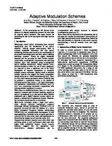
The commonly used orthogonal pulses for PSM modulation scheme are modified Hermite pulses (MHPs)Ghavami et al. (2002), Prolate spheroidal wave functions (PSWFs) Usuda et al. (2004), Battle-Lemarie wavelet orthogonal function Kim et al. (2005), and Haar wavelet orthogonal function Zhang & Zhou (2005). In this chapter all the analysis has been done based on MHPs and PSWFs. The system performance depends on autocorrelation and crosscorrelation properties. In addition, MAI is also reduced considerably by using crosscorrelation properties of orthogonal pulses. The time and frequency domain representation of MHPs are given in Fig. 1.
www.intechopen.com
Orthogonal Pulse-Based Modulation Schemes for Time Hopping Ultra Wideband Radio Systems Orthogonal Pulse-Based Modulation Schemes for Time Hopping Ultra Wideband Radio Systems
1
n=0 n=1 n=2
Amplitude
0.5
0
−0.5
−1 −10
−5
0 Time [ns]
5
0
n=0 n=1 n=2
−50 −100
Amplitude
10
−150 −200 −250 −300 −350 −400
0
2
4
6 8 Frequency [Hz]
10
12 9
x 10
Fig. 1. Time and frequency (logarithmic plot) domains representation of modified Hermite pulses (MHPs).
www.intechopen.com
333
34
Novel Applications of the UWB Technologies Name of the Book
4
2.2 M-ary Pulse Shape Modulation (PSM) In pulse shape modulation, a set of symbols is assigned by a set of orthogonal pulses which are orthonormal. The M-ary signal set for PSM can be written as ∞ � (k) (k) (k) Etx w(⌊ j/N ⌋%M) (t − jT f − c j Tc ) (1) s( k) (t) = ∑ j =− ∞
s
where {w0 (t), w1 (t), · · · , w M−1 (t)} is a set of orthogonal pulses and in general wi (t)⊥ wl (t) = 0 for i �= l and 1 for i = l in normalized form. M correlators and corresponding orthogonal pulses are used as a reference signal to detect M-ary signal at the receiver Usuda et al. (2004)Kim et al. (2005). Any mutually orthonormal pulses can be used for this modulation scheme. 2.3 M-ary Biorthogonal PSM
Biorthogonal PSM (BPSM) modulation is similar to BPM scheme, the only difference is that it is used for M-ary signaling . M-ary BPSM uses M/2 orthogonal pulses in the transmitter and M/2 correlators in the receiver to transmit all M possible symbols. The number of correlators or matched filters used in this scheme drops to half of those used in M-ary PSM scheme, thus reducing complexity of TH-UWB systems. An M-ary BPSM modulation has been proposed in Wen & Guoxin (2005). The output of an M-ary BPSM can be a signal with M/2 possible pulse shapes which are biorthogonal. Orthogonal pulse shapes are represented as follows: w0 (t), w1 (t), ..., w M/2−1 (t). The negative ones are defined as wi+ M/2 (t) = − wi (t), where i = 0, 1, ..., M/2 − 1. BPSM gives high data rate and makes it easier to map symbols into pulse waveforms. It has high power efficiency due to pulse polarity. However, similar to BPM scheme, it also requires two transmitters to generate BPSM signal. Maintaining bi-phase of orthogonal pulses is a challenging task. On the other hand, due to limitation of the possible number of orthogonal pulses it cannot be used for higher level modulation schemes. 2.4 M-ary OPPM-BPSM OPPM-BPSM scheme is a combination of orthogonal PPM and biorthogonal PSM (OPPM-BPSM). In order to transmit M symbols, one has to use L orthogonal pulse positions and N biorthogonal pulses where M = 2k , L = 2l , N = 2k−l −1, k > 1 and 0 ≤ l ≤ k − 1. Antipodal pulses are chosen to smooth the PSD of TH-UWB signal and to improve its coexistence ability with NB systems without any degradation in system performance Majhi, Madhukumar & Ye (2007). These biorthogonal pulses reduce the number of correlators in the receiver. Further, the system complexity is reduced by half when compared with a scheme that uses a combination of L pulse positions and N orthogonal pulses Kim et al. (2005). By changing the number of pulse positions and orthogonal pulses, one can construct a wide variety of symbols. For example, M-ary BPPM scheme can be constructed by using M/2 pulse positions and one biorthogonal pulse waveform, and M-ary BPSM scheme can be constructed by using one pulse position and M/2 biorthogonal pulses Wen & Guoxin (2005); Zhang & Gulliver (2005a). OPPM-BPSM scheme ensures relatively constant power envelope for transmitted symbol irrespective of the number of pulse positions and biorthogonal pulses. This multidimensional scheme increases the Euclidean distance of the transmitted signal, so power efficiency increases without affecting signal bandwidth Ramseier & Schlegel (1993). Since each position is able to transmit multiple orthogonal pulses, it does not require longer chip duration as well as longer time frame compared to M-ary OPPM or M-ary BPPM
www.intechopen.com
Orthogonal Pulse-Based Modulation Schemes for Time Hopping Ultra Wideband Radio Systems Orthogonal Pulse-Based Modulation Schemes for Time Hopping Ultra Wideband Radio Systems
355
schemes. Theoretically, N × L correlators are required in the receiver for M-ary OPPM-BPSM scheme, however, only N correlators with L delay units are sufficient to receive the signal. These delays can be implemented through software which reduces hardware complexity of M-ary OPPM-BPSM scheme for N < M.
3. Performance of M-ary OPPM-BPSM The system performance of the orthogonal pulse based modulation scheme decreases in the presence of multipath channel. The performance of OPPM-BPSM scheme is evaluated using the UWB multipath channel model based on the indoor channel measurement in the 2-8 GHz frequency band accepted by the IEEE802.15.3a study group Foerster (2003); Saleh & Valenzuela (1987). For simplicity, it is also assumed that signal is transmitted by using i th (0 ≤ i ≤ N − 1) order pulse in the q th (0 ≤ q ≤ L − 1) pulse position. Therefore the signal in Majhi, Madhukumar, Premkumar & Chin (2007a) can be rewritten as � (k) (k) (k) (k) (k) (k) (2) siq (t) = ∑ Etx dm wi (t − jT f − c j Tc − δq ) j
where dm ∈ {−1, 1}. If there are Nu users and each experiences a different channel model, the simplified received signal can be expressed as Nu L p
r (t) =
k =1 l =1
(k)
where τl model,
(k) (k) (k) siq (t − τl ) + n (t)
∑ ∑ αl
(3)
is the delay of path of kth user which takes values in the continuous time-invariant
(k) αl
is the l th path gain of kth user, and L p is the maximum number of paths among ( 1)
the users. It is assumed that the reference RAKE receiver is synchronized i.e. τl = 0 for l th RAKE finger of user 1. The receiver structure with RAKE fingers is shown in Fig.2. To receive the symbols, receiver requires L bank of correlators based on the L positions and each bank of correlators contains N correlators based on the order of orthogonal pulse. Further, each correlator contains RAKE fingers based on the number of estimated paths. The delay of the paths and fading are done by channel estimation. The reference signal in correlator of i th order pulse and q th pulse position of user 1 can be expressed as ( 1)
φiq (t) =
Ns −1
∑
j =0
( 1)
( 1)
( 1)
vi (t − jT f − c j Tc − δq )
(4)
where Ns is the number of pulse repetition interval for a symbol and ( 1)
vi (t) =
www.intechopen.com
Lp
( 1) ( 1) ( 1) wi (t − τp )
∑ αp p =1
(5)
36
Novel Applications of the UWB Technologies Name of the Book
6
Correlator bank for (L-1)th position
z00
Correlator for 1st order pulse
z10
...
Correlator for (N-1)th order pulse
...
r(t)
Correlator for 0th order pulse
arg max
Correlator bank for 0th position
Sign decision
...
Correlator bank for 1st position
M-ary symbol
z(N-1)0 (a)
Channel estimator
Weight estimator
wi(t-
³ dt wi(t-
³ wi(t-
zi0
...
r(t)
Path selection
³ dt
Lp)
Lp
dt
(b)
Fig. 2. Receiver structure for the OPPM-BPSM scheme (a) Block diagram for bank of correlators for the different pulse position and different order of orthogonal pulses. (b) Block diagram of correlators for 0th pulse position and i th (i = 0, 1, . . . , N − 1) order pulse which contains L p RAKE fingers for different delays and different weights
www.intechopen.com
377
Orthogonal Pulse-Based Modulation Schemes for Time Hopping Ultra Wideband Radio Systems Orthogonal Pulse-Based Modulation Schemes for Time Hopping Ultra Wideband Radio Systems
3.1 Decision statistics
At the receiver, the received signal, indicated as a useful signal, is corrupted by mainly three additive noise components: ISI noise generated due to multipath components, MAI due to presence of multiple users, and thermal noise generated in receiver antenna and receiver circuitry. The problem of receiver design can thus be stated as follows: Finding a good, when possible optimal, way for extracting a useful signal from the received signal. Solving the general problem is a complicated task that leads to complex receiver structures and requires good modeling of noise components. It is assumed that the receiver has perfect channel estimation and uses partial RAKE combining. At sample time t = ( j + 1) T f , the combined output of first L p paths of the correlator for i th order pulse and for q th pulse position can be written as Jia & Kim (2005); Jiang et al. (2005) ( 1)
ziq =
� ( j +1) T f jTf
( 1)
( 1)
r (t)φiq (t)dt ( 1)
( 1)
( 1)
= Siq + ISIiq + MAIiq + Niq ( 1)
( 1)
( 1)
(6) ( 1)
where Siq is the desired signal, ISIiq is the ISI term, MAIiq is the MAI term and Niq is the AWGN component of user 1 in the correlator of i th order pulse and q th pulse position. In order to improve detector performance of the system, effects of ISI and MAI have to be canceled before a symbol decision is made. In communication systems, decision feedback equalizers are commonly employed for this purpose. The main idea behind decision feedback equalization is that once a data symbol has been detected, the interference induces on the following symbols is estimated and subtracted out before the detection of subsequent symbols. Therefore, knowledge of the desired signal and interference noise is required to make correct decision. Gaussian approximation (GA) is not an appropriate method for finding the interference noise when a few multiple users are present in the system, However, due to its simplicity in the presence of multipath fading, this work assumes GA for the mathematical analysis for different noise terms Giorgetti & Chiani (2005). 3.2 Desired signal energy
The transmitted signal propagates in a multipath channel. To collect these multipath components, each correlator contains several RAKE fingers with different delays and weights. The desired multipath components are correlated with corresponding RAKE fingers, and some of these received energy are the desired or useful signal. In realistic scenarios it is assumed that pulses are orthogonal in a synchronized system. Therefore, the desired signal can be written as Majhi, Madhukumar, Premkumar & Chin (2007a) ( 1)
Siq =
�
( 1) ( 1)
Etr dm Ns
Lp
∑ p =1
� ( 1) �2 αp .
(7)
It is observed that the received energy in the multipath channel increases with increase in the number of RAKE fingers in the correlators, and this improves system performance. However, large number of RAKE fingers increases the system complexity and channel estimation error. Therefore, a minimum number of RAKE finger is used with considerable system performance. ( 1)
Since dm ∈ {±1}, the constellation distance in OPPM-BPSM is far from those in OOK-PSM scheme, which results in better system performance than that in OOK-PSM scheme.
www.intechopen.com
38
Novel Applications of the UWB Technologies Name of the Book
8
3.3 Inter Symbol Interference (ISI)
In the reality, channel is not perfectly estimated, and each path is not synchronized. So the decision variable is affected by other unexpected signals such as ISI. It occurs when multipath components are not received by their corresponding RAKE fingers, these are received by other RAKE fingers which have different weights and delays. The ISI noise of user 1 can be as Majhi, Madhukumar, Premkumar & Chin (2007a) ( 1)
2 1 = Etr Ns T − σISI f
Lp
Lp
Lp
Lp
( 1) ( 1) ( 1) ( 1) αl α p′ αl ′ X (Δ )
αp ∑∑ ∑ ∑ ′ ′
p =1 l =1 p =1 l =1 ′ p′ �= p l �=l
(8)
where X (Δ ) is the correlation function and Δ is the delay parameter detail given in Majhi, Madhukumar, Premkumar & Chin (2007a). It is observed that ISI is not reduced by orthogonal pulses and their modulation schemes. It depends on channel estimation and its delay spread. The channel delay spread cannot be controlled by modulation schemes or system design. The ISI can be reduced by increasing the duration of pulse repetition interval, which affects system data rates. On the other hand, duration of pulse repetition interval can be shorter when several orthogonal pulses are used in one pulse position but it reduces the system performance. This is one of many practical limitations for higher data rate systems with good system performance. 3.4 Multiple Access Interference (MAI)
In multiple access systems, several users transmit signals over the same channel. Pulses originating in other transmission links may interfere with pulses belonging to a reference transmission giving rise to MAI. The MAI noise of user 1 from Nu − 1 users can be written from Majhi, Madhukumar, Premkumar & Chin (2007a) as 2 1 = Ns T − σMAI f
Nu
(k)
Lp
Lp
Lp
Lp
( 1) ( k ) ( 1) ( k ) αl α p′ αl ′ Y (Δ ′ )
αp ∑ Etr ∑ ∑ ∑ ∑ ′ ′
k =2
p =1 l =1 p =1 l =1
(9)
where Y (Δ ′ ) is also a correlation function and Δ ′ is the delay parameter. The cross correlation value is smaller than the auto correlation values in both synchronous and asynchronous systems. It is observed that MAI depends on correlation properties of orthogonal pulses and number of users in the system. MAI is the sum of interference of one user from all the other users. When all the users use the same set of orthogonal pulses MAI is the sum of expectation of the product of auto correlation and cross correlation. In the conventional system this is expectation of product of auto correlation. Due to the presence of cross correlation term, MAI is reduced. However, when all the users use a different subset of orthogonal pulses, MAI is the sum of expectation of product of cross correlation which is the extreme case for better system performance. 3.5 Performance analysis
It is assumed that the correlator output ziq of i th order pulse and q th pulse position is larger than the other M/2 − 1 correlator outputs. As discussed before, each output is corrupted by 2 + σ2 2 2 noise and the total noise at each correlator can be defined as σISI MAI + σN where σN is AWGN. The corresponding average probability of a correct decision in the presence of ISI and
www.intechopen.com
Orthogonal Pulse-Based Modulation Schemes for Time Hopping Ultra Wideband Radio Systems Orthogonal Pulse-Based Modulation Schemes for Time Hopping Ultra Wideband Radio Systems
399
MAI can be expressed as Proakis (2001); Zhang & Gulliver (2005a) Pc =
� ∞ 0
�
� M −1 � z iq /√σ 2 +σ 2 +σ 2 2 N I SI MAI − x2 1 √ p(ziq )dziq exp dx √ 2 2 2 + σN2 2π −ziq / σI SI +σMAI
(10)
where probability density function of ziq can be written as
p(ziq ) = �
⎛ �
1
⎜ ⎜ exp ⎜− ⎝ 2 2 2 2π (σISI + σMAI + σN )
ziq − Ns
�
2 2(σISI
( 1)
L
p 1 2 Etr ∑ p= 1 (α p )
2 + σMAI
2) + σN
2 ⎞
The probability of a symbol error for combined M-ary OPPM-BPSM is given by PM = 1 − Pc .
⎟ ⎟ ⎟ ⎠
(11)
(12)
The BER of OPPM-BPSM scheme can be evaluated as Proakis (2001); Sklar (2001). Pb =
2k − 1 PM . 2k − 1
(13)
3.6 Simulation results
The orthogonal pulse based system has been extensively simulated in different channel conditions. Simulation results of an 8-ary TH-UWB system for different number of pulse positions and orthogonal pulses in the presence of IEEE 802.15.3a UWB multipath channel model Foerster (2003) is discussed in this section. Channel model corresponding to line of sight (0-4m) environment (CM1) is used for this study. The performance is analyzed by using two different sets of orthogonal pulses such as MHPs and PSWFs. Fig. 3 and Fig. 5 show the results of these simulation studies. The theoretical results are also provided for checking the validation of GA with these simulation studies. The solid lines represent performance for MHPs and dashed lines represent the performance for PSWFs. The performance of an 8-ary scheme is obtained by employing 1 position and 4 pulses, 2 positions and 2 pulses, and 4 positions and 1 pulse. In Fig. 3, the number of significant paths is decided by selecting paths within 10 dB of the strongest path. The performance is also evaluated using multi mode data rates, that is, duration of pulse position is fixed and duration of pulse repetition intervals is selected according to number of positions. The data rates of 1 position, 2 positions and 4 positions are 75 mb/s, 37.5 mb/s, and 18.75 mb/s, respectively for δ = 10 ns and Ns = 1. Since duration of pulse repetition interval increases with the increase in the number of positions, the inter frame interference is reduced. Therefore, the system performance with more pulse positions (4 positions 1 pulse) is better than the system performance with 1 position and 4 pulses. However, system with multiple pulse positions reduces the data rate correspondingly. On the other hand, system with 1 position and 4 pulses results in degraded performance due to speculative auto correlation properties of higher order pulses. Therefore, number of pulse positions and pulses can be selected adaptively based on the requirements of data rate and system performance. Fig. 5 shows the system performance of an 8-ary scheme for the same data rate (50 mb/s). Since pulse repetition interval is fixed for all possibilities of positions and pulses, length of each pulse position is decreased when 4 pulse positions and 1 pulse are considered. The
www.intechopen.com
40
Novel Applications of the UWB Technologies Name of the Book
10
BER vs Eb/N0 for 8ary scheme in multipath −10dB
0
10
1−position,4−pulses/BPSM 2−positions,2−pulses/proposed 4−positions,1pulse/BPPM 1−position,4−pulses/BPSM 2−positions,2−pulses/proposed 4−positions,1−pulse/BPPM
−1
10
−2
BER
10
−3
10
−4
10
−5
10
0
5
10
15
20
25
Eb/N0 [dB]
Fig. 3. Performance of 8-ary modulation scheme in different data rate by using modified Hermite and PSWF orthogonal pulses in multipath channel model where upto-10dB path is captured from peak point. BER vs Eb/N0 for 8−ary scheme in multipath 85%
0
10
1−position,4−pulses/BPSM 2−positions,2−pulses/proposed 4−positions,1−pulse/BPPM 1−position,4−pulses/BPSM 2−positions,2−pulses/proposed 4−positions,1−pulse/BPPM
−1
10
−2
BER
10
−3
10
−4
10
−5
10
0
5
10
15
20
25
Eb/N0 [dB]
Fig. 4. Performance of 8-ary modulation scheme in different data rate by using modified Hermite and PSWF orthogonal pulses in multipath channel model where 85% energy is captured.
www.intechopen.com
Orthogonal Pulse-Based Modulation Schemes for Time Hopping Ultra Wideband Radio Systems Orthogonal Pulse-Based Modulation Schemes for Time Hopping Ultra Wideband Radio Systems
41 11
BER vs Eb/N0 for 8ary scheme in multipath−10dB
0
10
1−position,4−pulses/BPSM 2−positions,2−pulses/proposed 4−positions,1−pulse/BPPM 1−position,4−pulses/BPSM 2−positions,2−pulses/proposed 4−positions,1−pulse/BPPM
−1
10
−2
BER
10
−3
10
−4
10
−5
10
0
5
10
15
20
25
Eb/N0[dB]
Fig. 5. Performance of 8-ary modulation scheme in the same data rate environment by using modified Hermite and PSWF orthogonal pulses in multipath channel model where upto-10dB path is captured from peak point. multipath signals of previous pulse positions affect the correlators of the next pulse position resulting in performance degradation. So the noise floor increases with SNR in the presence of ISI and MAI for a large number of pulse positions. The corresponding results is shown in Fig. 5 which shows that the large number of pulse positions (4 positions and 1 pulse) results in performance degradation. It has also been shown that moderate number of pulse positions and pulses (2 positions 2 pulses) is a better choice for an acceptable data rate and system performance. Since, auto correlation property of 0th order MHPs and 0th order PSWFs is the same, system with 4 positions and 1 pulse gives same performance for both pulses. However, difference in their auto correlation values increases with increase in the order of pulse, which results different performances for the use of higher order orthogonal pulses. Fig. 3 and Fig. 5 show that PSWFs pulses result in better performance than that of MHPs for more number of orthogonal pulses. Therefore, choice of orthogonal pulses also influences the system performance of pulse based modulation schemes.
4. Capacity of TH-UWB systems based on orthogonal pulse waveform In this section, we provide capacity for different modulation schemes for TH-UWB systems Majhi, Xiang, Madhukumar & Premkumar (2008). 4.1 Capacity of M-ary PSM scheme
For simplicity, a wireless channel is normally assumed to be constant within a coherence time and varies in the next coherence times. A symbol duration for a UWB signal, T f , is chosen as
www.intechopen.com
42
12
Novel Applications of the UWB Technologies Name of the Book
less than the channel coherence time. In an indoor environment, the delay spread of a UWB channel is much less than the channel coherence time Jiang et al. (2005); Zhang & Gulliver (2005b). The RAKE receiver scheme is adopted at the receiver to combine the total L p multi-path components (MPC) in following analysis. For a channel with a discrete-value input and a continuous-value output, a piece of k-bit information, U = {U1 , U2 , ..., Uk }, is mapped to a set of signals with M = 2k status of S = {S1 , S2 , ..., S M }, each of which, sn,PSM for the M-ary PSM scheme, can be simplified from (2) and represented as a M-dimensional signal vector. � (14) sn,PSM = [0, · · · , Etr , 0, · · · , 0]
where sn,PSM is a signal vector with a nonzero and nonnegative value at the n th position. The channel capacity can be derived by maximizing the mutual information between channel input and channel output, which is expressed as, C = max p(S) I (Y; S)
(15)
where I (Y, S) is the mutual information between the channel output Y and the channel input S. We assume that there is no restriction on input signal other than imposing an average power constraint. As the bandwidth increases, the data rate of a communications system over a multipath fading channel equals to the capacity of a system with an infinite bandwidth over an additive white Gaussian channel with the same SNR. The mutual information approaches close to zero where there are infinite numbers of MPC. This result holds even when the receiver can perfectly track the excess delay of each MPC and the only uncertainty lies on its phase and amplitude. Since S is the invertible function of U, the capacity becomes C = max p(S) I (Y; U).
(16)
Let z PSM be the channel output vector of M correlators which is corrupted by ISI, MAI and AWGN. After maximum ratio combination (MRC), zPSM can be expressed as a M-dimensional vector shown below. (17) z PSM = [ z1 , z2 , . . . , z M ] where zi = ISIi + MAIi + Ni for i �= n and zn = Sn + ISIn + MAIn + Nn for n th correlator. It is assumed that signal is transmitted by n th order pulse waveform where n ∈ {1, 2, . . . , M }. Since PSM constellations are in orthogonal space, the channel capacity with input signals restricted to an equiprobable M-ary PSM signal and with no restriction on the channel output is given by Li et al. (2005) � M � 1 M ∑k=1 p(z PSM | sk,PSM) dz PSM (18) p(z PSM | sn,PSM ) log2 CPSM = log2 M − ∑ M n=1 z PSM p(z PSM | sn,PSM ) where p(z PSM | sn,PSM ) is the probability density function (PDF) of zPSM , for a given sPSM . Since sPSM is dependant on the modulation scheme, the conditional PDF as well as system capacity vary with modulation scheme. To find the system capacity of M-ary PSM for TH-UWB systems, it is required to evaluate the PDF of M-ary PSM scheme. zPSM is a M dimensional joint Gaussian distribution random variable conditioned on sn,PSM with a PDF given by, � � � � � M/2 − (zn − Eb,PSM)2 M − z2i 2σ2 2σ2 1 p(z PSM | sn,PSM ) = . e (19) ∏e 2πσ2 i =1 i�=n
www.intechopen.com
Orthogonal Pulse-Based Modulation Schemes for Time Hopping Ultra Wideband Radio Systems Orthogonal Pulse-Based Modulation Schemes for Time Hopping Ultra Wideband Radio Systems
43 13
where the signal energy in multipath channel is obtained from (7) by substituting dm = 1 given as Lp � � ( 1) �2 (20) Eb,PSM = Etr Ns ∑ α p p =1
and
σ2
is the total noise and can be written as
2 2 2 σ2 = σISI + σMAI + σN .
(21)
Using (17) and (19) in (18), the channel capacity for an M-ary PSM scheme on a block fading channel is given as
CPSM
⎛
⎜ ⎜M − 1 M ⎜ = log2 M − Ez PSM |sn log2 ⎜ ∑ e ∑ ⎜ k =1 M n =1 ⎝
z2n − z2 + k
�
z k − Eb,PSM
2 � −
z n − Eb,PSM
2 ( σ2 + σ2 + σ2 ) I SI MAI N
2 ⎞ ⎟ ⎟ ⎟ ⎟ ⎟ ⎠
(22)
bits / channel use
It is observed that the bandwidth does not directly influence the mutual information, but it more likely depends on the level of modulation schemes and the total noise σ2 . This noise is directly related to the number of paths is shown in (8) and (9) . And if the underlying number of paths L p is very large and the delays of these paths spread out, L p will then increase with increasing bandwidth. The ISI can be reduced by increasing the duration of pulse repetition interval, which affects system data rates for M-ary PSM scheme as well as for M -ary BPSM scheme. It is also observed from (9) that MAI depends on the correlation properties of orthogonal pulses and the number of users. When all the users use pulses from a same set of orthogonal pulses, MAI is the sum of the expectation of the product of auto correlation function and cross correlation function. Hence, MAI is reduced for orthogonal pulse-based modulation due to the presence of cross correlation terms and this is true for all M-ary PSM, M-ary BPSM and M-ary OPPM-BPSM schemes. However, in conventional single pulse approach (pulse position modulation (PPM) and pulse amplitude modulation (PAM)), this is the expectation of the product of auto correlation functions Benedetto & Giancola (2004). It is well-known that a cross correlation function has a smaller value than that of an auto correlation function for orthogonal pulses Dilmaghani et al. (2003). 4.2 Capacity of M-ary BPSM scheme
In M-ary BPSM scheme, two symbols are transmitted by using only one orthogonal pulse. Therefore M-ary BPSM symbol vectors can be generated by using M/2-dimensional orthogonal space and expressed as smn,BPSM = [0, · · · , dm
�
Etr , 0, · · · , 0]
(23) n th
where smn,BPSM is a BPSM signal vector with nonzero value in the position, n ∈ {1, 2, . . . , M/2} and m ∈ ±1. Therefore, M-ary BPSM signal vectors are also in orthogonal space and dimension of signal remains the same as PSM scheme. However, the radius of the noise sphere for BPSM scheme becomes larger than the PSM scheme. It increases the system
www.intechopen.com
44
Novel Applications of the UWB Technologies Name of the Book
14
performance of BPSM scheme shown in Majhi, Madhukumar, Premkumar & Chin (2007a). Now the capacity of M-ary BPSM in multipath fading channel can then be expressed as
CBPSM=log2 M− ⎛
× log2 ⎝
1 2 M/2 ∑ M m∑ =1n=1
�
z BPSM
p (z BPSM | smn,BPSM)
M/2 ∑2j=1 ∑k=1 p(z BPSM | s jk,BPSM)
p(z BPSM | smn,BPSM)
where zBPSM is a M/2-dimensional vector defined as
(24)
⎞
⎠ dz BPSM
zBPSM = [ z1 , z2 , . . . , z M/2 ]
(25)
The joint Gaussian distribution of z BPSM conditioned on smn,BPSM is expressed as: � � � � � M/2 − (zm − Eb,BPSM)2 M − z2i 2 2 2σ 2σ 1 p(z BPSM | smn,BPSM) = e ∏e 2πσ2 i =1
(26)
i�= j
where the signal energy of BPSM in a multipath channel is obtained from (7) as Lp
Eb,BPSM =
�
Etr Ns dm
∑ p =1
� ( 1) �2 αp
(27)
Substituting (25) and (26) into (24), the capacity for an M-ary BPSM scheme over a fading channel is given as
CBPSM
⎛
⎜ ⎜ 2 N − 1 2 M ⎜ = log2 M − Ez BPSM|smn log2 ⎜ ∑ ∑ e ∑ ∑ ⎜ j =1 k =1 M m =1 n =1 ⎝
z2n − z2 + k
�
z k − Eb,BPSM
2 � −
2 ⎞
z n − Eb,BPSM
2 ( σ2 + σ2 + σ2 ) I SI MAI N
⎟ ⎟ ⎟ ⎟ ⎟ ⎠
bits / channel use (28) The effects of ISI and MAI of M-ary BPSM are similar as M-ary PSM scheme. However, the complexity of transceiver for BPSM scheme is reduced by half with respect to PSM scheme for M > 2. Moreover, BPSM scheme is capable of providing better system performance and capacity by improving the received signal power Majhi, Madhukumar, Premkumar & Chin (2007a).
www.intechopen.com
Orthogonal Pulse-Based Modulation Schemes for Time Hopping Ultra Wideband Radio Systems Orthogonal Pulse-Based Modulation Schemes for Time Hopping Ultra Wideband Radio Systems
45 15
4.3 Capacity of M-ary OPPM-BPSM scheme
M-ary OPPM-BPSM signal is constructed by using L orthogonal pulse positions and N orthogonal pulses. Therefore, OPPM-BPSM signal can be represented by a N × L-dimensional signal matrix shown below. ⎞ ⎛ ··· 0 0 0 0 ⎟ ⎜ . ⎜ 0 .. ··· 0 0⎟ ⎟ ⎜ ⎜. .. ⎟ √ ⎟ . S= ⎜ ⎜ . 0 dm Etr . 0 ⎟ ⎟ ⎜ ⎜ .. ⎟ ⎝0 ··· . 0⎠ 0 ··· 0 0 0 0
√ where dm Etr is a signal amplitude at l th row n th column. Since matrix has only one nonzero element, for simplicity, the input signal matrix can be expressed as a NL array signal vector, � (29) smnl = [0, · · · , dm Etr , 0, · · · , 0]
At the receiver there are NL correlators. Therefore, the received signal can be expressed as a LN array vector zOPPM− BPSM = [ z11 , · · · , z1L , z21 , · · · , z NL ] (30)
where zij = ISIij + MAIij + Nij for (i, j) �= (n, l ) and znl = Snl + ISInl + MAInl + Nnl . Similarly, the M-ary OPPM-BPSM modulation scheme for TH-UWB has discrete-valued inputs and continuous-valued outputs, which impose additional constraints on the capacity calculation. Therefore, the capacity for a UWB system using M-ary OPPM-BPSM can be expressed as N L 2 1 p ( zOPPM− BPSM| smnl ) ∑ ∑ 2NL m=1 n=1 l∑ =1 zOPPM− BPSM (31) � 2 � ∑ j=1 ∑kN=1 ∑ Lp=1 p(zOPPM− BPSM| s jkp ) × log2 dzOPPM− BPSM p(zOPPM− BPSM| smnl )
COPPM− BPSM = log2 M −
�
If it is assumed that signal is transmitted by using n th order pulse at l th pulse position, the joint Gaussian distribution of zOPPM− BPSM conditioned on smnl can be expressed as ⎛ ⎞ NL ⎜ N L � 2 2 z ⎟ (z − E − BPSM) 1 ⎜ − 2σj p2 ⎟ − nl b,OPPM 2σ2 e e p(zOPPM− BPSM| smnl ) = (32) ⎜ ⎟ ∏ ∏ ⎝ i =1 j =1 ⎠ 2πσ2 ( i,j )� = ( n,l )
where the signal energy over a multipath Majhi, Madhukumar, Premkumar & Chin (2007a)
channel Lp
Eb,OPPM− BPSM =
�
Etr Ns dm
∑ p =1
Substituting (30) and (32) into (31), the capacity is given as
www.intechopen.com
is
� ( 1) �2 αp
obtained
from (7)
as
(33)
46
Novel Applications of the UWB Technologies Name of the Book
16
1 2 N L ∑ ∑ EzOPPM− BPSM|smnl 2NLm∑ =1n=1l =1 ⎛ � 2 �
COPPM− BPSM=log2 M −
⎜ ⎜ 2 N L − ⎜ × log2 ⎜ ∑ ∑ ∑ e ⎜ j=1k=1i=1 ⎝
z2 − z2 + nl ki
z ki − Eb,OPPM − BPSM
−
2 ⎞
z nl − Eb,OPPM − BPSM
2 ( σ2 + σ2 + σ2 ) I SI MAI N
⎟ ⎟ ⎟ ⎟ ⎟ ⎠
(34)
bits / channel use
In M- ary PSM and M-ary BPSM scheme, ISI is reduced only by reducing pulse repetition interval which limits the system data rate. In M-ary OPPM-BPSM scheme, the duration of pulse repetition interval can be reduced by using several orthogonal pulses in one pulse position. However, this process reduces the system performance for higher values of M. This is a practical limitation for high data rate systems and we need to select a suitable value of M in an actual system design. 4.4 Simulation results
In these simulation studies, the capacities of a UWB system adopting M-ary PSM, M-ary BPSM and M-ary OPPM-BPSM modulation schemes are investigated over the modified IEEE 802.15.3a UWB multipath channel model, where M=4, 8, 16 and 32. The capacity is shown in terms of bits per channel use. For the clear understanding, the system capacity in multipath environment is provided in Fig. 6, Fig. 7 and Fig. 8. The system capacities of M-ary PSM, M-ary BPSM and M-ary OPPM-BPSM for M = 4 and 8 are provide in Fig. 6. Although, 8-ary PSM, 8-ary BPSM are the specific schemes of 8-ary OPPM-BPSM, 8-ary OPPM-BPSM outperform 8-ary PSM and 8-ary BPSM. It is because they use different pulse repetition intervals due to their different number of pulse positions and pulses. 4-ary BPSM and 4-ary OPPM-BPSM are identical since both use 1 positions and 2 pulses. It is also observed that at low SNR 4-ary OPPM-BPSM provide better system capacity than the 8-ary PSM scheme. It means that higher level PSM scheme does not provide good system capacity at low SNR. The capacities of 16-ary PSM, 16-ary BPSM and 16-ary OPPM-BPSM schemes are provided in Fig. 7. 16-ary OPPM-BPSM scheme can be designed in 4 ways such as by using 1 position, 2 positions, 3 positions and 4 positions. 16-ary BPSM is a specific scheme of 16-ary OPPM-BPSM when number of pulse position is 1. The system capacity of the OPPM-BPSM scheme increases with decrease in the number of pulse positions when modulation uses combined of OPPM and BPSM. However, in terms of performance, the system performance decreases with the decrease in the number of pulse positions for a given value of M as shown in our previous work Majhi, Madhukumar, Premkumar & Chin (2007a). Therefore, modulation scheme is to be designed based on capacity and performance requirement of the system. The capacities of 32-ary PSM, 32-ary BPSM and 32-ary OPPM-BPSM schemes for two different orthogonal pulse sets are provided in Fig. 8. It is observed that PSWFs provide better system capacity than MHPs. It is because of the PSWFs provides less ISI and MAI than the MHPs due to better autocorrelation properties of PSWFs. Therefore, the design of an orthogonal pulse becomes critical to increase the capacity of orthogonal pulse based UWB systems. However, for 32-ary BPPM scheme, PSWFs and MHPs provide the same system capacity. It is because
www.intechopen.com
Orthogonal Pulse-Based Modulation Schemes for Time Hopping Ultra Wideband Radio Systems Orthogonal Pulse-Based Modulation Schemes for Time Hopping Ultra Wideband Radio Systems
Capacity of 8−ary & 4− ary schemes in multipath environments 5 8−ary 8−ary 8−ary 4−ary 4−ary
4.5
OPPM−BPSM (2 positions, 2 pulses) BPSM PSM BPSM/OPPM−BPSM PSM
4
bits/channel use
3.5
3
2.5
2
1.5
1
0.5
0 −5
0
5
10
15
20
25
30
Eb/N0
Fig. 6. The capacities of M-ary PSM, M-ary BPSM and M-ary OPPM-BPSM schemes in a multipath environment where M=4 and 8. Capacity of 16−ary scheme in multipath environments 5
4.5
4
bits/channel use
3.5
3
2.5
2
1.5
1 16−ary 16−ary 16−ary 16−ary
0.5
0 −5
0
5
10
15
OPPM−BPSM(2 positions, 4 pulses) OPPM−BPSM( 4 positions, 2 pulses) BPSM PSM 20
25
30
Eb/N0
Fig. 7. The capacities of 16-ary PSM, 16-ary BPSM and 16-ary OPPM-BPSM schemes in multipath environment.
www.intechopen.com
47 17
48
Novel Applications of the UWB Technologies Name of the Book
18
we have used 1st order PSWF and 1st order MHP in 32-ary BPPM. It is known that both the pules provide exactly the same correlation properties for the 1st order pulse. Fig. 6, Fig. 7 and Fig. 8 show that the average full capacity for all values of M for M-ary PSM is nearly achieved where the SNR is close to 23 dB, 20 dB for M-ary BPSM and 17 dB for M-ary OPPM-BPSM. It is also observed that M-ary OPPM-BPSM has 3 dB more SNR than M-ary BPSM and 6 dB greater SNR than M-ary PSM at the same capacity. This is because of the use of orthogonal pulses resulting in that ISI and MAI are less for M-ary OPPM-BPSM scheme than M-ary PSM and M-ary BPSM schemes for the same value of M. However, after 25 dB SNR, the capacities are close to the same irrespective of the modulation schemes. Under the same simulation condition the system capacities of 16-ary BPPM, 16-ary PSM, 16-ary BPSM and 16-ary OPPM-BPSM as a function of number of MPC are provided in Fig. 9. It has been observed that capacities for all schemes decrease with increase in the number of MPC. This is because ISI and MAI increase with the increase in the number of MPC, resulting in the reduction of mutual information. It proves that mutual information is inversely proportional to number of MPC. It is also observed that BPPM and OPPM-BPSM are more sensitive to the number of MPC. When number of MPC is more than 10, the capacities of BPPM and OPPM-BPSM are decreased more gradually than the PSM and BPSM scheme. It is because of involving pulse position modulation in both BPPM and OPPM-BPSM. Indeed, it is known that pulse position modulation is more sensitive in multipath environment. However, OPPM-BPSM still outperforms conventional BPPM scheme for the same values of M.
5. Power spectral analysis of TH-UWB systems In orthogonal pulse based signal, different symbols are transmitted by different order orthogonal pulses. The continuous spectrum, energy spectral density (ESD), changes with symbol. The discrete spectral component changes with orthogonality of the pulses and TH code. Therefore, a mathematical frame work is essential to understand the orthogonal pulse based PSD in the presence of deterministic TH code Majhi et al. (2010). We assume that the analysis is only for 1 user. For simplicity, the superscript/subscript terms in (35) are omitted/modified. After some modification, sum of M symbol can be written from (2) as s p (t) =
M −1 Ns −1
∑ ∑
l =0 h =0
al wl (t − l Np T f + hT f − cl,h Tc − δl )
(35)
where al is the amplitude and δl is the pulse position. The terms al , δl and wl are independent and stationary process. The index p is related to TH code, cl,h , and TH period, Np . To simplify the analysis of the PSD of TH-UWB signal, it is assumed that the number of time frames for a symbol is Ns and it is equal to Np . Since (35) depends on the time dithering, it can be written in continuous form as (36) y ( t ) = ∑ s p ( t − l Np T f ). l
The PSD is computed by evaluating the Fourier transform (FT) of the autocorrelation function of y(t) i.e. � � Py ( f ) = F E {y(t)y(t + τ )}
www.intechopen.com
(37)
Orthogonal Pulse-Based Modulation Schemes for Time Hopping Ultra Wideband Radio Systems Orthogonal Pulse-Based Modulation Schemes for Time Hopping Ultra Wideband Radio Systems
49 19
Capacity of 32−ary scheme for PSWFs & MHPs 5
4.5
4
bits/channel use
3.5
3
2.5
PSWFs MHPs
2
1.5
1 32−ary 32−ary 32−ary 32−ary 32−ary
0.5
0 −5
0
5
10
OPPM−BPSM (8 positions, 2 pulses) OPPM−BPSM (2 positions, 8 pulses) BPSM PSM BPPM
15
20
25
30
Eb/N0
Fig. 8. The capacity of 32-ary PSM, 32-ary BPSM and 32-ary OPPM-BPSM schemes schemes in a multipath environment with different sets of orthogonal pulse waveforms. Capacity vs multipath component 4 16−ary 16−ary 16−ary 16−ary
3.5
OPPM−BPSM BPSM PSM BPPM
Capacity bits/channel use
3
2.5
2
1.5
1
0.5
0 0 10
1
10 Number of multipath components
2
10
Fig. 9. The capacity versus multipath components is provided for 16-ary BPPM, 16-ary PSM, 16-ary BPSM and 16-ary OPPM-BPSM schemes.
www.intechopen.com
50
Novel Applications of the UWB Technologies Name of the Book
20
where F {.} denotes the FT and E {.} denotes the expectation operator. Therefore, the PSD can be expressed as Padgett et al. (2003) � � � � �� 1 E | S p ( f )|2 − E S p ( f )Sq∗ ( f ) Py ( f ) = Np T f (38) � � � k 1 ∗ E S p ( f )Sq ( f ) δ f − + Np T f ( Np T f )2 ∑ k where p and q are two independent random variables with the same probability distribution function. S p ( f ) is the FT of s p (t). It can be expressed as M −1
∑
Sp ( f ) =
Wl ( f ) Tl ( f ) al e− j2π f δl
(39)
l =0
where Wl ( f ) is the FT of the transmitted pulse wl (t). The time domain representation of (l + 2)th order MHPs can be expressed as nwl +2 (t) = 2twl +1 (t) − 2(l + 1)wl (t)
(40)
The FT of wl +1 ( f ) can be expressed as Wl +1 ( f ) = j
�
1 ˙ W ( f ) − 2π f Wl ( f ) 4π l
�
(41)
where “ ˙ ” stands for derivative with respect to frequency. For MHP, W0 ( f ) is defined as
√ 2 2 W0 ( f ) = 2 πe−4π f
(42)
The time and frequency domain representation of MHPs are given in Fig. 1. Tl ( f ) is the FT of the TH code which transmits the l th symbol Tl ( f ) =
Ns −1
∑
e− j2π f (c l,h Tc +( l Np +h) Tf ) .
(43)
h =0
To find the closed form expression of Py ( f ) in (38), the expectation of | S p ( f )|2 is to be evaluated. It is given as � � M −1 M −1 � E | S p ( f )|2 =E ∑ ∑ Wl ( f )Wn ( f )∗ Tl ( f ) l =0 n =0
(44) �
× Tn ( f )∗ al an e− j2π f (δl −δn ) . Since al and an are independent random variables derived from the same process and δl and δn are independent random variables derived from different processes. Therefore, (44) can be
www.intechopen.com
Orthogonal Pulse-Based Modulation Schemes for Time Hopping Ultra Wideband Radio Systems Orthogonal Pulse-Based Modulation Schemes for Time Hopping Ultra Wideband Radio Systems
51 21
rewritten as � � E | S p ( f )|2 =
M −1 �
∑
l =0
M −1
∑
|Wl ( f )|2 | Tl ( f )|2 E { a2l }+ Wl ( f )Wn∗ ( f ) Tl ( f ) Tn∗ ( f )
n =0 n�=l
× E{ al } E{ an } E{e
− j2π f ( δl − δn )
(45) �
} .
Similarly, the second expectation in (38) can be expressed as E {S p ( f )Sq∗ ( f )}=
M −1 M −1
∑ ∑
Wl ( f )Wn∗ ( f ) Tl ( f ) Tn∗ ( f )
l =0 n =0
× E { al } E{ an } E
�
e− j2π f (δl −δn )
�
(46)
.
The waveforms s p (t) and sq (t) are generated by two i.i.d processes. Therefore, the expectation in (46) is independent of l and n and equal to the case l �= n of (45) i.e. E {S p ( f )Sq∗ ( f )} = E { al } E { an } E {e− j2π f ( δl −δn ) }
×
M −1 M −1
∑ ∑
Wl ( f )Wn∗ ( f ) Tl ( f ) Tn∗ ( f )
(47)
l =0 n =0
Substituting (45) and (47) in (38), the final PSD can be formulated as in (48)
Py ( f ) =
E { a2l } − E { al } E { an } E {e− j2π f ( δl −δn ) } M−1 ∑ |Wl ( f )|2 | Tl ( f )|2 Np T f l =0
� E { al } E { an } E {e− j2π f ( δl −δn ) } M−1 M−1 k ∗ ∗ + ∑ ∑ Wl ( f )Wn ( f )Tl ( f )Tn ( f ) ∑ δ f − Np T f ( Np T f )2 k l =0 n =0 (48) Although UWB signals are alike in the frequency domain, they are diverse in the time domain due to their different characteristics of time domain parameters Np , T f , al and wl . We see that the PSD of orthogonal pulse-based modulation signals consists of continuous and discrete spectral components which change with the order of pulse waveforms and modulation schemes. The variation of PSD over different orthogonal pulse-based signaling are given in the following section. 5.1 PSD of M-ary PSM scheme
In PSM scheme, symbols are modulated only by the order of orthogonal pulses. The generalized terms in (48) are specified by al =1 and δl = 0. The expectations of these variables are E { a2l } = 1, E { al } E { an }l �=n = 0 and E {e− j2π f ( δl −δn ) } = 1 respectively. The PSD of the PSM signal can be written from (48) as Py ( f ) = p( f ) + pk ( f )
www.intechopen.com
(49)
52
Novel Applications of the UWB Technologies Name of the Book
22
where 1 Np T f
p( f ) =
M −1
∑
l =0
|Wl ( f )|2 | Tl ( f )|2
(50)
and pk ( f ) =
M −1 M −1 1 ∑ Wl ( f )Wn∗ ( f )Tl ( f )Tn∗ ( f ) 2 ( Np T f ) l∑ n =0 =0 � k ×∑δ f − Np T f k
(51)
We see that p( f ) is continuous spectrum component. It depends on the TH code and the ESD of the l th order orthogonal pulse. Since ESD of different order orthogonal pulses are not identical, the selection of order of the orthogonal pulses plays an important role for continuous spectral component. pk ( f ) is the discrete spectral component which induces UWB interference on the other narrow band systems Majhi, Madhukumar � & Ye (2007). The discrete components of the signal appear based on the term ∑k δ f −
k Np T f
. It shows that the position of discrete component depends
on the TH code and its dynamic range of amplitude depends on the orthogonality of pulses. Since pulses are orthogonal in time and frequency domains, the value of Wl ( f )Wn∗ ( f ) is approximately zero, as a result, the dynamic range of amplitude of the discrete spectral components becomes very small. This small dynamic range increases the average transmitted power in pulse and improves the UWB system performance. It helps UWB signal to coexist with other systems without any serious performance degradation. In addition, it facilitates UWB signal to keep its spectrum under the FCC spectral mask without minimizing the average transmitted power in the signal. 5.2 PSD of M-ary BPSM scheme
In BPSM scheme, symbols are modulated by order and amplitude of the pulses, i.e. al ∈ {±1} and δl = 0. The expectation of these variables are E { a2l } = 1, E { al } E { an }l �=n = 0 and E {e− j2π f ( δl −δn ) } = 1. The corresponding PSD of BPSM scheme can be expressed from (48) as Py ( f ) =
1 Np T f
M −1 Ns −1 Ns −1
∑ ∑ ∑
l =0 h =0 k =0
�
|Wl ( f )|2
� �� × exp − j2π f (cl,h − cl,k ) Tc + (h − k) T f
(52)
The continuous PSD component of BPSM signal is same as PSM scheme. However, the discrete spectral components become zero due to the antipodal pulse. The PSD of the TH-UWB signal for BPSM scheme is smoothed. This allows the signal to coexist with other NB signals. The extensive studies found that any antipodal signal has only continuous spectral component Majhi, Madhukumar & Ye (2007). The continuous component can be easily fitted to FCC by using appropriate MHPs.
www.intechopen.com
Orthogonal Pulse-Based Modulation Schemes for Time Hopping Ultra Wideband Radio Systems Orthogonal Pulse-Based Modulation Schemes for Time Hopping Ultra Wideband Radio Systems
53 23
−30 FCC PSD
Amplitude of dynamic range =8 dB −40
PSD in dBm/MHz
−50
−60
−52 −53
−70
−54 −55 −56 −80
−57 −58 8
8.5
9 9
x 10 −90
0
2
4
6 Frequency [Hz]
8
10
12 9
x 10
Fig. 10. PSD of 8-ary OPPM scheme with 3rd order MHP and TH code length is 8. 5.3 PSD of M-ary OPPM-BPSM scheme
For OPPM-BPSM scheme, al ∈ {±1} and δl = (l − 1)δ, where δ is the constant time shift length. This implies, E { a2l } = 1, E { al an } = 0 and E {e− j2π f mTΔ δ } = (1 + cos(2πm f TΔ ))/2. The corresponding PSD of OPPM-BPSM signal can be expressed as Py ( f ) =
1 Np T f
M −1 Ns −1 Ns −1
∑ ∑ ∑
l =0 h =0 k =0
|Wl ( f )|2
(53)
�
� �� × exp − j2π f (cl,h − cl,k ) Tc + (h − k) T f
The PSDs of BPSM and OPPM-BPSM schemes are identical. However, OPPM-BPSM can be used for higher level modulation scheme for higher data rate systems. Therefore, OPPM-BPSM modulation is an attractive choice of TH-UWB signal from several aspects.
6. Simulation results and discussions In this section, PSD is provided for orthogonal pulse-based signaling and compared with conventional OPPM scheme. In simulation, different order of MHPs are used with two different lengths of TH code 8 and 16. The other simulation parameters are set to T f = 60 ns and pulse width is 0.7ns. Since BPSM and OPPM-BPSM have antipodal signal, they have only continuous spectral component and shape of their spectral is same as continuous component of non antipodal signal. The only difference is that spectral of antipodal signal does not contain any discrete component. The PSD in non antipodal modulation schemes is more complicated. Since OPPM and OPPM-PSM are special cases of OPPM-BPSM, OPPM and OPPM-PSM have been chosen
www.intechopen.com
54
Novel Applications of the UWB Technologies Name of the Book
24
−30 FCC PCD
PSD in dBm/MHz
−40 −50 −60 −70 −80 −90
0
2
4
−30
6 Frequency [Hz]
8
10
9
FCC PCD
−40
PSD in dBm/MHz
12 x 10
−50 −60 −70 −80 −90
0
2
4
6 Frequency [Hz]
8
10
12 9
x 10
Fig. 11. (a) PSD of 8-ary OPPM scheme with 4th order MHP. (b) PSD of 8-ary OPPM scheme with 5th order MHP and TH code length is 8 to compare the PSD of the signal. The PSD of 8-ary OPPM is given in Fig.10 for 3rd order pulse and in Fig.11 for 4th and 5th order pulses with TH code of length 8 and Tc = 7.5ns. Since each time only one pulse is used in OPPM scheme, orthogonality is maintained by position not by pulse. The 3rd order pulse almost satisfy the FCC spectral mask except some discrete components. However, 4th and 5th order pulses do not satisfy the FCC spectral mask shown in Fig.11. The dynamic range of the amplitude of discrete components of OPPM scheme is about 8 dB which is very high. The power of the signal is calculated based on the line where the dynamic range is zero (4 dB below from the pick point). As FCC rules, pick amplitude must be below the -41.25 dBm limit. Therefore, the power of the signal is calculated based on the line which is maximum up to -45.25 dBm. As a result, signal provides low average transmitted power which degrades the system performance. Not that if the dynamic range becomes zero, the maximum limit becomes -41.25 dBm. Fig. 12 shows the PSD of 8-ary OPPM-PSM for 4 positions and 2 orthogonal pulses with TH code of length 8. We see that that dynamic range of the amplitude of the discrete spectral component of OPPM-PSM scheme is 4 dB which is lower than the OPPM scheme even the same length of TH code is used. It is because of the orthogonality of pulses. So by reducing dynamic range, we can improve the UWB system performance by increasing the average transmitted power in the signal pulse as well as we can reduce the UWB interference over other radio systems. Again by applying TH code over these orthogonal pulse-based modulation, dynamic range of amplitude of discrete component further could be reduced. Fig. 13 shows the PSD of 8-ary OPPM-PSM with TH code of length 16 and Tc = 3.75ns. The dynamic range is almost reduced to 1 dB. However, it can not be reduced to zero whatever the length of TH code used. We also see that the average transmitted power in Fig. 13 is more
www.intechopen.com
Orthogonal Pulse-Based Modulation Schemes for Time Hopping Ultra Wideband Radio Systems Orthogonal Pulse-Based Modulation Schemes for Time Hopping Ultra Wideband Radio Systems
55 25
−30 FCC PSD
Amplitude of dynamic range =4 dB −40
PSD in dBm/MHz
−50
−60
−70
−80
−90
0
2
4
6 Frequency [Hz]
8
10
12 9
x 10
Fig. 12. PSD of 8-ary OPPM-PSM schemes for 4 positions and 2 pulses (0th and 3rd ) with TH code of length 8 −30 FCC PSD
−40
PSD in dBm/MHz
−50
−60
−41
−42 −70
−43
−44 −80
5.6
5.8
6
6.2 9
x 10
−90
0
2
4
6 Frequency [Hz]
8
10
12 9
x 10
Fig. 13. PSD of 8-ary OPPM-PSM schemes for 4 positions and 2 pulses 0th and 3rd with TH code of length 16
www.intechopen.com
56
26
Novel Applications of the UWB Technologies Name of the Book
than the previous cases. Therefore, orthogonal pulse-based TH-UWB signaling has several advantages than its complexity burden.
7. Summary This book chapter provides TH-UWB system model based on orthogonal pulse waveform such as MHPs and PSWFs. The performance of orthogonal pulse based modulation schemes is provided over multipath channel. Several interference issues such as ISI and MAI are provided in the presence of RAKE reception. The system capacity of pulse based modulation schemes over multipath channel is analyzed in details. Finally PSD analysis for PSM, BPSM and OPPM-BPS is drawn by using two different sets of orthogonal pulse waveforms.
8. References (n.d.). Benedetto, M. G. D. & Giancola, G. (2004). Understanding Ultra Wideband radio fundamentals, Prentice Hall. Bin, L., Gunawan, E. & Look, L. C. (2003). On the BER performance of TH-PPM UWB using Paa’s monocycle in the AWGN channel, IEEE Conference on Ultra Wideband Systems and Technologies, pp. 403–407. Chu, X. & Murch, R. (2005). Multidimensional modulation for ultra-wideband multiple-access impulse radio in wireless multipath channels, IEEE Transaction on Wireless Communication 4: 2373–2386. de Abrue, G. T. F. & Kohno, R. (2003). Design of jitter-robust orthogonal pulse-shape modulation for UWB systems, IEEE Global Telecommunication Conference, pp. 739–743. de Abrue, G. T. F., Mitchell, G. T. & Kohno, R. (2003). On the design of orthogonal pulse-shape modulation for UWB systems using Hermite pulses, Journal Of Communications And Networks 5: 328–343. Dilmaghani, R. S., Ghavami, M., Allen, B. & Aghvami, H. (2003). Novel UWB pulse shaping using Prolate spheroidal wave functions, The 14th IEEE International Symposium on Personal, Indoor and Mobile Radio Communication Proceedings, pp. 602 – 606. Durisi, G. & Benedetto, S. (2003). A general method for SER computation of M-PAM and M-PPM UWB systems for indoor multiuser communications, IEEE Global Telecommunication Conference, pp. 734–738. Foerster, J. (2003). UWB channel modeling sub-committee report final, IEEEP802.15 Working Group for Wireless Personal Area Networks (WPANs) . Gezici, S. & Kobayashi, H. (2005). Performance evaluation of impulse radio UWB systems with pulse-based polarity randomization, IEEE Transactions on Signal Processing, pp. 2537–2549. Gezici, S., Sahinoglu, Z., kobayashi, H. & Poor, H. V. (2006). Ultra-wideband impulse radio systems with multiple pulse types, IEEE Journal n Selected Areas in Communications 24: 892–898. Ghavami, M., Michael, L. B., Haruyama, S. & Kohno, R. (2002). A novel UWB pulse shape modulation system, Wireless Personal Communications 23: 105–120. Giorgetti, A. & Chiani, M. (2005). Influence of fading on the Gaussian approximation for BPSK and QPSK with asynchronous cochanel interference, IEEE Transaction on Wireless Communications 4.
www.intechopen.com
Orthogonal Pulse-Based Modulation Schemes for Time Hopping Ultra Wideband Radio Systems Orthogonal Pulse-Based Modulation Schemes for Time Hopping Ultra Wideband Radio Systems
57 27
Guvenc, I. & Arslan, H. (2003). On the modulation option for UWB systems, IEEE Military Communications Conference, pp. 892–897. Harada, H., Ikemoto, K. & Kohno, R. (2004). Modulation and hopping using modified Hermite pulses for UWB communication, IEEE Conference on Ultra Wideband Systems and Technologies, pp. 336–340. Hu, B. & Beaulieu, N. C. (2004). Pulse shaping in UWB communications systems, IEEE Vehicular Technology Conference, pp. 5175– 5179. Hu, W. & Zheng, G. (2005). Orthogonal Hermite pulses used for UWB M-ary communication, Proceeding of the International conference on Information Technology, pp. 97–101. Hwang, J. H., Kim, S. C., S. Yoon, B. K. & Park, J. S. (2007). Performance analysis of PO-THMA UWB system using mutually orthogonal MHP pulses, IEEE Transactions on Consumer Electronics 53. Jia, T. & Kim, D. I. (2005). Analysis of average signal-to-interference-noise ratio for indoor UWB rake receiving system, in proceedings of IEEE 61st Vehicular Technology Conference, pp. 1396–1400. Jiang, L., , Wang, Y. & Guo, J. (2005). The capacity of M-ary PPM ultra-wideband communication over multipath channels, IEEE International Symposium on Microwave, Antenna, Propagation and EMC Technology for Wireless Communication Proceedings, pp. 1606–1609. Kim, Y., Jang, B., Shin, C. & Womack, F. (2005). Orthonormal pulses for high data rate communication in indoor UWB systems, IEEE Communication Letters 9: 405–407. Kim, Y. & Womack, B. F. (2007). Performance evaluation of UWB systems exploiting orthonormal pulses, IEEE Transactions on Communication 55. Li, W., Gulliver, T. A. & Zhang, H. (2005). Performance and capacity of ultra-wideband transmission with pulse position amplitude modulation over multipath fading channels, IEEE Global Telecommunications Conference, pp. 225–229. Majhi, S., Madhukumar, A. S., Nasser, Y. & Hélard, J.-F. (2010). Power spectral analysis of orthogonal pulse-based th-uwb signals, VTC Spring, pp. 1–5. Majhi, S., Madhukumar, A. S. & Premkumar, A. B. (2006). Reduction of UWB interference at NB systems based on a generalized pulse waveform, IEICE Electronics Express 3: 361–367. Majhi, S., Madhukumar, A. S. & Premkumar, A. B. (2007). Performance of orthogonal based modulation schemes for TH-UWB communication systems, IEICE Electronics Express 4: 238–244. Majhi, S., Madhukumar, A. S., Premkumar, A. B. & Chin, F. (2007a). M-ary signaling for ultra wideband communication systems based on pulse position and orthogonal pulse shape modulation, IEEE Wireless Communication and Networking Conference (WCNC), pp. 2795 – 2799. Majhi, S., Madhukumar, A. S., Premkumar, A. B. & Chin, F. (2007b). Modulation schemes based on orthogonal pulses for time hopping ultra wideband radio systems, IEEE International Conference on Communications (ICC), pp. 4185–4190. Majhi, S., Madhukumar, A. S., Premkumar, A. B. & Richardson, P. (2008). Combining OOK with PSM modulation for simple transceiver of orthogonal pulse-based TH-UWB systems, EURASIP Journal on Wireless Communications and Networking 2008: 11. Majhi, S., Madhukumar, A. S., Premkumar, A. B., Xiang, W. & Richardson, P. (2011). Enhancing data rates of TH-UWB systems using M-ary OPPM-BPSM modulation scheme: A system perspective, Wireless Personal Communications 56: 583–597.
www.intechopen.com
58
28
Novel Applications of the UWB Technologies Name of the Book
Majhi, S., Madhukumar, A. S. & Ye, Z. (2007). Coexisting narrowband and ultra wideband systems: Analysis of power spectral density and in-band interference power, World Scientific and Engineering Academy and Society (WSEAS) 6: 318–324. Majhi, S., Xiang, W., Madhukumar, A. S. & Premkumar, A. B. (2008). Theoretical capacity analysis of th-uwb systems for orthogonal pulse based modulation schemes, VTC Fall, pp. 1–5. Michell, C., de Abreu, G. T. F. & Kohno, R. (2003). Combined pulse shape and pulse position modulation for high data rate transmission in ultra-wideband communication, International Journal of Wireless Information Networks 10: 167–178. Mitchell, C. J. & Kohno, R. (2004). Orthogonality and coded modulation for combined pulse position and pulse shape modulation, International Workshop on UWB Systems, Joint with Conference on UWB Systems and Technologies, pp. 177–181. Padgett, J. E., Koshy, J. C. & Triolo, A. A. (2003). Physical-layer modeling of UWB interference, White Paper of Telcordia Technologies pp. 1–121. Parr, B., Cho, B., Wallace, K. & Ding, Z. (2003). A novel ultra-wideband pulse design algorithm, IEEE Communication Letters 7. Proakis, J. G. (2001). Digital Communications, New York, NY, McGraw-Hill inc., Fourth Edition. Ramseier, S. & Schlegel, G. (1993). Bandwidth power efficiencies of trellis coded modulation schemes, IEEE GLOBAL Telecommunicaiton Conference, pp. 1634–1638. Saleh, A. & Valenzuela, R. (1987). A statistical model for indoor multipath propagation, IEEE Journal of Selected Area in Communication 5: 128–137. Sklar, B. (2001). Digital Communications Fundamentals and Applications, Singapore, Pearson Education, Second Edition. Usuda, K., Zhang, H. & Nakagawa, M. (2004). M-ary pulse shape modulation for PSWF-based UWB systems in multipath fading environment, IEEE Global Telecommunication Conference, pp. 3498–3504. Wen, H. & Guoxin, Z. (2005). Orthogonal hermite pulses used for UWB M-ary communication, Proceedings of the International Conference on Information Technology, pp. 97–101. Win, M. Z. & Scholtz, R. A. (1998a). Impulse radio: How it works, IEEE Communication Letters 2: 36 – 38. Win, M. Z. & Scholtz, R. A. (1998b). On the energy capture of ultrawide bandwidth signals in dencemultipath environment, IEEE Communication Letters 2: 245 – 247. Zhang, H. & Gulliver, T. (2005a). Biorthogonal pulse position modulation for time-hopping multiple access UWB communications, IEEE Transaction on Wireless Communication 4: 1154–1162. Zhang, H. & Gulliver, T. A. (2005b). Performance and capacity of PAM and PPM UWB time-hopping multiple access communications with receive diversity, EURASIP Journal on Applied Signal Processing 2005: 306–315. Zhang, L. & Zhou, Z. (2005). Research on orthogonal wavelet synthesized UWB waveform signal, IEEE International Conference on Communication, pp. 803–805.
www.intechopen.com
Novel Applications of the UWB Technologies Edited by Dr. Boris Lembrikov
ISBN 978-953-307-324-8 Hard cover, 440 pages Publisher InTech
Published online 01, August, 2011
Published in print edition August, 2011 Ultra wideband (UWB) communication systems are characterized by high data rates, low cost, multipath immunity, and low power transmission. In 2002, the Federal Communication Commission (FCC) legalized low power UWB emission between 3.1 GHz and 10.6 GHz for indoor communication devices stimulating rapid development of UWB technologies and applications. The proposed book Novel Applications of the UWB Technologies consists of 5 parts and 20 chapters concerning the general problems of UWB communication systems, and novel UWB applications in personal area networks (PANs), medicine, radars and localization systems. The book will be interesting for engineers and researchers occupied in the field of UWB technology.
How to reference
In order to correctly reference this scholarly work, feel free to copy and paste the following: Sudhan Majhi and Youssef Nasser (2011). Orthogonal Pulse-Based Modulation Schemes for Time Hopping Ultra Wideband Radio Systems, Novel Applications of the UWB Technologies, Dr. Boris Lembrikov (Ed.), ISBN: 978-953-307-324-8, InTech, Available from: http://www.intechopen.com/books/novel-applications-of-the-uwbtechnologies/orthogonal-pulse-based-modulation-schemes-for-time-hopping-ultra-wideband-radio-systems
InTech Europe
University Campus STeP Ri Slavka Krautzeka 83/A 51000 Rijeka, Croatia Phone: +385 (51) 770 447 Fax: +385 (51) 686 166 www.intechopen.com
InTech China
Unit 405, Office Block, Hotel Equatorial Shanghai No.65, Yan An Road (West), Shanghai, 200040, China Phone: +86-21-62489820 Fax: +86-21-62489821