64
IEEE POWER ELECTRONICS LETTERS, VOL. 1, NO. 3, SEPTEMBER 2003
Time Domain Comparison of Pulse-Width Modulation Schemes Alexis Kwasinski, Member, IEEE, Philip T. Krein, Fellow, IEEE, and Patrick L. Chapman, Member, IEEE
Abstract—This paper shows that classical space vector modulation (SVM) is functionally identical to double-sided uniform-sampled pulse width modulation (UPWM). Consequently, direct conclusions about harmonic distortion, losses, dc bus utilization, and ease of implementation are made that clarify some existing misconceptions about SVM. Since UPWM is conceptually simple and involves few steps, it is possible that computation may be reduced in practice. UPWM algorithms can avoid the sector and switch sequence tracking tasks in an SVM algorithm. The linear modulation range extension “inherent” to SVM is associated with triplen harmonic injection, and does not provide advantages over conventional third-harmonic injection techniques. The equivalence of SVM and UPWM means that SVM has spectral distortion in baseband as is known to occur in UPWM. This has implications for naturally-sampled sine-triangle PWM (NPWM)—which is known not to generate baseband distortion. Index Terms—Harmonic injection, inverters, natural sampling, pulse width modulation, space vector modulation, uniform sampling, zero sequence.
Direct UPWM methods achieve the results of SVM with less computation. This paper expands early work [11], [12] that showed conventional SVM to be equivalent to a uniformly sampled sine-triangle PWM, with triplen harmonics injected. Recently, both UPWM and sine-triangle natural-sampling PWM (NPWM) spectral analyses have been extended to arbitrary modulation signals [13]. NPWM provides lower baseband distortion than UPWM, but with slightly higher components on the lower carrier sidebands [14], [15]. Since NPWM distortion is determined by the carrier, typically a two-pole filter will be enough to give a lower THD for NPWM than for UPWM. Double-sided PWM methods share the main characteristics of SVM: switching among two active vectors over specific angular intervals of the desired output, switch states that change one at a time, and extension of the modulation depth when zero-sequence injection is used. UPWM is computationally fastest.
I. INTRODUCTION
S
PACE-VECTOR modulation (SVM) was originally developed as a vector approach to pulse-width modulation (PWM) for three-phase inverters [1]. As SVM has developed, there appears to be some confusion about its characteristics and advantages. Typical claims made for SVM include the following. • It achieves the wide linear modulation range associated with PWM third-harmonic injection automatically, without the need for distorted modulation [2]–[5]. • It has lower baseband harmonics than regular PWM or other sine based modulation methods, or otherwise optimizes harmonics [1], [2], [4]–[10]. • Only one switch changes state at a time [3], [4], [8], [9]. • It is fast and convenient to compute [4], [7]. In fact, compared to some familiar and conceptually simpler PWM approaches, SVM does not provide any of the above advantages. Comparison in time domain confirms that SVM produces exactly the same output as a uniform-sampling PWM (UPWM) process with distorted modulation. The harmonic performance in practice is unfavorable compared to sine-triangle PWM. While only one switch changes state at a time, this is a general property of double-sided PWM processes. Manuscript received July 15, 2003. Acting Editor was D. Perreault. Recommended by Associate Editor J. Sun. The authors are with the Grainger Center for Electric Machinery and Electromechanics, Department of Electrical and Computer Engineering, University of Illinois, Urbana, IL 61801 USA (e-mail:
[email protected]). Digital Object Identifier 10.1109/LPEL.2003.822370
II. SVM
IN
TIME DOMAIN AND ITS RELATIONSHIP WITH UPWM
As is well known, a three-phase bridge inverter can have triplen harmonics in the output phase voltages since they cancel out in the line-to-line voltages. Thus, a zero-sequence waveform does not produce output distortion. Since the zero sequence voltage is usually ignored in vector representations, the time-domain effects are not always appreciated. It is well known that classical SVM produces a “notched sinusoid” average phase voltage, but that this distortion cancels out in the line-to-line outputs. It was also proposed early in the development of SVM that this distorted line-to-neutral signal can be used in a conventional PWM process [1]. A thorough analysis of time- domain SVM and PWM methods is given in [16] and [17], including carrier-based implementations of at least five modulation schemes. In an inverter such as in Fig. 1, eight switching states can be defined and represented as binary combinations of the switching functions of the upper devices. Thus, there are zero states and (with all upper switches off or on, respectively), and six , associated with unit voltage vectors in the active states plane in Fig. 2. The six active states bound six sectors of the vector space, each representing a 60 angular interval (1/6 cycle) of the intended output fundamental. At any given , normalized to bus voltage time, the output voltage vector , can be expressed in terms of to give basis vectors and . For SVM switch action, it is necessary into the active vectors and that instead to decompose is located. Determination of the bound the sector in which
1540-7985/03$17.00 © 2003 IEEE
KWASINSKI et al.: TIME DOMAIN COMPARISON OF PULSE-WIDTH MODULATION
Fig. 1.
65
Hex bridge, with the upper switches used to define switch states.
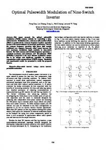
Fig. 3. Target SVM output phase a waveform, with the equivalent three-phase modulating signals and the switch sequence that results. Fig. 2. Unit vectors defined in the (stationary) d normalized v value shown in Sector I.
0 q coordinate frame, with a
sector, the two active vector components, choices of zero states, and switch sequencing are the basic tasks of SVM. In SVM, a sampling interval, , much smaller than 1/6 cycle of the intended output fundamental, is assigned. Once the vector are known, within each sampling incomponents in and terval the vector components can be considered as a time weight or duty ratio. The switches operate to apply each of the two desired active vectors for a specific fraction of . Then zero state intervals are added to make the total time come out to . This is a PWM process, in the senses that the average behavior over intervals tracks the desired output vector, and that the many time weights can be interpreted as duty ratios. In practice, the , with an vector components are re-computed at each time integer. Thus these times serve as uniform sampling intervals, and the average behavior over each interval is determined by . the voltage vector at time Fig. 3 shows an example of an SVM process in time domain, given a switching frequency that is 15 times the intended fundamental output frequency (the modulation frequency) and 95% modulation relative to a sine. The switching sequence is shown at the bottom. The equivalent distorted modulation, with the reference sinusoid for phase a, is shown at the top. In Sector I, the such that only one switch switch sequence is 0-4-6-7-6-4-0 changes state at a time. The sequences for the other sectors can be obtained from Fig. 3. In a given sector, the vector-domain form of the desired output voltage is (1) and become the time in which vector components weights associated with switch state and , respectively. The is the sampling interval. Zerototal time state durations and are arbitrary, provided their sum gives the correct , which shows that there is a degree of freedom.
In classical SVM (as in [1]), each zero state is applied for an . identical interval, to give It has been established (see eq. (20) in [1]) that a scaling factor is introduced in the space-vector definitions. The vector scale , where is the modulating in space-vector domain is associated with full depth for each phase voltage (with sinusoidal modulation). The factor of 3/4 can be derived first by noting that is determined by (2) is the peak output phase voltage. When the (balwhere anced) time-domain phase voltages are transformed to coordinates using the conventional un-normalized Park transformation [18], another factor of 3/2 appears. As a result, the scaling from phase voltages to the desired output vector becomes
(3) To relate this more effectively to time domain, the normalized voltage components can be associated with time functions and , respectively. With these definitions, the normalized output voltage vector can . The need be written as from a basis into an in SVM is to transform basis (with basis vectors ) to find and in (1). In Sector basis by I, the basis vectors are and , related to the (4) where is a 2 2 transformation matrix that is sector dependent. The transformation matrices are given in Table I for all sec-
66
IEEE POWER ELECTRONICS LETTERS, VOL. 1, NO. 3, SEPTEMBER 2003
TABLE I TRANSFORMATIONS AND BASES FOR EACH SECTOR UNDER SVM
tors. Sector I is used as the basis for the treatment here without loss of generality. The matrix relates the basis vectors. For this linear transformation, the components are related such that vector components in column form are times the components. Thus components and can the now be computed as
(5) The time argument in (5) requires sampling to support computation of the durations. At the sampling times, (5) becomes
(6) The switch sequence must also be chosen. Typically, a separate state machine tracks the sequence that minimizes the number of transitions [19]. To relate these results to double-sided UPWM, in which three-phase time domain waveforms would be used in place of vectors, we need the inverse Park transformation in the stationary reference frame
(7)
, etc., are phase modulating signals and is Here a possible zero-sequence signal. Notice that (7) is sector-independent in contrast with the transformation in (4). When a zero-sequence signal is included, there is no effect on the baseband frequency components of the output line voltage. For ex, where is a ample, we can let third-harmonic injection, without introducing baseband output line distortion. In UPWM the duty ratios for each phase, with no zero-sequence injection, are given by [12] (8)
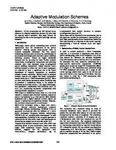
Fig. 4. Double-sided UPWM process, switching at 15 times the modulating frequency. The switch states S through S are represented on the lower trace.
where denotes phase leg a, b or c. In coordinates, the three upper switch duty ratios from (7) can be represented, given (8), as
(9) In contrast to (6), these expressions are sector-independent. They do not require tracking of the switch sequence or of the active sector. An example waveform in given in Fig. 4, based on double-sided UPWM. Notice that the switching sequence, shown again at the bottom, is identical to that of SVM. It is possible to show that the switch sequence produced by double-sided UPWM automatically involves one switch and at a time. In Sector I, the components are at all sampling times. This yields , which leads to a switch sequence in which only one device operates at any moment. Under leading-edge modulation, the state sequence becomes 7-6-4-0. Under trailing-edge modulation, it is 0-4-6-7. For double-edge modulation, the sequence 0-4-6-7-6-4-0 matches the one for SVM. The analysis can be extended for all six sectors. The patterns are consistent, but what about the times? In Sector I, UPWM yields states 4 and 6 and , respectively, which will be for time intervals
(10) These results match (6) exactly. Thus the switching sequences and active state durations match between SVM and doublesided UPWM. The total time spent in the zero states must also match.
KWASINSKI et al.: TIME DOMAIN COMPARISON OF PULSE-WIDTH MODULATION
67
A distinction is that UPWM in its most straightforward application produces in Sector I (11) compared to SVM, in which the choice of splitting the zero states is arbitrary. In sinusoidal UPWM, the zero states do not match, and in effect are timed to avoid any zero sequence . Thus, SVM is equivalent to a UPWM process in which a zero-sequence waveform has been added to constrain . While SVM is often said to “automatically” achieve an extended linear modulation range, it is analogous to say that sinusoidal UPWM “automatically” avoids zero-sequence distortion. Notice the inherent simplicity of (8) above. SVM requires reference frame to a time-dependent transformation from a frame, as well as tracking of the switch state sequence. When vector voltages are already available, the only process to be added to (8) is a static inverse Park transform from to coordinates, yielding (9). When time-domain three-phase voltages are available, the direct computation of (8) can be used instead. More generally, once it is appreciated that classical SVM produces the same result as UPWM, then other UPWM approaches can be used to compute the desired duty ratios for three-phase inverter outputs.
Fig. 5. Double-sided UPWM with third-harmonic injection (m/6). The modulation signals and the resulting switch sequence are shown.
in UPWM with less baseband distortion by adding sinusoidal zero-sequence of the form (13)
III. SAMPLING ISSUES AND NPWM Why is NPWM not used in most three-phase inverters? Aside from the difficulties associated with an analog implementation, a digital implementation of NPWM requires computation of the crossing points of the sinusoidal modulating function and the carrier [20]. The computational effort is an important limitation in real-time systems. UPWM is much more tractable. The duty ratios can be assigned immediately at each pre-defined sampling time, and it is unnecessary even to form the triangle function. In the context of switching audio amplifiers, the improved output quality of NPWM justifies the extra computation. More efficient methods for computing NPWM crossing times are in development [13], and it may soon become practical for inverter applications. It can also be shown that double-sided NPWM generates the same switch sequences and single-switch action as SVM. gives rise to a zero-sequence Classical SVM with signal equal to half the mean fundamental signal in each sector [21]. For example, (12) in sectors I and IV. With the other sectors, the total yields a waveform that is essentially a triangle at three times the funbased on (12) injects damental frequency [16]. The signal all triplen harmonics into the modulating signal [12], although only the third harmonic is needed to allow to be raised as high without overmodulation. This gives rise to the familiar as ) linear modulation range extension. 15% (which is The trouble with the extra components is that they can interact with the carrier to produce additional distortion components at the output. As in [22], the same range extension can be achieved
The distorted phase voltages for third-harmonic injection are were given in Fig. 3. The shown in Fig. 5. Those for switching sequences in Figs. 3 and 5 are the same, and only the zero-state intervals differ. As with any zero-sequence injection, the output line voltages experience no baseband distortion. The implication of the above discussion is that, in general, classical SVM is not optimal in any sense with respect to harmonics and noise. Sinusoidal UPWM with third harmonic injection gives better results, and NPWM avoids baseband distortion entirely. On the other hand, no known PWM process, including SVM, reaches the THD performance of well-known harmonic cancellation approaches [23]. IV. CONCLUSION SVM provides the same switch action and inverter output as a double-sided UPWM process with injected triplen harmonics. The switching sequences of double-sided PWM methods with a given operating frequency match those of SVM. SVM extends the linear modulation range 15% as compared with pure sine-wave UPWM, but this is achieved through injection of triplen harmonics and offers no advantages over conventional third-harmonic injection schemes. Implementations of UPWM processes are simple and direct. There is no need to track the operating sector or add a state machine for switch sequencing. Vector-based methods of SVM do not reduce the computational burden compared to time-domain UPWM. In terms of harmonics, natural sampling avoids baseband distortion. NPWM requires more computational effort than UPWM because of calculation of the crossing times. However, developments in switching audio are making the NPWM process more suitable for real-time applications. It is likely that
68
IEEE POWER ELECTRONICS LETTERS, VOL. 1, NO. 3, SEPTEMBER 2003
NPWM approaches will have impact in the near future, since digital sine-triangle pulse-width modulation offers performance advantages over space-vector approaches.
REFERENCES [1] H. W. Van der Broeck, H. C. Skudelny, and G. V. Stanke, “Analysis and realization of a pulsewidth modulator based on voltage space vectors,” IEEE Trans. Ind. Applicat., vol. 24, pp. 142–150, Jan./Feb. 1988. [2] Z. Yu, A. Mohammed, and I. Panahi, “A review of three PWM techniques,” in Proc. Amer. Control Conf., 1997, pp. 257–261. [3] V. R. Stefanovic and S. N. Vukosavic, “Space-vector PWM voltage control with optimized switching strategy,” in Proc. IEEE Industry Applications Soc. Annu. Meeting, 1992, pp. 1025–1033. [4] A. M. Massoud, S. J. Finney, and B. W. Williams, “Control techniques for multilevel voltage source inverters,” in Proc. IEEE Power Electronics Specialists Conf., 2003, pp. 171–176. [5] S. Manias, “Voltage source converters for dc grid wind farm applications,” tutorial presentation at the IEEE Power Electronics Specialists Conf., 2003. [6] J. Klima, “Analytical model for the time and frequency domain analysis of space-vector PWM inverter fed induction motor based on the Laplace transform of space-vectors,” in Proc. Power Conversion Conf., Osaka, Japan, 2002, pp. 1334–1339. [7] G. Narayanan and V. T. Ranganathan, “Extension of operation of space vector PWM strategies with low switching frequencies using different overmodulation algorithms,” IEEE Trans. Power Electron., vol. 17, pp. 788–798, Sept. 2002. [8] D. G. Holmes, “The general relationship between regular-sampled pulse-width-modulation and space vector modulation for hard switched converters,” in Proc. IEEE Industry Applications Soc. Annu. Meeting, 1992, pp. 1002–1009. [9] H. B. Ertan, M. Y. Üçtu˘g, R. Colyer, and A. Consoli, Modern Electrical Drives. Dordrecht, The Netherlands: Kluwer, 2000. [10] B. K. Bose, Modern Power Electronics and AC Drives. Englewood Cliffs, NJ: Prentice-Hall, 2002, pp. 224–236.
[11] J. T. Boys and P. G. Handley, “Harmonic analysis of space vector modulated PWM waveforms,” Proc. Inst. Elect. Eng. Elec. Power Applicat., vol. 137, no. 4, pp. 197–204, July 1990. [12] S. Bowes and Y. S. Lai, “The relationship between space-vector modulation and regular-sampled PWM,” IEEE Trans. Ind. Electron., vol. 44, pp. 670–679, Sept./Oct. 1997. [13] C. Pascual, Z. Song, P. T. Krein, D. V. Sarwate, P. Midya, and W. J. Roeckner, “High-fidelity PWM inverter for digital audio amplification: spectral analysis, real-time DSP implementation, and results,” IEEE Trans. Power Electron., vol. 18, pp. 473–485, Jan. 2003. [14] S. R. Bowes, “New sinusoidal pulsewidth-modulated invertor,” Proc. IEE, vol. 122, no. 11, pp. 1279–1285, 1975. [15] S. R. Bowes and B. M. Bird, “Novel approach to the analysis and synthesis of modulation processes in power convertors,” Proc. Inst. Elect. Eng., vol. 122, no. 5, pp. 507–513, 1975. [16] A. M. Hava, R. J. Kerkman, and T. A. Lipo, “A high-performance generalized discontinuous PWM algorithm,” IEEE Trans. Ind. Applicat., vol. 34, pp. 1059–1071, Sept./Oct. 1998. , “Carrier-based PWM-VSI overmodulation strategies: analysis, [17] comparison, and design,” IEEE Trans. Power Electron., vol. 13, pp. 674–689, July 1998. [18] R. H. Park, “Two-reaction theory of synchronous machines—generalized method of analysis,” AIEE Trans., pt. I, vol. 48, pp. 716–727, July 1929. [19] K. Zhou and D. Wang, “Relationship between space-vector modulation and three-phase carrier-based PWM: a comprehensive analysis,” IEEE Trans. Ind. Electron., vol. 49, pp. 186–196, Jan./Feb. 2002. [20] S. R. Bowes and A. Midoun, “Suboptimal switching strategies for microprocessor-controlled PWM inverter drives,” Proc. Inst. Elect. Eng. Part B, vol. 132, no. 3, pp. 133–148, 1985. [21] V. Blasko, “Analysis of a hybrid PWM based on modified space-vector and triangle-comparison methods,” IEEE Trans. Ind. Applicat., vol. 33, pp. 756–764, May/June 1997. [22] J. A. Houldsworth and D. A. Grant, “The use of harmonic distortion to increase the output voltage of a three-phase PWM inverter,” IEEE Trans. Ind. Applicat., vol. 20, pp. 1224–1228, Sept./Oct. 1984. [23] H. S. Patel and R. G. Hoft, “Generalized techniques of harmonic elimination and voltage control in thyristor inverters: part I—harmonic elimination,” IEEE Trans. Ind. Applicat., vol. IA-9, pp. 310–317, May/June 1973.