第 13 卷
太赫兹科学与电子信息学报
第 3 期
Vo1.13,
No.3 2015 年 6 月
Journal of Terahertz Science and Electronic Information Technology
Jun.,2015 文章编号:2095-4980(2015)03-0000-08
Oscillation detection technique by using Vector Network Analyzer Ata Khalid 1* ,Chong Li 1 ,Lai Bun Lok 2 ,David R S Cumming 1 (1.School of Engineering, University of Glasgow,Glasgow UK,G12 8LT;2.Department of Electronic and Electrical Engineering,University College London,London UK,WC1E 7JE)
Abstract:A Vector Network Analyzer(VNA) can be used to identify oscillation frequency of a signal source with moderate or low Radio Frequency(RF) power if certain care is taken according to experimental results. Unlike reported in the literature that a resonant peak of measured absolute value of reflection coefficient greater than 1 that corresponds to an oscillation frequency, we report that by observing the magnitude change of one -port reflection coefficient across the entire swept frequency range, a sudden peak or a dip corresponds to an oscillation frequency, this is more accurate than other reports. In addition, using modern VNA as a signal detection method can significantly reduce measurement time and increase measurement accuracy to VNA capability for developing emerging signal generating devices at early stage, especially for planar, large quantity and operating in a wide frequency range. Key words:Vector Network Analyzer;scattering parameters;oscillators;microwave and millimeter wave measurement CLC number:TN248.6
Document code:A
Received date:2014-10-23;Revised date:2014-12-31 * Corresponding
author:Ata Khalid, email:
[email protected]
doi:10.11805/TKYDA201503.0000
太赫兹科学与电子信息学报
204
第 13 卷
The VNA is a well-recognized sophisticated instrument for characterizing passive components such as waveguides, filters, combiners and active semiconductor devices such as diodes, transistors as well as circuits like oscillators and amplifiers [1-2] . By measuring scattering parameters(S-parameters) of a Device-Under-Test(DUT) and extracting testing pads or parasitic circuits, parameters such as impedance, Voltage Standing Wave Ratio(VSWR), gain or loss and group delay etc. of the actual devices can be obtained [3-4] . Such measurement can be carried out for one port or multi-port devices. Special care must be taken when using VNA to measure the reflection coefficient of one-port active devices and therefore deriving their impedances [5] , because some active devices such as Resonant Tunnelling Diodes(RTDs) [6-7] and impact ionisation and avalanche transit time(IMPATT) diodes [8] have Negative Differential Resistance(NDR) or Negative Differential Conductance(NDC) in a wide frequency range and the small-signal measurement using VNA may cause devices to oscillate. On the other hand, active devices such as transferred electron devices(or Gunn devices) generate self-sustained oscillations [9] . It is difficult to measure the impedances of such devices using VNA because they are usually embedded in a waveguide cavity that contains a disc resonator, a tuning slot, a heat sink and so on. These elements lead to difficulties in de-embedding the real parameters of Gunn devices from other circuits [10-11] . However, it is relatively easier to obtain the impedance of planar type Gunn devices when they are fabricated using MMIC methods [12-13] . Apart from deriving internal impedances of the active devices, the VNA, as wi ll be discussed in detail later, can be used to identify oscillation frequency of a signal source or an oscillator [14-15] . Traditionally, the method of measuring an oscillation frequency at microwave and millimetre wave frequency range is to use a spectrum analyzer that down-converts a Radio Frequency(RF) signal to an Intermediate Frequency(IF) signal by its internal or external mixers and using conventional analog method to calculate the frequency and amplitude information for the IF signal [3-4] . A commercial stand-alone spectrum analyzer has a limited operating frequency range which can be extended using external mixers. Once external mixers are introduced, it becomes extremely difficult to identify a real signal out of many image and inter -modulating frequencies, which is not the case when the internal mixers are used because the spectrum analyzer normally has very well-controlled circuits to suppress those spurious signals, although many efforts such as signal identification functions have been made to improve the performance by manufacturers [16-17] . In addition, modern signal source development has included many new features such as miniaturized planar structure, large quantity, moderate or low
RF power and operating in a wide frequency
bias-T
DC power supply
on-wafer probe
mixer+diplexer
range etc. that are challenging to the spectrum analyzer measurement method. Therefore an
DUT
effective and efficient measurement technique is
(a) on-wafer spectrum analyzer measurement setup
clearly required. From our experimental data
DC power supply
and theoretical analysis, it is found that the VNA can be used to identify an oscillation frequency. Moreover, the VNA has also shown many advantages, measurement,
especially over
for
spectrum
measurements as discussed below.
on-wafer analyzer
spectrum analyzer 50 GHz
DUT
on-wafer probe
frequency extender
(b) on-wafer VNA measurement setup
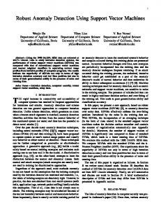
Fig.1 Typical block diagrams
VNA 67 GHz
第3期
Ata Khalid et al:Oscillation detection technique by using vector network analyzer
205
Firstly, VNA may have simpler measurement setup than spectrum analyzer. The latest VNA instrument has a single setup for frequencies from as low as 70 kHz to 110 GHz from Anritsu (ME7828A) or 10 MHz up to 110 GHz from Agilent(N5250C) and R&S (ZVA110). On the contrary, three setups are normally required for spectrum analyzer measurement setup to cover the same frequency range e.g. 3 Hz-50 GHz, 50 GHz-75 GHz and 75 GHz-110 GHz, because the spectrum analyzer measurement method is commonly band -limited due to the need for external waveguide mixers and probes. Fig.1 shows typical simplified block diagrams for on-wafer spectrum analyzer measurement setup and on-wafer VNA measurement setup. Fig.2 shows a typical W-band on-wafer spectrum analyzer measurement setup and a semi-automated DC(10 MHz)-110 GHz on-wafer VNA measurement setup. One can clearly see from both block diagram and experimental s etup that for spectrum analyzer measurement the probe and mixer should be changed for different frequency band measurement for below 110 GHz. However, this is not necessary for the VNA measurement setup. A single measurement covers up to 110 GHz. In addition, it is common that Current-Voltage(IV) and Capacitance-Voltage(CV) measurements are needed for active DUTs, the semi-automated VNA setup can make both types of measurement along with frequency measurement without changing any setups but a semiconductor device analyzer such as B1500a from Agilent. This “all-in-one” setup can dramatically reduce the time needed for characterising devices. For frequencies above 110 GHz, both the spectrum analyzer and VNA measurement methods require at least two separate setups (140 GHz-220 GHz and 220 GHz-325 GHz). Secondly, apart from having simple “all-in-one” measurement setup, VNA have another advantage over spectrum analyzer that is VNA can measure low power oscillator devices at high frequencies(>140 GHz). In that frequency range, spectrum analyzer measurement needs an external mixer which normally has very large conversion loss (e.g. >50 dB), if a signal has low RF power for example -40 dBm, it becomes difficult for the spectrum analyzer to detect the signal due to the limit of internal noise floor, dynamic range and minimum detectable power etc unless an amplifier is added immediately after the mixer. However, VNA may be capable of measuring such low level signal. The experimental results will be g iven in the following sections. power supply
mixer
VNA
spectrum analyzer
diplexer
frequency extender
frequency extender
active DUT and probe
active DUT and probe
(a) on-wafer spectrum analyzer measurement
(b) on-wafer VNA measurement
Fig.2 Experimental setups
We first present a series of experimental results using VNA to measure osci llation frequency of different signal sources that are described in Experiment section 1. Finally, some special considerations for properly using the VNA to identify oscillation frequencies are considered in sectio n 2 ''Discussion''.
206
1
太赫兹科学与电子信息学报
第 13 卷
Experiments An extensive theoretical discussion on the signal characteristics generated by the DUT and the reflected
stimulus signal can be found elsewhere [18-19] . It can be shown theoretically that in most cases the VNA can be used to identify an oscillation from the DUT by observing a sudden change(a peak or a dip) in the measured reflection coefficients of a DU T [18] . In order to verify the feasibility of using VNA to identify the oscillation frequency, experiments have been carried out two diffe rent types of DUTs such as a commercial signal generator and planar Gunn oscillators. Special considerations such as output power of the signal generated by the DUTs, the number of sampling points and the IF bandwidth have also been investigated to achieve the best performance for using VNA to identify oscillation frequencies. 1.1 Commercial signal generators A commercial signal generator (Agilent E8257D) was used to test the theory discussed in section 1 because it has well controlled output power level(-20 dBm-+15 dBm) and fine frequency resolution (0.001 Hz for continuous wave mode) [19] , which are very important in this experiment. The output port of the signal generator was connected to a 3 dB attenuator that has impedance of 50 Ω over its frequency range of operation(DC-50 GHz) to improve port matching of the signal generator. The VNA used for this experiment was Agilent E5071B with the output power of from the test port between -15 dBm and +10 dBm [18] . Firstly, an experiment with different output power from the signal genera tor was carried out and the results are plotted in Fig.3. The output power of the signal source was varied from -15 dBm to +15 dBm in steps of 6 dB. Prior to the measurement, the VNA was calibrated with power of 0 dBm between 1 GHz and 2 GHz with 801 points by using Short-Open-Load method and the calibration standards used was 85052D 3.5 mm Economy Calibration Kit from Agilent. One can see from (b) to (g) in Fig.3 that a peak appears at 1.5 GHz once the signal generator output ted a signal at 1.5 GHz compared with no peaks in Fig.3(a) where the signal generator output was not activated. In addition, the amplitude of the peaks( S 11 ) grows as the output signal power from the signal generator increases. The amplitude of the peaks corresponds to the power difference between the signal from the signal generator and the stimulus from the VNA. This can simply be written as the flowing equation
S11 PDUT PVNA
(1)
where PDUT (dBm) is the signal power level of the DUT and PVNA (dBm) is the power level of the VNA. Rearrange (1) and generalize PDUT as Preflect we can get
Preflect S11 PVNA
(2)
Which can be used to calculate the reflected power Preflect based on the measured S 11 at other frequency point where no signal is generated by the DUT. Furthermore, unlike [14-15], the amplitude of the peaks can be smaller than 0 dB to indicate a signal unless there is peak observed. In this experiment, the power level of the signal from signal generator (from -18 dBm to 12 dBm) was higher than the power level of the reflected signal (less than -20 dBm because the VNA was calibrated with power level of 0 dBm and the measured S 11 is less than 20 dB), therefore obvious peaks are expected to be observed as shown in Fig.3.
第3期
Ata Khalid et al:Oscillation detection technique by using vector network analyzer 0
0 -18 dBm
no signal -10
S-parameter S11/dB
S-parameter S11/dB
-10 -20 -30 -40 -50
-30 -40
-60 1.0
1.5 f/GHz (a)
2.0
1.0
0
1.5 f/GHz (b)
2.0
0 -12 dBm
-6 dBm
-10
S-parameter S11/dB
-10
S-parameter S11/dB
-20
-50
-60
-20 -30 -40 -50
-20 -30 -40 -50
-60 1.0
-60 1.5 f/GHz (c)
1.0
2.0
0
1.5 f/GHz (d)
2.0
10 0 dBm
6 dBm
0
S-parameter S11/dB
-10
S-parameter S11/dB
207
-20 -30 -40 -50
-10 -20 -30 -40 -50 -60
-60 1.0
1.5 f/GHz (e)
1.0
2.0
1.5 f/GHz (f)
2.0
20 12 dBm
S-parameter S11/dB
10 0 -10 -20 -30 -40 -50 -60 1.0
1.5 f/GHz (g)
2.0
Fig.3 The measured reflection coefficients of a signal source when it was not activated (a), and activated and generated a signal at 1.5 GHz with output power from -15 dBm to +15 dBm (b)-(g). The VNA was calibrated with output power of 0 dBm in the frequency range between 1 GHz and 2 GHz. The number of sampling points was 801. A 3-dB attenuator was inserted between the VNA and the signal generator.
Secondly, power level PDUT from the signal generator was fixed at a certain value, e.g. -18 dBm, -12 dBm, -6 dBm and 0 dBm, and the VNA was calibrated with different power level PVNA , e.g. -15 dBm, -9 dBm, -3 dBm, 3 dBm and 9 dBm. Similar results have been found as long as S11 was far greater than -28 dB that is the measured S11 at 1.5 GHz while the signal generator did not output any signals. Exception happened when
太赫兹科学与电子信息学报
208
第 13 卷
S11 is close to -28 dB, for instance PDUT 18 dBm and PVNA 9 dBm and S11 27 dB according to (1). In this case the phase difference between the reflected signal and the DUT generated signal plays a significant role in the total detected power at the VNA test port as shown in Fig.4. The measured S11 varies between -40 dB and -21dB. The results shown in Fig.4(a) and (b) indicate that the phase difference is within ( / 2, / 2) ; on the other hand, Fig.4(c) and (d) indicate the phase difference is within ( / 2,3 / 2) . Thus, it is necessary to use low PVNA in order to detect a low power signal, because lower PVNA increases both S11 according to (1) and this makes it more easily distinguished from reflection coefficients at neighbouring points.
1.2 Planar Gunn diodes Another type of signal source planar Gunn diodes [13,20-21] has also been tested. This is an emerging type of transferred electron devices having a truly planar structure, which is amenable for on -wafer measurements. Since the planar Gunn diode also has a coplanar test pads, unlike a conventional Gunn oscillator which will be limited by the cut-off frequency of rectangular waveguides [ 2 1 ] , there is no lower cut-off frequency for the CPW structures. This allows one to measure the frequency response of devices with changing measurement setup at any frequency range in order to identify the fundamental-mode of oscillation. A planar Gunn diode was first tested using spectrum analyzer method from 3 Hz to 110 GHz with three different setups. They include a stand -alone spectrum analyzer covering from 3 Hz to 50 GHz and a probe (DC-65 GHz), a V-band (50 GHz-75 GHz) mixer with the spectrum analyzer as well as a V-band probe, and a W-band probe, W-band mixer and the spectrum analyzer. The same device was also tested by VNA (10 MHz-110 GHz) and both results are shown in Fig.5 for comparisons. 0
0 -39.7 dBm at 1.5 GHz
-10
S-parameter S11/dB
S-parameter S11/dB
-5
-15 -20 -25 -30
-10 -15 -20 -25 -30
-35
-35
-40
-40
-45 1.0
-45 1.5 f/GHz (a)
1.0
2.0
1.5 f/GHz (b)
2.0
0
0 -24.3 dBm at 1.5 GHz
-5
-5
-10
S-parameter S11/dB
S-parameter S11/dB
-32.7 dBm at 1.5 GHz
-5
-15 -20 -25 -30
-15 -20 -25 -30
-35
-35
-40
-40
-45
-45 1.0 1.0
1.5 f/GHz (c)
2.0
-21.5 dBm at 1.5 GHz
-10
1.5 f/GHz (d)
2.0
Fig.4 Measured reflection coefficients of the signal source with output power of -18 dBm. The VNA was calibrated with output power of 9 dBm
第3期
Ata Khalid et al:Oscillation detection technique by using vector network analyzer
209
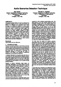
One can see that the results from both measurement methods show same oscillation at 106 GHz in Fig.5. Apart from this, the VNA measurement results show anothe r piece of important information that the 106 GHz signal is the fundamental oscillation frequency of this DUT, because the si ngle sweep shows only one peak at 106 GHz and no peaks or dips are seen at any other frequency range. This was validated using three different setups based on the spectrum analyzer. The same results are obtained. No oscillation tones below 106 GHz were observed. To identify the fundamental oscillation frequency of an emerging source is extremely important, because this will establish the advantages of the new technology. Importantly the VNA method has one single setup and one single sweep that measures what three setups of spectrum analyzer measurement 0 106 GHz
power/dBm
-10 -15 -20 -25 -30 -35 105.6
105.8
106.0
106.2 f/GHz (a) power
16 14 12 10 8 6 4 2 0 -2
reflection coefficient |S11|/dB
-5
106.4
106.6
106.8
106 GHz
VNA |S11|/dB |S11|=0 dB
0
10
20
30
40
50 60 70 80 f/GHz (b) reflection coefficient
90
100 110
Fig.5 A planar Gunn diode was tested by using spectrum analyzer method and VNA method. The spectrum analyzer method used a spectrum analyzer, a diplexer, a W-band mixer and a W-band probe. The VNA has 401 sampling points between 10 MHz and 110 GHz.
can do. This is one of the main advantages of using a VNA over a spectrum analyzer for detecting millimetre-wave oscillation frequencies. 1.3 Low power high frequency active devices At high frequency range, the common spectrum analyzer and external mixer setup has difficulties to detect low power signals due to the high conversion loss of the mixer. In some cases the conversion loss is greater than 50 dB at frequencies above 100 GHz. Therefore low noise amplifiers are usually attached to the mixers for improving their performance. However, it is still very challenging when amplifiers are not included. An
experiment
was
carried
out
at
high 15
diode which had a fundamental oscillation at 92 GHz that has been confirmed by using both spectrum analyzer method and VNA method. As most Gunn diodes exhibit non-sinusoidal oscillation, it means higher harmonic oscillations exist. Therefore we expect to see the second harmonic oscillation of this device at near 184 GHz by using spectrum analyzer measurement method. However, due to the high
reflection coefficient |S11|/dB
frequency(>100 GHz). The DUT was a planar Gunn
92 GHz
10 5 0 183 GHz
-5 -10 -15 0
20
40
60
80
100 120 f/GHz
140
160
180
200 220
Fig.6 Another planar Gunn diode was tested by using VNA method (10 MHz-110 GHz and 140 GHz-220 GHz).
conversion loss of the mixer, we were not able to see any oscillation on the spectrum analyzer. On the contrary, the second harmonic oscillation at 183 GHz was detected by the VNA system as shown in the Fig.6. The results show a fundamental oscillation at 92 GHz and its second harmonic at 183 GHz . The fundamental oscillation frequency was detected by spectrum analyzer method. But the second harmonic oscillation was not detected due to the high conversion loss of the G-band mixer used. The number of sampling points was set to be 401 for both frequency ranges.
210
太赫兹科学与电子信息学报
第 13 卷
The slight frequency drift comes from the bias voltage differen ce for the two VNA systems (10 MHz-110 GHz and 140 GHz-220 GHz) used. This result shows that VNA has great potential as a future high frequency low power measurement methodology compared to conventional spectrum analyzer measurement setups.
2
Discussion It has been experimentally demonstrated that a VNA can be used to identify oscillation frequencies of
one-port active devices by observing the changes in reflection coefficient. Still there are some special considerations in order to use this techniq ue effectively and correctly. 2.1 Sampling points and phase noise of the signal The characteristics of the signal generated by DUTs determine the number of sampling points needed in the sweep for VNA measurement. If the signal has a high phase noise, it shows a wide bandwidth in frequency domain. This means that a lower number of sampling points are needed within the frequency band for test. On the other hand, if a signal has a relatively “clean” spectrum, a large number of sampling points are required in order not to omit any frequency components. However the setup of IF bandwidth may compensate as will be discussed in 2.3. 2.2 Power level of active DUTs It has been found, it is desirable that the sum of output power from DUTs and the stimulus does not exceed the input power limit of the VNA test ports (e.g. +30 dBm for VNA N5020C). Otherwise, phase lock will be lost or, in the worst case, the test ports can be damaged. 2.3 IF bandwidth The bandwidth of IF filter determines accuracy of measurement results and speed of measurement. The wider the IF bandwidth, the faster the VNA can sweep and the poorer the accuracy. It is desirable to set the IF bandwidth to a smaller value e.g. 50 Hz in VNA’s regular application, such as S-parameter measurement on passive devices, because the narrow IF bandwidth leads to accurate measurement. However, in application of identifying oscillation frequencies the IF bandwidth of VNA is recommended to be larger e.g. 50 kHz. This is because firstly large IF bandwidth makes the measurement faster; secondly, the large IF bandwidth ensures the signal generated by the DUT is within the two sampling points. This reduces the possibility of omitting the DUT generated signal ; and finally, large IF bandwidth leads to more accurate power level measurement. Finally based on our experimental results, we anticipate that future VNA would include an option to detect signals from the DUT and replace the requirement of a spectrum analyser as a separate tool.
3
Conclusion In conclusion, VNA application has been investigated to experimentally prove this instrument as an effective
and efficient tool to accurately identify the oscillation frequency of one-port RF signal sources by observing a sudden change of magnitude of reflection coefficient. This techniqu e will benefit modern signal source development, which has many new features such as miniaturized planar structure, large quantity, moderate or
第3期
Ata Khalid et al:Oscillation detection technique by using vector network analyzer
211
low RF power and operating in a wide frequency range etc.
References: [1]
David M Pozar. Microwave Engineering[M]. 2nd ed. Toronto:John Wiley & Sons, 1998.
[2]
Vendelin G D,Pavio A M,Rohde U L. Microwave Circuit Design Using Linear And Nonlinear Techniques[M]. 2nd ed. Hoboken,New Jersey:John Wiley & Sons, 2005.
[3]
Witte R A. Spectrum and Network Measurements[M]. Raleigh:Scitech, 2006.
[4]
Collier R J,Skinner A D. Microwave Measurements[M]. 3rd ed. London:The Institution of Engineering and Technology, 2007.
[5]
Grace M I. Negative-resistance device measurements[J]. Microwave Journal, 1998,41(3):126-135.
[6]
Cohen G M,Ritter D. Microwave performance of Ga x In 1-x P/Ga 0.47 In 0.53 As resonant tunneling diodes[J]. IET Electronics Letters, 1998,34(12):1267–1268.
[ 7 ]. Mounaix P,Bedu P,Lippens D. Measurement of negative differential conductance to 40 GHz for vertically integrated resonant tunnelling diodes[J]. IET Electronics Letters, 1991,27(15):1358–1360. [ 8 ]. Hasch J,Kasper E. S -parameter characterization of mm-wave IMPATT oscillators[C]// 2006 topical meeting on silicon monolithic integrated circuits in RF systems. San Diego,CA,USA:IEEE, 2006. [9]
Gunn J B. Microwave oscillation of current in Ⅲ - Ⅴ semiconductors[J]. Solid State Communications, 1963,1(4):88-91.
[10]
Khandelwal D D,Curtice W R. A study of the single-frequency quenched-domain mode Gunn-effect oscillator[J]. IEEE Transactions on Microwave Theory and Techniques, 1970,18(4):178-187.
[11]
Kawashima M,Hartnagel H. New measurement method of Gunn-diode impedance[J]. IET Electronics Letters, 1972,8(12): 305–306.
[12]
Förster A,Lepsa M I,Freundt D,et al. Hot electron injector Gunn diode for advanced driver assistance systems[J]. Applied Physics A, 2007,87(3):545-558(14).
[13]
LI C,Khalid A,Pilgrim N,et al. Novel planar Gunn diode operating in fundamental mode up to 158 GHz[J]. Journal of Physics Conference, 2009.
[14]
CHEN Y K,Radulescu D C,WANG G W,et al. Observation of high-frequency high-field instability in GaAs/InGaAs/ AlGaAs DH-MODFETs at K band[J]. Electron Device Letters IEEE, 1988,9(1):1-3.
[15]
Stapleton S P,Deen M J,Berolo E,et al. Experimental study of microwave reflection gain of AlAs/GaAs/AlAs quantum well structures[J]. Electronics Letters, 1990,26(2):84-85.
[16]
Hunter M T,Kourtellis A G,Ziomek C D,et al. Fundamentals of modern spectral analysis[J]. IEEE Instrumentation & Measurement Magazine, 2010,14(4):12-16.
[17]
Agilent. Agilent Spectrum Analysis Basics,Application Note 150[R]. [S.l.]:Agilent Technologies, 2000.
[18]
Agilent. Agilent E5071B ENA Series RF Network Analzyers User's Guide[R]. [S.l.]:Agilent Technologies, 2007.
[19]
Agilent. Agilent E8257D PSG Microwave Analogue Signal Generator Data Sheet [R]. [S.l.]:Agilent Technologies, 2010.
[20]
Khalid A,Pilgrim N J,Dunn G M,et al. A planar Gunn diode operating above 100 GHz[J]. Electron Device Letters IEEE, 2007,28(10):849-851.
[21]
Eddison I G,Brookbanks D M. Operating modes of millimeter wave transferred electron oscillators[J]. Electronics Letters, 1981,17(3):112-113.