Output Filter Design for a Grid-interconnected Three-phase Inverter. Timothy CY Wang, Zhihong Ye, Gautam Sinha, Xiaoming Yuan. GE Global Research Center.
Output Filter Design for a Grid-interconnected Three-phase Inverter Timothy CY Wang, Zhihong Ye, Gautam Sinha, Xiaoming Yuan GE Global Research Center One Research Circle Niskayuna, NY 12309, USA Abstract - Traditionally, LC filter is used for an inverter power supply. A grid-interconnected inverter, however, has some unique requirements that an LC filter may not be sufficient. This paper comprehensively discusses the design considerations of the output filter for the grid-interconnected inverter. Different passive damping fdter solutions are compared and the optimized design guidelines are also proposed. Simulation results are provided to validate the design.
I. INTRODUCTION Traditionally, LC filter is used for an inverter power supply. A grid-interconnected inverter used in distributed generation (DG), however, has some unique requirements that an LC filter may not be sufficient. This paper comprehensively discusses the design considerations of the output filter for the grid-interconnected inverter. The design is validated by Saber simulations. A PWM converter with higher switching frequency will result in smaller LC filter size. However, switching fiequency is generally limited in high power applications. As an alternative solution, LCL filter is more attractive [1]-[3] for
i Attenuation requirement from IEEE 519 The first design consideration for the LCL filter is to meet IEEE Std. 519 requirements. Due to PWM switching, the inverter will inject ripple current into the grid. The switching frequency of the inverter is 5 mZat the given power level (175kW) and the devices (IGBTs) used. Since the gridinterconnected inverter is power generation equipment, it is
two reasons: First, it has better attenuation than LC filter given the similar size. Second, LCL filter provides inductive output at the grid interconnection point to prevent inrush current compared to LC filter. Similar to LC filter, one consideration of the filter design is damping. Active damping is generally more attractive than passive damping. However, the control bandwidth is quite limited in high power converters due to their low switching fiequency. In most cases, passive damping is considered [4]171. In this paper, the output filter design, including LCL filter design procedure and the damping filter design will be discussed systematically. 11. LCLFILTER DESIGN
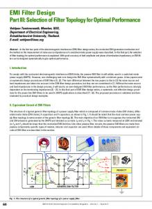
The system diagram is shown in Fig. 1. The filter has three unknowns, L1, C and L2. In the following, three considerations that lead to three equations for determining the
subject to 0.3% current limit, as fiamed in Table I. That is, the current ripple at 5 kHz should be less than 0.3% of the rated current. vbr due The current is caused by the pulsed to the inverter 'WM. During the switching On and Off, Vbr varies from to vdc (Or - vdc l2 to + vdc /2, depending On reference point). The transfer function from V b r to iL27 is shown in(1)* 1 4 2 (1) L,(L2 + L,)Cs3 + R,CL.,s2 + (L, + L, + L,)s + R, AVbr
This work was supported by US Department of Energy (DOE) under award number DE-FC02-00CHI1063.
0-7803-7754-0/03/$17.00 02003 IEEE
779
Generally, the grid impedance L, and & are varying, depending on the grid location where the inverter is connected. For a typical grid location with 500 kVA transformer, the impedance is 5.55%-6.5% with X,iRg=7-10. 8
(3) Base on Equations (1)-(3), L1, L2 and C can be determined. Take a system with 175 kW as an example, the parameters of LCL filter can be determined L 1 4 5 0 uH (12.9% impedance); C=270 uF; L2=300 uH (8.4% impedance).
iL1 ripple current requirement
The selection of the ripple current is a trade-off among inductor L1 size, IGBT switching and conduction losses, and inductor coil and core losses. The smaller the ripple current, the lower the IGBT switching and conduction losses, but the larger the inductor, resulting in larger coil and core losses. Typically, the ripple current can be chosen as 15%-25% of rated current. For this case, the ripple current is selected as 20% of the rated current. The maximum current ripple can be derived as in (2) [8]:
111. PASSIVE DAMPING FILTER DESIGN
II
I
,
I
I
I
I
1-U
I
I
I
I
I
I
TABLE I CURRENT DISTORTION LIMITS FOR GENERAL DISTRIBUTION SYSTEMS
(120V through 69 kV)
*
P "
ktsdmun, HatmodieCurrent Dlskmklon in P e m t ofTL Individual MannoniE Order (Odd H s r m i c s )
I 8
Reactivep o wer of the capacitor C 4001
The selection of the capacitor is a trade-off between reactive power in C and L1 inductance. The more capacitance, the more reactive power flowing into the capacitor, and the more current demand from the L1 and the switches. As a result, the efficiency will be lower. The capacitance cannot be too small either. Otherwise, the inductance will be large in order to meet the attenuation requirements. The larger inductance L1 resulted from smaller capacitance leads to higher voltage drop across the inductor LI. In this design, the reactive power is chosen as 15% of the rated power.
$00
ma
1 1
I I I I
I
iw8
0.31
1
I I I
I I I I I
I I
I I
1 1 I
I I I
o k
IDL
io.ok
lom
fiw
(b) Bode figure of k / V g Fig. 2. LCL filter without any passive damping.
B. Alternatives of passive damping solutions Here, several passive damping filter topologies are compared. The criteria for the following comparison are effective resonance suppression without deteriorating the attenuation at switching frequency. The Bode plots are used to analyze the performance of damping filters. The bode plots are not shown in the digest, and will be included in the full paper.
780
.
Solution 1 Fig. 3 shows one of the alternatives. The Bode figures of output current vs. both voltage sources are shown in Fig.4. It is observed that, larger Rfgives more effective damping, however, larger resistance tends to reduce the attenuation above the resonant frequency. It is undesirable from the harmonic filtering point of view. Another disadvantage is the loss due to resistor Rf at low frequency.
6
Fig. 5. Schematic of passive damping solution 2 (per phase).
““11
I
,
,
I
dB(J : 1 ( 1 1
,
I
1 P .
I
6
Fig. 3. Schematic of passive damping solution 1 (per phase).
20.0
f 10Q
300
IWQ
03k
IIk
IQh
-- -
o.o---
10.01
IO.*
Val
4OQ--
-
Bode figurc.of iLJ/Vb, I
I
I
I
I
I
I
I
1U . 40.0 10.0
30.0
1 1
I I
I 1
I
1
1
I I
I
1
1
1
I
I
I
I
I
I
1OOQ
0.3h
1Qh
).Oh
10Ih
300h
fIW
-1-
(0.0
100
4000
03k
1.Oh
3Qh
:-I
IO.Oh
--
M.Ok
qmi
.
.
(b) Bode figure of iL2/Vg Fig. 6. LCL filter with passive damping solution 2.
Solution 3 The third damping solution is shown in Fig. 7. The tuned L& circuit provides a sink at the resonant frequency. Theoretically, It is quite effective approach as shown in Fig. 8. But in reality the resonant frequency will shift with the variable grid impedance. Therefore, the damping effect is hard to be guaranteed.
(b) Bode figure of iL2/Vg Fig. 4. LCL filter with passive damping solution 1.
Solution 2 Another damping filter is shown in Fig. 5. At low frequency, the inductor Lf provides low impedance, which will reduce the resistive loss. Since Rfis the dominant current flowing path at high frequency, the harmonics attenuation is also impacted as shown in Fig. 6.
Fig. 7. Schematic of passive damping solution 3 (per phase).
781
,
M.0
I I
I
,
I
1
I
1
I
I
I
I I
1 1
1 I
-
1.Ok
3.Qk
1O.Ok
l.Ok
1OQk
10.0L
1-11
0.0
i
B
do0
1100.0
10.0
30.0
1OOQ
0.1k
fiw
(a) Bode figure of i d V b
U
404
201
609
lo00
Olt
Olk
ldk
Wk
Sot
10.01
II
I
I
1
10.0
MO
1W1
Dlk
I
1
4OL
1.0.
fW
(b) Bode figure of iL2Ng Fig. 8. LCL filter with passive damping solution 3.
mq
Solution4
The next solution is shown in Fig. 9 ['I. This solution gives as same attenuation as that without damping filter. The Bode figures are shown in Fig. 10. Larger C$C and Rf will give better damping effect, meanwhile harmonics attenuation will be reduced similarly with solution 1. The resistive loss, also tends to increase under large C$C.
.
(b) Bode figure of iLZNg Fig. 10. LCL filter with passive damping solution 3.
Solution 5 In order to reduce the resistive loss, solution 3 can be modified, which is shown in Fig. 11. Larger Rf gives more damping. Meanwhile the additional inductor Lf can reduce the resistive loss at fimdamental frequency. This is the preferred solution for DG application addressed in this paper. The corresponding Bode figures are shown in Fig. 12.
L
Fig. 9. Schematic of passive damping solution 4 (per phase).
6
- -
Fig. I I . Schematic of passive damping solution 5 (per phase).
782
damping resistors (Rf=0.68, 0.5). The resonant frequency is lower with weak grid (larger grid impedance) than stiff grid (lower grid impedance). I
I
I
I
1
ds(-) : w)
,I
3-0
...
111
...
.
... .........
CU I-U
Fig. 13. Simulated transfer functions from the input voltage to the output current. (The ones with high peak are without harmonic damping filter).
IV. SIMULATION The three-phase grid-interconnected inverter with above designed output filter has been built in SaberTM. The simulated results are shown in Fig. 14. The upper traces are grid voltage with 2% 11* harmonics and 2% 13* harmonics. The lower traces are three-phase output currents. It is shown that there is no resonance in output currents. (b) Bode figure of inng Fig. 12. LCL filter with passive damping solution 5.
400.0
200.0
C. The design guideline of damping Jilter Considering the variation of the grid impedance with 500 kVA power rating, the resonant fiequency of the LCL filter is 665Hz-703&, or around 1lth harmonic. Therefore, the harmonic filter is chosen to damp 1 lthand above. First of all, the sum of C and Cf should be kept at 2 7 0 s as designed above in order to have the same high-frequency attenuation of the overall filter. The selection of Lf and Cf is a trade-off between losses and attenuation. The larger the Cf, the less attenuation of the overall filter. The smaller Cf, however, will result in larger inductor in order to have the same 11" resonant frequency. The larger inductor will cause larger size and more inductor losses. In this design, Cf is chosen as 120uF. Then, C is 15ouF.
1 L =484~H - (27T 11* fiJ2 Cf e
(4)
0.0
-200.0
40.0
1000.0
0.11
0.16
0.17
0.26
0.13
0 .I
Fig. 14. Simulation results with Saber.
11. CONCLUSIONS
e
The damping resistor is typically chosen between 0.5-1. Fig. 13 shows the simulation results of the transfer functions of iL2Nbr without damping (three peaks) and with different
783
In this paper, the design guideline for the LCL filter used in grid-interconnected inverter has been systematically addressed. Several passive damping filters as part of the overall output filter have been discussed.
The methodology used in this paper can apply to such distributed generation applications as microturbine, fuel cell, wind power, etc.
REFERENCE [l] S . Abu-Sharkh, J. Sykuski, etc., “Current control of three-phase PWM inverters for embedded generators”, in proc. Intemational conf: On Power Electronics and Variable Speed Drives, pp. 524-529,2000, [2] M. Lindgren, “Feed forward - time efficient control of a voltage source converter connected to the grid by low pass filters”, in proc. IEEEPESC ’1995,pp. 1028 -1032. [3] M. Lindgren, “Control of a voltage-source converter connected to the grid through an LCL filter - application to active filtering”, in proc. IEEE-PESC’1998,pp. 229 -235.
[41 M. Bojrup, P. Karlsson, etc., “A multiple rotating controller for active filters”, in proc. EPE ’99. [51 J. Phipps, “A transfer function approach to harmonic filter design”, IEEE Industry Applications Magazines, Vol. 3, No. 2. March/April, 1997, pp. 68-82. A. Guru, J. Balda, etc., “Design of a switching-ripple filter for a shuntconnected active power filter”, inproc IEEE IAS’1998, pp. 1364-1368. S . Bhattacharya, D. M. Divan, etc., “Active filter system implementation”, IEEE Indus@ Application Magazine, Vol. 4, No. 5, Spetember/October, 1998, pp. 47-63. Prasad, V H, “Analysis and comparison of space vector modulation schemes for three-leg and four-leg voltage source inverters”, Master dissertation, 1997, Virginia Polytechnic Institute and State University, Blacksburg, VA.
784