Sebastian Braun1, Daniel P. Jarrett2, Johannes Fischer1, and Emanuël A.P. Habets1. 1International Audio Laboratories Erlangenâ, Am Wolfsmantel 33, 91058 ...
AN INFORMED SPATIAL FILTER FOR DEREVERBERATION IN THE SPHERICAL HARMONIC DOMAIN Sebastian Braun1, Daniel P. Jarrett2 , Johannes Fischer1, and Emanu¨el A.P. Habets1 1
International Audio Laboratories Erlangen∗ , Am Wolfsmantel 33, 91058 Erlangen, Germany 2 Dept. of Electrical & Electronic Engineering, Imperial College London, United Kingdom ABSTRACT
In speech communication systems the received microphone signals are commonly degraded by reverberation and ambient noise that can decrease the fidelity and intelligibility of a desired speaker. Reverberation can be modeled as non-stationary diffuse sound which is not directly observable. In this work, we derive a multichannel Wiener filter in the spherical harmonic domain to reduce both reverberation and noise. The filter depends on the direction-of-arrival of the direct sound of the desired speaker and an interference power spectral density matrix for which an estimator is developed. The resulting informed spatial filter incorporates instantaneous information about the diffuseness of the sound field into the design of the filter. In addition, it is shown how the proposed filter relates to the well-known robust minimum variance distortionless response filter that is also used for comparison in the evaluation. Experimental results show that the proposed spatial filter provides a tradeoff between noise reduction and dereverberation depending on the diffuse sound PSD. Index Terms— Dereverberation, spherical microphone arrays 1. INTRODUCTION In speech communication systems the received microphone signals are commonly degraded by reverberation and ambient noise that can decrease the fidelity and intelligibility of a desired speaker. Both single- and multi-microphone techniques have been proposed to reduce noise and reverberation (see [1, 2] and the references therein). While the noise can be observed during periods in which the desired speakers are inactive, the reverberation is not directly observable. In addition, the reverberation is highly time-varying while the noise can often be assumed to be time-invariant or slowly time-varying. A common solution for dereverberation is spatial filtering, where the advantages of spatial characteristics of the sound field are exploited by distributing several microphones within a room. Existing spatial filters can be broadly divided into signal-independent and signal-dependent filters. It is known that there is a tradeoff between achieving maximum directivity (and hence dereverberation) and maximum white noise gain. In [3], it was also shown that there exists a tradeoff between noise reduction and dereverberation when employing a minimum variance distortionless response (MVDR) filter and a single-channel equalization filter. In [4], a signalindependent spatial filter followed by a single-channel Wiener filter was used to reduce diffuse noise. Spatial filtering in the spherical harmonic domain (SHD) has received a lot of attention [5–12]. For a detailed introduction to the SHD, the interested reader is referred to [11–15]. In [16], the authors ∗ A joint institution of the University Erlangen-Nuremberg and Fraunhofer IIS, Germany.
978-1-4799-0356-6/13/$31.00 ©2013 IEEE
669
specifically focus on joint noise reduction and dereverberation in the SHD and require information about the directions of arrivals (DOAs) of the individual reflections which might be difficult to obtain blindly in practice. In the end, a linearly constrained minimum variance filter with spatial nulls in the direction of the reflections is used to reduce reverberation. In this work, we assume that the received signal consists of a direct sound, diffuse sound (that models the reverberant sound) and noise. As in earlier works, we assume that the direct sound and diffuse sound are uncorrelated. We derive an optimal spatial filter in the spherical harmonic domain that minimizes the mean squared error between the direct sound signal and the estimated direct sound signal, thereby reducing both reverberation and noise. The resulting multichannel Wiener filter (MWF) depends on the DOA of the direct sound from the desired speaker and the interference power spectral density (PSD) matrix. The interference PSD matrix consists of the diffuse sound and noise PSD matrices. In the SHD, the diffuse sound PSD matrix can be modeled by an identity matrix that is scaled by the PSD of the diffuse component of the zero-order eigenbeam. Here, we develop an estimator for the diffuse sound PSD based on an almost instantaneous estimate of the diffuseness. The resulting informed spatial filter incorporates instantaneous information about the diffuseness of the sound field into the design of the filter. The obtained MWF can be written in terms of an MVDR filter and a single-channel Wiener filter, and is related to the well-known robust MVDR filter [17] that is also used for comparison in the evaluation. The paper is organized as follows. In Section 2, the problem is formulated. In Section 3, the proposed informed spatial filter is derived and an estimator for the diffuse sound PSD is developed. In Section 4, it is shown how the proposed spatial filter is related to the robust MVDR filter. In Section 5, the proposed spatial filter is evaluated and its performance is compared to the robust MVDR filter. Conclusions and directions for future research are given in Section 6. 2. PROBLEM FORMULATION 2.1. Signal model To derive a spatial filter for dereverberation, we consider a signal model in which the received signal consists of a mixture of a direct sound X, a diffuse sound D and noise V . The sound field is captured by a spherical microphone array. The signal model can be expressed in the short-time Fourier transform (STFT) and SHD as1 Plm (k) = Xlm (k) + Dlm (k) + Vlm (k), (1) where k denotes the discrete frequency index, Plm (k) denotes the received signal (eigenbeam) of order l and degree m in the SHD, 1 For
brevity the time index t is omitted when possible.
ICASSP 2013
and Xlm (k), Dlm (k) and Vlm (k) denote the direct sound, diffuse sound and noise components of the eigenbeam Plm (k). The three components are assumed to be mutually uncorrelated. The eigenbeams in (1) depend on the mode strength Bl (k), which is a function of the array properties (radius, configuration and microphone type) [18]. To cancel this dependence, the eigenbeams are divided by the mode strength to yield mode strength compensated eigenbeams: h√ i−1 Pelm (k) = Plm (k) 4πBl (k) elm (k) + D e lm (k) + Velm (k). =X
(2)
2.2. Spatial filtering in the SHD Our objective is to derive a spatial filter that provides an estimate e00 (k). The desired signal X e00 (k) is of the zero-order eigenbeam X equal to the direct signal received by an omnidirectional microphone located at the center of the sphere (in the absence of the sphere). Let us consider all eigenbeam orders l and degrees m up to order L. For convenience, we write (2) in vector notation: e e (k) = x e (k) + d(k) e (k) p +v (3) where
h iT e (k) = Pe00 (k) Pe1(−1) (k) Pe10 (k) Pe11 (k) · · · PeLL (k) p
(4)
e e (k), d(k) is a vector of length N = (L + 1)2 . The vectors x and e (k) are defined in a similar manner. v e (k) can also be expressed in terms of The direct signal vector x e00 (k) and the relative transfer function the zero-order eigenbeam X from the zero-order to all other orders and degrees as e00 (k) e(k) = γ(k)X x (5)
with
e (k) x y(Ωdir ) = γ dir , (6) = ∗ e00 (k) Y00 (Ωdir ) X where y(Ωdir ) denotes a vector similar to (4), containing the com∗ plex conjugated spherical harmonics Ylm (Ωdir ), and Ωdir denotes the DOA of the direct sound. To obtain the last two terms in (6), we assume that the direct sound can be modeled as a plane wave. e (k) that consists of the We define an interference signal vector u the diffuse signal and noise signal vectors: e e (k) = d(k) e (k). u +v γ(k) =
e e(k), d(k) e (k) are assumed to be Because the signal vectors x and v e (k) is given by mutually uncorrelated, the PSD matrix of p o n e (k) p e H(k) Φpe (k) = E p = Φxe (k) + Φde (k) + Φve (k)
= φXe 00(k) γ dir γ H e (k), dir + Φu
(7)
where E {·} denotes the expectation operator, φXe 00(k) denotes the PSD of the desired signal, and Φxe (k), Φde (k), Φve (k) and Φue (k) are the PSD matrices of the desired, diffuse, noise and interference signal vectors, respectively. The output of our spatial filter is obtained by applying a complex weight to each eigenbeam, and summing over all eigenbeams: h i e e (k) = hH (k) x e(k) + d(k) e (k) Z(k) = hH(k) p +v h i e00 (k) γ + u e (k) . = hH (k) X (8) dir
e00 (k). In the next section, we derive an optimal estimator for X
670
3. PROPOSED INFORMED SPATIAL FILTER 3.1. Minimization of the diffuse plus noise output PSD e00 (k) is given The mean-squared error (MSE) between Z(k) and X by � 2 � e00 (k) J(h) = E Z(k) − X � 2 � h i e00 (k) + u e00 (k) . (9) e (k) − X = E hH (k) γ dir X
Minimizing the MSE with respect to h(k) results in the well-known multichannel Wiener filter: φXe00(k) Φ−1 e (k) γ dir u hMWF (k) = . (10) −1 φXe 00(k) γ H Φ dir e (k) γ dir + 1 u From a practical point of view, it is desirable to divide (10) into an MVDR filter and a single-channel Wiener filter (WF): φXe f(k) Φ−1(k) γ hMWF (k) = H ue −1 dir · , (11) γ dir Φue (k) γ dir φXe f(k) + φUer(k) {z } | | {z } hMVDR (k)
HWF (k)
where
φXe f(k) = hH (12) e (k) − Φu e (k)] hMVDR (k) MVDR (k) [Φp denotes the PSD of the (undistorted) direct sound signal at the output of the MVDR filter and h i−1 −1 φUer(k) = γ H dir Φu e (k) γ dir
= hH (13) e (k) hMVDR (k) MVDR (k) Φu denotes the residual interference PSD at the output of the MVDR filter. Note that the MVDR filter employed here depends on the diffuse sound and noise, while the MVDR filter in [4] is signal-independent as it depends only on the coherence matrix of the diffuse noise field. 3.2. Estimation of the diffuse PSD matrix In this section, we focus on the estimation of the diffuse PSD matrix Φde (k). While the noise PSD matrix can be assumed to change slowly over time and can be estimated during periods where the direct and diffuse sound are inactive, the diffuse PSD matrix that models the reverberation changes rapidly across time and frequency and needs to be estimated continuously. The diffuse PSD matrix can be written in terms of the PSD of the diffuse component of the zero-order eigenbeam, φDe 00(k), and the diffuse coherence matrix Γdiff (k): (14) Φde (k) = φDe 00(k) Γdiff (k). In an ideal spherically isotropic diffuse sound field, the coherence matrix Γdiff (k) is (after mode strength compensation) equal to an identity matrix [7]. For the estimation of the diffuse PSD, we propose to make use of the signal-to-diffuse ratio (SDR), which is defined here in terms of the PSD of the direct and diffuse components of the zero-order eigenbeam as in [19]: φXe 00(k) SDR(k) = . (15) φD e 00(k) Using (15), we can express the zero-order diffuse sound PSD as φXe 00(k) + φDe 00(k) φPe00(k) − φVe00(k) φDe 00(k) = = , (16) SDR(k) + 1 SDR(k) + 1
Q
STFT
SHT
...
...
Ωdir N
HWF
hMVDR
STFT-1
φUer diffuseness estimation
residual interf. PSD
diffuse PSD estimation
φD e 00
Φ−1 e (k) γ dir v . (20) −1 γH Φ dir e (k) γ dir v When δ(k) approaches infinity for all k, the robust MVDR filter reduces to the MVDR filter in (11) with Φve (k) = 0N×N : γ (21) hR (k, ∞) = lim hR (k, δ) = H dir , δ→∞ γ dir γ dir which is equal to the SHD equivalent of the well-known delay-andsum beamformer (DSB) and in the SHD achieves maximum directivity [6, 11]. The spatial filters in (21) and (20) do not require knowledge of the diffuse sound PSD φD e 00(k) and are used for comparison in Section 5. hR (k, 0) =
Φue
Ψ
bust MVDR filter is equal to the proposed MVDR filter in (11), i.e. hR (φDe 00) = hMVDR . It should be noted that the diffuse sound PSD is time and frequency dependent while the regularization parameter is usually assumed to be time and frequency independent. When δ(k) = 0 for all k, the robust MVDR filter reduces to the MVDR filter in (11) with Φde (k) = 0N×N :
φD e 00 I + Φv e
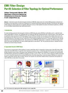
Fig. 1. Block diagram of the proposed informed spatial filter in the spherical harmonic domain. where the relation φPe00(k) = φXe00(k) + φD e 00(k) + φV e00(k) allows us to express the numerator as a function of the PSDs of the observed eigenbeams and the noise eigenbeams. In this work, we use the coefficient of variation (CV) method proposed in [20], and presented in the SHD in [19], to estimate the SDR. This estimator yields sufficiently accurate results when the noise PSD matrix is a diagonal matrix (i.e., in the absence of coherent noise sources) and the signal-to-noise ratio (SNR) is above approximately 5-10 dB. In the presence of sensor noise, the estimator can underestimate the SDR which results in an overestimation of the diffuse sound PSD. The CV method is based on the sound intensity vector and exploits the fact that a coherent sound source, which is assumed to be spatially stationary, has a time-invariant sound intensity vector, whereas a diffuse sound field exhibits a time-varying sound intensity vector. In the noise-free case, the diffuseness, denoted by Ψ(k) with 0 ≤ Ψ(k) ≤ 1, is related to the SDR by [21] SDR(k) = Ψ−1 (k) − 1. (17) Hence, we can estimate the PSD of the diffuse component of the zero-order eigenbeam using (17) and (16). Finally, the interference PSD matrix is given by Φue (k) = Φde (k) + Φve (k) = φD (18) e 00(k) I + Φv e (k), where I is the identity matrix. An overview of the spatial filtering process is depicted in Fig. 1. The Q microphone signals are transformed sequentially to the STFT domain and to the SHD. The diffuse PSD can then be calculated using (17) and (15) based on the estimated diffuseness Ψ(k) obtained using the CV method. The interference PSD matrix is computed using (18) and finally, the spatial filter can be computed using (11). A major advantage of using the form in (11) is that it provides better control over the single-channel Wiener filter which is important to mitigate the speech distortion. 4. RELATION TO THE ROBUST MVDR FILTER
5. PERFORMANCE EVALUATION In this section, we describe the simulation setup and evaluate the performance of the proposed multichannel Wiener filter (MWF) and robust spatial filters. 5.1. Setup and performance measures We simulated the signals captured by a rigid spherical array with Q = 32 microphones and a radius of 4.2 cm in a shoebox room with a volume of 140 m3 and a reverberation time of 500 ms using SMIRgen [22], a room impulse response generator for spherical microphone arrays based on the source-image method [23]. The desired signal consisted of speech with an SNR of 25 dB for the closest microphone to the speaker.. We used a sampling rate of 8 kHz, an STFT frame length of 64 ms, a Hamming window of length 32 ms and a hop size of 16 ms. The maximum spherical harmonic order was set to L = 3. The noise PSD matrix was estimated using the first 50 time frames, during which the desired and diffuse sounds were inactive. The PSD matrices were estimated recursively using a time constant of 30 ms and the CV was averaged over 8 frames. The source-array distance was 1 m, and the DOA of the desired source was assumed to be known. Two performance measures are used in the following evaluation. The first measure is the noise reduction factor (NR) [9, 24]: φVe00(k) . (22) NR(k) = H h (k) Φve (k) h(k) The second measure is the directivity index (DI) [25]: DI(k) =
|hH (k) γ dir |2 1 = H . hH (k) Γdiff (k) h(k) h (k)h(k)
(23)
5.2. Results
In this section, we discuss the relationship between the MVDR filter hMVDR in (11) and the robust MVDR filter [17] that is given by [Φve (k) + δ(k) I]−1 γ dir , (19) −1 γH γ dir e (k) + δ(k) I] dir [Φv where δ(k) is a regularization parameter. In contrast to the MVDR filter in (11), the robust MVDR filter is independent of the diffuse sound PSD φDe 00(k), which in most works is unknown. By setting the regularization parameter δ(k) to φD e 00(k), the rohR (k, δ) =
671
The spectrograms of the input and output signals give a first impression of the algorithm’s performance. Fig. 2 shows the spectrograms e00 (k, n) + D e 00 (k, n) (a) and of the of the reverberant input signal X output signal Z(k, n) of our proposed MWF (b). The structure of the desired signal is clearly preserved and the temporal smearing caused by diffuse reverberation is reduced. The accurate estimation of the diffuse PSD φDe 00(k) is important for the performance of the proposed algorithm. Fig. 3 shows the estimated diffuse PSD (a) and the true diffuse PSD (b). We can see
(a) Direct + diffuse signal
[dB]
10
20
2
NR [dB]
10
−10
hMVDR (no speech)
−10
−20
hR(0)
−20
−30
0 0
(b) MWF output
[kHz]
4
−40 0.5
1
1.5 Time [s]
2
2.5
−50
e00 (k) + D e 00 (k) (a) and the output Fig. 2. Sample spectrograms of X signal Z(k) (b). The noise is not plotted in (a) for better visibility of the signal structure. (a) Estimated diffuse PSD
[dB]
[kHz]
4
20 10
2
0 0
[kHz]
−10
(b) Ideal diffuse PSD
4
−20 −30
2
−40 0
hR(∞)
−30
2 0
hMVDR (speech)
0
0.5
1
1.5 Time [s]
2
2.5
−50
DI [dB]
[kHz]
4
10 5 0
0.5
1
1.5
2 2.5 Frequency [kHz]
3
3.5
4
Fig. 4. Time-averaged noise reduction factor (NR) and directivity index (DI) for three different multichannel filters: the MVDR filter in the presence (red solid) and absence of speech (red dashed), and two robust MVDR filters, which maximize the NR (black solid) or the DI (black dashed). SNR = 25 dB ∆segSDNR [dB] segNR [dB] segDI [dB] SRMR [dB]
hMWF hMWF, V hR (φD e 00 ) 9.2 6.8 8.8 10.6 10.3 7.4 13.4 9.3 10.3 6.0 3.2 5.6
hR (0) hR (∞) 6.7 7.7 9.4 4.6 8.4 10.9 3.2 5.8
Table 1. Performance of the MWF and the robust MVDR filter with and without the proposed diffuse sound PSD estimator.
Fig. 3. Estimated and true diffuse sound PSD φD e 00(k). that the structure and levels of the true and estimated diffuse signal PSD are very similar. Due to the presence of noise, the diffuse PSD is slightly overestimated as explained in Section 3. Fig. 4 shows the time-averaged NR (22) and DI (23) measures for the proposed MVDR filter hMVDR (without the single-channel WF) during speech presence and speech absence, and for two robust filters [hR (0) and hR (∞)]. As expected, the two robust filters hR (0) and hR (∞) set upper and lower bounds for the performance of the proposed MVDR filter. For special cases, the proposed MVDR filter converges to the corresponding robust filters hR (0) and hR (∞). If speech is absent, hMVDR converges to hR (0) by maximizing the NR and giving the lowest DI. If speech is present, the NR and DI of hMVDR tend towards the NR of hR (∞) and the DI of hR (∞), respectively. Some broadband measures are summarized in Table 1 for an SNR of 25 dB. The improvement of the segmental signal to diffuse plus noise ratio (segSDNR) is denoted as ∆segSDNR. The measures are calculated over 5 s of data and are averaged over the 100-4000 Hz frequency range. The segmental NR and segmental DI are calculated with (22) and (23), respectively, and averaged over time and frequency in a similar manner to the segmental SDNR. Additionally, we calculate the speech to reverberation modulation ratio (SRMR), which is a non-intrusive quality and intelligibility measure for reverberant speech proposed in [26]. Higher SRMR values correspond to a less reverberant signal. The SRMR values are calculated from noise-free versions of the output signals to ensure a proper evaluation of the dereverberation performance. If we look at the first column in Table 1, we can see that the proposed MWF performs best for all measures. In the second column, we used the proposed MWF filter but reduced only the micro-
672
phone noise, by setting Φde (k) = 0, denoted as hMWF, V . The last three columns of Table 1 show the performance measures for the proposed MVDR filter hMVDR , the conventional MVDR filter hR (0) and the DSB hR (∞). The results in these columns agree with those in Fig. 4: the conventional MVDR filter performs best in terms of noise reduction, whereas the DSB yields the best DI and SRMR. The proposed MVDR filter shows a reasonable tradeoff between noise reduction and directivity. But in terms of the ∆segSDNR, the proposed MWF outperforms the robust filters, which was the goal of our approach. The absolute dereverberation performance of the proposed filter can be evaluated by the following reference values: the SRMR of the virtual microphone signal at the center of the sphere e00 (k) is 9.1, Pe00 (k) is 2.9 and the SRMR of the desired signal X respectively. Informal listening tests confirm the results2 . 6. CONCLUSION An informed spatial filter for dereverberation and noise reduction was proposed. Besides the DOA of the desired speaker, we require an estimate of the diffuse sound PSD of the zero-order eigenbeam for which an estimator was developed that provides a sufficiently high temporal and frequency resolution. The presented results show that the proposed spatial filter provides an optimal tradeoff between the reduction of reverberation and noise. The segmental NR and segmental DI are significantly improved by the proposed filter while keeping the speech distortion low. Future work will focus on the estimation of the diffuse sound power in the presence of coherent noise sources. 2 Audio examples are available at http://home.tiscali.nl/ ehabets/publications/Braun2013.html
7. REFERENCES [1] E. A. P. Habets, Single- and Multi-Microphone Speech Dereverberation using Spectral Enhancement, Ph.D. Thesis, Technische Universiteit Eindhoven, June 2007. [2] P. A. Naylor and N. D. Gaubitch, Eds., Speech Dereverberation, Springer, 2010. [3] E. A. P. Habets, J. Benesty, I. Cohen, S. Gannot, and J. Dmochowski, “New insights into the MVDR beamformer in room acoustics,” IEEE Trans. Audio, Speech, Lang. Process., vol. 18, no. 1, pp. 158–170, 2010. [4] I. McCowan and H. Bourlard, “Microphone array post-filter based on noise field coherence,” IEEE Trans. Speech Audio Process., vol. 11, no. 6, pp. 709–716, Nov. 2003. [5] Z. Li and R. Duraiswami, “Flexible and optimal design of spherical microphone arrays for beamforming,” IEEE Trans. Audio, Speech, Lang. Process., vol. 15, no. 2, pp. 702–714, 2007. [6] M. Agmon, B. Rafaely, and J. Tabrikian, “Maximum directivity beamformer for spherical-aperture microphones,” in Proc. IEEE Workshop on Applications of Signal Processing to Audio and Acoustics, 2009, pp. 153–156. [7] H. Sun, S. Yan, and U. P. Svensson, “Robust spherical microphone array beamforming with multi-beam-multi-null steering, and sidelobe control,” in Proc. IEEE Workshop on Applications of Signal Processing to Audio and Acoustics, Oct. 2009, pp. 113–116. [8] H. Sun, S. Yan, and U. P. Svensson, “Robust minimum sidelobe beamforming for spherical microphone arrays,” IEEE Trans. Audio, Speech, Lang. Process., vol. 19, no. 4, pp. 1045– 1051, May 2011. [9] D. P. Jarrett, E. A. P. Habets, J. Benesty, and P. A. Naylor, “A tradeoff beamformer for noise reduction in the spherical harmonic domain,” in Proc. Intl. Workshop Acoust. Signal Enhancement (IWAENC), Sept. 2012. [10] D. P. Jarrett and E. A. P. Habets, “On the noise reduction performance of a spherical harmonic domain tradeoff beamformer,” IEEE Signal Process. Lett., vol. 19, no. 11, pp. 773– 776, Nov. 2012. [11] G. W. Elko and J. Meyer, “Spherical microphone arrays for 3d sound recordings,” in Audio Signal Processing for NextGeneration Multimedia Communication Systems, Y. Huang and J. Benesty, Eds., chapter 3, pp. 67–89. [12] J. Meyer and G. Elko, “A highly scalable spherical microphone array based on an orthonormal decomposition of the soundfield,” in Proc. IEEE Intl. Conf. on Acoustics, Speech and Signal Processing (ICASSP), May 2002, vol. 2, pp. 1781–1784. [13] B. Rafaely, “Analysis and design of spherical microphone arrays,” IEEE Trans. Speech Audio Process., vol. 13, no. 1, pp. 135–143, Jan. 2005.
673
[14] T. D. Abhayapala and D. B. Ward, “Theory and design of high order sound field microphones using spherical microphone array,” in Proc. IEEE Intl. Conf. on Acoustics, Speech and Signal Processing (ICASSP), 2002, vol. 2, pp. 1949–1952. [15] E. G. Williams, Fourier Acoustics: Sound Radiation and Nearfield Acoustical Holography, Academic Press, London, first edition, 1999. [16] Y. Peled and B. Rafaely, “Method for dereverberation and noise reduction using spherical microphone arrays,” in Proc. IEEE Intl. Conf. on Acoustics, Speech and Signal Processing (ICASSP), Mar. 2010, pp. 113–116. [17] H. Cox, R. M. Zeskind, and M. M. Owen, “Robust adaptive beamforming,” IEEE Trans. Acoust., Speech, Signal Process., vol. 35, no. 10, pp. 1365–1376, Oct. 1987. [18] B. Rafaely, “Spatial sampling and beamforming for spherical microphone arrays,” in Proc. Hands-Free Speech Communication and Microphone Arrays (HSCMA), May 2008, pp. 5–8. [19] D. P. Jarrett, O. Thiergart, E. A. P. Habets, and P. A. Naylor, “Coherence-based diffuseness estimation in the spherical harmonic domain,” in Proc. the IEEE Convention of Electrical and Electronics Engineers in Israel (IEEEI), Israel, Nov. 2012. [20] J. Ahonen and V. Pulkki, “Diffuseness estimation using temporal variation of intensity vectors,” in Proc. IEEE Workshop on Applications of Signal Processing to Audio and Acoustics, 2009, pp. 285–288. [21] Giovanni Del Galdo, Maja Taseska, Oliver Thiergart, Jukka Ahonen, and Ville Pulkki, “The diffuse sound field in energetic analysis,” J. Acoust. Soc. Am., vol. 131, no. 3, pp. 2141–2151, Mar. 2012. [22] D. P. Jarrett, E. A. P. Habets, M. R. P. Thomas, and P. A. Naylor, “Rigid sphere room impulse response simulation: algorithm and applications,” J. Acoust. Soc. Am., vol. 132, no. 3, pp. 1462–1472, Sept. 2012. [23] J. B. Allen and D. A. Berkley, “Image method for efficiently simulating small-room acoustics,” J. Acoust. Soc. Am., vol. 65, no. 4, pp. 943–950, Apr. 1979. [24] J. Benesty, J. Chen, and E. A. P. Habets, Speech Enhancement in the STFT Domain, SpringerBriefs in Electrical and Computer Engineering. Springer-Verlag, 2011. [25] O. Hoshuyama and A. Sugiyama, “Robust adaptive beamforming,” in Microphone Arrays, M. Brandstein and D. Ward, Eds., pp. 87–109. Springer, Berlin, Germany, 2001. [26] T. Falk, C. Zheng, and W.-Y. Chan, “A non-intrusive quality and intelligibility measure of reverberant and dereverberated speech,” IEEE Trans. Audio, Speech, Lang. Process., vol. 18, no. 7, pp. 1766–1774, Sept. 2010.