A marking m of a Petri net is a function m : P!f0;1;2;:::g, that assigns to each place a .... fs3, s4, s10, s11, s12g f010, 000, 011, 001, 011g 0-- p3 fs7, s8, s10, s11g.
P-time Unique State Coding Algorithms for Signal Transition Graphs Enric Pastor and Jordi Cortadella
UPC/DAC Report No. RR-93/13 May 1993
This work has been supported by the Ministry of Education of Spain (CICYT) under contract TIC 0300/89, Dept. d'Ensenyament of Generalitat de Catalunya, and ACiD-WG (Esprit 7225).
P-time Unique State Coding Algorithms for Signal Transition Graphs Enric Pastor and Jordi Cortadella Dept. of Computer Architecture Universitat Polit�ecnica de Catalunya
Abstract
Current algorithms to force the Complete State Coding (CSC) property for Signal Transition Graphs (STGs) work on the State Graph and, therefore require exponential time and space. Polynomial algorithms have been only proposed for Marked Graphs. In this paper, a P-time algorithm for Unique State Coding (USC) is presented. Although more restrictive than CSC, it is shown that the USC property can be e�ciently guaranteed for large STGs. Several experiments evidence that the obtained results are even better than those generated by exponential-time techniques.
1 Introduction Signal Transition Graphs (STGs) are a subclass of interpreted Petri nets originally presented in [Chu87] for the speci cation of asynchcronous circuits. Since then, di�erent synthesis techniques have been proposed in order to automatically produce hazard-free implementations [MBM89, LKSV91]. One of the necessary conditions for an STG to be implementable is the Complete State Coding (CSC) property, which guarantees that di�erent states can be disambiguated by only considering the information maintained in their coding. The Unique State Coding (USC) property, similar to CSC but still more restrictive, has been also used for the same purpose. Table 1 summarizes the most signi cant e�orts in the area of CSC for Petri nets. Among the di�erent subclasses of Petri nets, algorithms have been proposed for Marked Graphs (MGs) [Van90, KKT91], Free Choice nets [LMBSV92], and general Petri nets [VLGM92]. A common characteristic of these techniques is that the State Graph (SG) derived from the net is the main data structure used to analyze the CSC property (excepting [Van90] for MGs). Since the size of the SG can be exponential depending on the number of signals of the circuit, algorithms using the SG show an exponential time complexity for their worst case. In this paper, we present a polynomial-time (P-time) algorithm to satisfy the USC property of STGs. The proposed technique does not require the SG to detect coding con icts. It is based on the analysis of a subset of State Machines that cover the STG and the insertion of state signals to disambiguate potential USC con icts. The reason why we use USC instead of CSC is that CSC requires a more exhaustive analysis of the STG that would make the algorithm 1
[Van90] [KKT91] [LMBSV92] [VLGM92] This paper
MG FC net Petri net
� � � � �
� � �
�
time O(n4 ) exponent. exponent. exponent. O(n4 )
Table 1: Previous techniques for CSC of Petri nets exponential. In spite of using a more restrictive property, we have found that our algorithm yields to better results that those obtained by existing exponential-time techniques. The main motivation that led us to explore P-time USC algorithms is the need for synthesizing large and complex STGs, automatically generated by High-Level synthesis tools [CB92] , that would require a substantial amount of CPU time with exponential-time algorithms. The paper is organized as follows. Section 2 de nes the terms used in the paper and presents previous results. Section 3 describes how potential USC con icts can be detected on the STG. Section 4 describes the state signal insertion procedure used by our technique. Section 5 analyses the complexity of the proposed algorithms. Section 6 presents some experimental results. Finally, conclusions and future work are presented in section 7.
2 De nitions To be consistent with the nomenclature used by other authors, we have imported most of the preliminary de nitions and results from [Chu87, Hac72, LMBSV92, Mur89, Van90].
2.1 Petri Nets
A Petri net is a 4-tuple hP ; T ; F ; m i, where P is a set of places, T is a set of transitions, F � (P�T ) [ (T � P ), such that dom(F ) [ range(F ) = P [ T , is the ow relation, and m is the initial marking. We use the following symbols to de ne the pre- and post-set of every place p or transition t, where F is the set of all arcs de ned in a Petri net [Mur89]. o
o
t = fp : (p; t) 2 Fg � the set of input places of t t� = fp : (t; p) 2 Fg � the set of output places of t �p = ft : (t; p) 2 Fg � the set of input transitions of p p� = ft : (p; t) 2 Fg � the set of output transitions of p �
There are some subclasses of Petri nets that are important in the following development.
2
De nition 1 [Mur89] A State Machine (SM) is a Petri net such that each transition t has exactly one input place and one output place, i.e.,
8t 2 T : j �t j=j t� j= 1
De nition 2 [Mur89] A Marked Graph (MG) is a Petri net such that each place p has exactly one input transition and exactly one output transition, i.e., 8p 2 P : j �p j=j p� j= 1
De nition 3 [Mur89] A Free-choice net (FC net) is a Petri net such that every arc from a place is either a unique outgoing arc or a unique incoming arc to a transition, i.e.,
8p 2 P : j p� j� 1 _ �(p�) = fpg
2.1.1 Petri Net Behavior
A marking m of a Petri net is a function m : P ! f0; 1; 2; : : :g, that assigns to each place a nonnegative integer. A place p 2 P with marking m contains m(p ) tokens. A transition is enabled when all its predecessor places are marked with at least one token. When an enabled transition res, a token is removed from every predecessor place and a token is added to every succesor place. A marking m is said to be reachable from a marking m if there exists a sequence of rings that transforms m into m , and will be noted as m 2 R(m ). i
i
n
o
o
n
n
o
De nition 4 [Mur89] An FC net is live if every transition can be enabled through some sequence of rings from the initial marking m . o
De nition 5 [Mur89] An FC net is safe if no place can ever be assigned more than one token after any sequence of rings from the initial marking m . o
[Hac72] proved that a live and safe net can be decomposed into sets of SM-components (SMCs) or MG-components (MGCs) that cover the net.
Lemma 6 [Hac72] A live and safe FC net is covered by strongly-connected SMCs each of which has exactly one token at any marking m 2 R(m ). n
o
Lemma 7 [Hac72] A live and safe FC net S is covered by strongly-connected MGCs, and there is a marking m 2 R(m ) such that each MGC is live and safe in S. n
o
2.2 Signal Transition Graph
Signal Transition Graphs (STGs) are Petri nets, whose transitions are interpreted as value changes on input, output and internal signals of the circuit. Rising and falling transitions for signal t are denoted by t+ and t? respectively. As in [Van90], the following notation will be used:
3
� � � �
t denotes a signal in the STG. t� denotes an up- or down-transition of signal t. t� is a complementary transition of t� , t� = t+ ) t� = t? and t� = t? ) t� = t+. S denotes the set of all transitions of signals belonging to S . S represents the set of all signals in the STG and S the set of all transitions. t
a
t a
� subindices will be used to distinguish di�erent signals, transitions or places.
Lemma 8 [LMBSV92] An STG is live if: 1. the underlying FC net is live and safe, and 2. for each signal t there is at least one SMC, initially marked with exactly one token, such that:
� it contains all transitions t� of signal t. � each path from a transition t� to another transition t� contains also a complementary transition t� .
2.3 State Graph
The State Graph (SG) of an STG is a Finite Automata that de nes all possible sets of ring sequences[Chu87]. The SG is a directed graph, where each node (state) is in one-to-one correspondence with a live and safe marking of the STG. Synthesis procedures based on STGs [LKSV91, MSB91, Van90] use the signals of the circuit as state variables. Thus, each state s of the SG is assigned a binary vector v 2 f0; 1g of signal values (n = jS j), where v denotes the value of signal t in v . In this way, the coding of the states is completely determined by the STG. i
i
n
j
a
j
i
i
2.3.1 Unique State Coding When two di�erent states are given the same binary representation, the digital circuit cannot distinguish the two states from each other. If S is the set of all states in the SG, then each s 2 S must have assigned a unique vector v . i
i
De nition 9 [Van90] An STG has the Unique State Coding (USC) property when any two di�erent states in the associated SG do not have the same binary vector,i.e.,
8s ; s 2 S ^ i 6= j : v 6= v i
j
i
j
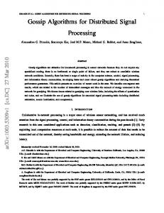
Figure 1(a) depicts an example of STG, with its initial marking, that will be used along this paper. The example has been taken from [LMBSV92] and speci es the behavior of a PLA Interface circuit. Figure 1(b) shows all the SMCs, while the State Graph with its USC con icts is shown in gure 2. 4
Ri+ Ri+ p0
p2
p0
Ri-
Ri+ p2
Ro+ p1
p3
Ai+
p7
p0
Ri-
Ro+ p3
p5
AiRo-
(a)
p6
p1
SM0
Ai-
Ai+ p4
Ro+
Ro-
p4 p4
p7
Ai+
p5
SM1 (b)
Ro-
SM2
p6
Ai-
s1 110 Ri-
RiAi-
s3 010 Ri+
Ri Ai Ro
s4 000
Ri+
s5 110
Ai-
Ro+ s7 111
s2 100
s6 100
Ro+ Ai-
s8 Ai+ 101
Ros9 111
Ri-
Ri-
Ri-
s10 Ai011
s11 Ai+ 001
s12 011
Ro-
c+ 0000
d+
s1
0000
s2
0010
s3
0011
c+
c+ 0010
d+
a+
b+
abcd
c-
c-
s4
b+
a+
a+
0011
d+
d-
b-
a-
d-
b-
a-
s6
1001
s10
1101
s11
b1001
1100
s12
d1000
0100
a-
b-
(a)
0101
1101
a-
s8
s9
a+
b+ d-
s7
0111
c-
c-
s5
b+
1011
(b)
s13
p
�
i
V (RiAiRo) f110, 100g
i
C
i
p0 fs5 s6g p1 fs1, s2, s7, s8, s9g p2 fs3, s4, s10, s11, s12g p3 fs7, s8, s10, s11g p4 fs9, s12g p5 fs1, s2, s3, s4g p6 fs1, s3, s5, s7, s10g p7 fs2, s4, s6, s8, s11g
f110, 100, 111, 101, 111g f010, 000, 011, 001, 011g f111, 101, 011, 001g f111, 011g f110, 100, 010, 000g f110, 010, 110, 111, 011g f100, 000, 100, 101, 001g
i
1-0 1-0---1 -11 --0 -1-0-
Table 3: � , V , and C for each place of the PLA Interface circuit i
i
i
Proof: Supouse that S is a live and safe STG with a USC con ict. As we can see in theorem 12, S has a feasible complementary set T � S that does not cover any MGC in S . m is the marking where we can begin to re all transitions in T and m is the marking where all these transitions have just red. As the markings must be di�erent, almoust exists one place p that has a token in m and does not in m . Get one SM-component (SM) that covers this place p with it's sets � and V . The place p is not marked in m , so SM also covers another place p which is marked in m but not in m , so m 2 � and m 2 � . Finally the binary vector v (corresponding to m ) belongs to V and v (corresponding to m ) belongs to V and both are equal, so the intersection between V and V is not empty. Then selecting a set of SMC that completly covers all the places of S , and intersecting the V sets in each SMC, it is possible to nd all the USC con icts in the STG. 2 t a
c
i
c
f
i
i
j
i
i
i
i
j
f
i
i
i
i
i
j
j
j
j
i
i
j
j
j
i
In the example, V3 \ V4 6= ; for SM1 evidences the existence of a potential USC con ict involving places p3 and p4.
3.3 P-time USC Checking Algorithm
Finding V for each place p requires the generation of the complete reachability set R(m ), which can have exponential size. Instead of calculating V for each place p , we nd a cube C that covers all the binary vectors in V . Thus, if C and C are two cubes that cover V and V respectively, then C \ C = ; ) V \ V = ;. Therefore, the USC property can also be checked, according to theorem 15, by comparing cubes. However, note that USC checking by cube comparison is more restrictive than comparison of partitions of binary vectors, i.e., more potential USC con icts can be detected even if they do not exist. In spite of this, the experiments showed that this restriction hardly in uences on the quality of the results. Next, we describe how the covering cubes can be calculated in polynomial time. i
i
o
i
i
j
i
j
i
i
j
8
i
j
i
i
3.3.1 Calculation of Covering Cubes De nition 16 Let S be a live and safe FC net. A pair (t� 2 T , p 2 P ) is called to be concurrent ((t�,p)2 co(S)) if 9m 2 R(m ) such that t� is enabled, m (p) = 1 and t� 2= p� . Otherwise they are in con ict1 ((t�,p)2 cf(S)). n
c+
d-
a+
b+
e+
c-
a-
b-
e+ d+
o
n
conservative we consider O(n4) (see section 5). Procedure 3.2 describes the O(jPj2 jS j) algorithm that checks the USC property by comparing cubes. Table 4 presents the concurrent and con ict relations for the example, while table 3 shows the resulting covering cubes. t a
Procedure 3.1 : p f
nd cube covering place
( i) /* Let S be the STG with inital marking o, (S) the conflict set of S, and i the cube that covers signal j a t � i ( �j ) a j S from p o i is marked; S from some �j is enabled; t p
g
m
cf C foreach t 2 S do if 8t 2 S ; (t ; p ) 2 cf (S) f m = re m until p m = re m until t if ( t�jj is a rising transition) Cij = 0; else Ci = 1; g else Cij = ?;
Vi
Procedure 3.2 : check usc property
g
(STG,
�) f
foreach SM-component SMi 2 � do foreach place pj 2 SMi do foreach place pk 2 SMi do if ((j > k) and (Cj \ Ck 6= ;))then return false; return true; T � P p0 p1 p2 p3 p4 p5 p6 p7 Ai+ AiRo+ RoRi+ Ri-
cf co cf cf cf cf
co co cf co cf cf
co co cf co cf cf
cf co cf cf cf co
cf cf cf cf cf co
cf co cf cf cf co
cf cf co cf co co
cf cf co cf co co
Table 4: Concurrent and con ict relations.
10
*/
4 Insertion of State Signals
4.1 USC Con ict Graph
De nition 17 For each SM-component SM of an STG S we de ne the Con ict Graph CG(SM) as the pair hP ; Ui, where P is the set of places of S and U � (P�P ) is the USC con ict relation, de ned as follows: (p ; p ) 2 U , C \ C = 6 ;. i
j
i
j
Procedure 4.1 : � f
build con ict graph
(STG, )
foreach SM-component SMi 2 � f let CGi be the conflict graph of the SM-component SMi ; foreach place pj do addVertex(CGi,pj ); foreach place pj do foreach place pk do if ((j > k) and (Cj \ Ck 6= ;))then addEdge (CGi,pj ,pk); g
g
Given a set of SMCs, �, that cover S, the Con ict Graphs (CGs) derived from � de ne all pairs of places with potential USC con icts. Procedure 4.1 describes the O(jPj2 jS j) algorithm that builds the CG for each SMC in �. The technique we propose is based on inserting state signal transitions for each SMC with con icts. However, the information given by all the CGs is redundant, as we will show with the following theorem. t a
Theorem 18 Let S be a live and safe STG and � a set of SMCs that completely covers S . Then S has the USC property if (su�cient condition)
8p 2 P 9 SM 2 � ^ p 2 SM such that 8p 2 SM ; i 6= j; C \ C = ;. Proof: We will prove that if S does not have the USC property, then there is a place p such that for all the SMCs SM that cover p , C \ C = 6 ; for some j =6 i covered by SM . Let us assume that M1 and M2 are two di�erent markings with the same coding, and p a place such that M1 (p ) = 1 and M2(p ) = 0. Since every marking has one token in every SMC, for each SM there is a place p such that M2 (p ) = 1. Since M1 and M2 have the same coding, then C \ C = 6 ;. 2 i
k
i
k
j
k
i
j
i
k
i
i
j
k
i
i
k
i
i
j
j
j
From the previous theorem we can deduce that if for a place p we can nd an SMC without any edge (p ; p ) in its CG, then p does not generate any USC con ict. Therefore, all the edges (p ; p ) in the rest of CGs can be eliminated. Procedure 4.2 presents a O(jS j3) algorithm to reduce the redundancy of the CGs. Figure 5 depicts the potential con icts for each SMC of the PLA Interface circuit, and the edges of the Con ict Graph eliminated after redundancy reduction. i
i
i
j
i
k
t a
11
4.2 State Signal Insertion Procedure
After redundancy reduction, signal transitions are inserted for those SMCs that still have potential USC con icts. Each inserted state signal partitions the SMC into two sets of places. De nition 19 A place p of an SMC is in the On-set (O�-set) of an inserted signal t , if p is located between a rising (falling) and a falling (rising) transition of t . A potential USC con ict in an SMC can be disambiguated by inserting a state signal in such a way that each of the involved places is located in a di�erent set. Moreover, the same signal can be used to disambiguate multiple con icts at the same time. i
j
i
j
Procedure 4.2 : redundancy reduction
(STG,
�) f
foreach place pi 2 STG dof processed(pi) = deleted(pi) = false; g foreach place pi 2 STG do foreach SM-component SMl 2 � do if ((pi 2 SMl ) and (numOfEdges (CGl,pi) = 0)) deleted(pi) = true; foreach place pi 2 STG do if (deleted(pi) = true) foreach SM-component SMl 2 � do if (pi 2 SMl ) deleteAllEdges(CGl,pi); repeat f SMmax = none; max = 0; foreach SM-component SMl 2 � dof n = 0; foreach place pi 2 SMl do if ((deleted(pi)6= true) and (processed(pi)6= true)) n++; if ( n > max ) f max = n; SMmax = SMl ;g g if ( SMmax 6= none ) foreach place pi 2 SMmax do processed(pi) = true; foreach SM-component SMl 2 � ? SMf maxg do foreach edge (pi; pj ) 2 SMl do if ((deleted(pi) = true) or (deleted(pj) = true)) deleteEdge(pi,pj ,CGl ); g until(SMmax = none);
g
4.2.1 SMC Bipartitioning
To insert a state signal t in an SMC, the set of places must be partitioned into the On-set and the O�-set of t. Then, a transition t+ (t?) must be inserted for each pair of consecutive places (p ; p ) such that p 2 O�-set(t) (On-set(t)) and p 2 On-set(t) (O�-set(t)) (note that more than one pair of t+ and t? transitions may be required). In our approach we use a Fiduccia&Mattheyses-based algorithm [FM82], with a cost function that aims at: i
j
i
j
12
Ri+
USC conflict USC conflict eliminated after redundacy reduction
Ri Ai Ro
p0 C0 = 1-0
p2
Ri+
Ro+
C2=0 - -
p7
p0
C3=- -1
C0 = 1-0
Ri-
C7=-0-
Ai+
p3
Ai+
Ai-
p4
Ro+
C4=-11
p4 C4=-11
p1
Ro-
p6 C6=-1-
Ro-
C1=1- -
p5 C5=- -0
SM0
SM1
SM2
Ri+
s+ Ri Ai Ro
p0 C0 = 1-0
Ri+
Ro+ p3 C3=- -1
Ro+ s-
Ai+ p4 C4=-11
Ai+
RoRop5 C5=- -0
SM
On-set Off-set
USC conflict
Then the cost function gain is zero, since all places which were in the On-set at the beginning are now in the O�-set and viceversa. The cost of each new partition is monitored by computing
X G = D k
k
=1
i
i
where k is the number of movements attempted and D is the gain of the i-th movement. The set of movements nally implemented are those that correspons to the maximum value of the cost function, i.e., to the maximum of the gain i
max G k
k
The operations are repeated on the new partition, until convergence is reached, i.e., until the maximum value of the cost correspons to the initial partition.
Procedure 4.3 : add internal signals
(STG,
i = 0;
�) f
foreach SM-component SMl 2 � dof while (number of edges in CGl > 0) dof let � = initialPartition (CGl ); repeat f G0 = 0; k = 1; �tmp = �; repeat f foreach pj 2 SCl dof
g
g
g
D(pj ; �tmp) = Ic (pj ; �tmp) ? Ec (pj ; �tmp ) + Et(pj ; �tmp) ? It (pj ; �tmp ); pmaxk = pj j 8pi 2 SMl : D(pj ; �tmp ) > D(pi ; �tmp ); Gk = Gk?1 + D(pmaxk ; �tmp ); movePlace (pmaxk , �tmp ); k = ++; guntil(all pj 2 SMl have been moved) let Gmax = maxk Gk ; k = 0; while(Gk 6= Gmax) do f movePLace (pmaxk+1, �); k + +; g guntil(G0 = Gmax ) t
addNewSignal ( i ,STG); insertTransitions ( i , ,STG); deleteSolvedConflicts ( , l ); ;
i++
t �
� CG
Procedure 4.3 inserts state signal in each SMC of � until all the potential USC con icts are eliminated. Its complexity, when executed for all the SMC is O(jPj3) [FM82] (see section 5). 15
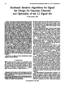
After state signal insertion, a postoptimization step to increase the parallelism of the STG is performed. It consists in moving the inserted transitions in such a way that they can be executed in parallel with those places that had no con icts in the original SMC. Figure 6 shows how an SMC component is partitioned and a state signal inserted to eliminate the USC con icts in the example. The obtained solution ( gure 7) is the same than that presented in [LMBSV92].
s+ Ri-
Ri+ Ro+ sAi+ Ro-
Ai-
Step time-complexity cf(S) calculation O(n3) C calculation O(n4) SMC calculation [Hac72] O(n2) CG calculation O(n2) State signal insertion O(n3) i
Table 5: Complexity analysis for the USC procedure. STG sig alloc-outbound 7 nak-pa 9 ram-read-sbuf 10 sbuf-ram-write 10 sbuf-read-ctl 6 sendr-done 3 atod 6 vbe4a 6 vbe6a 8 master-read 13 gcd alu 8 gcd reg a 20 gcd reg b 18
inital nal [LMBSV92] nal tr states SM sig tr lit time sig tr lit time 18 17 1 9 22 19 6 9 22 26 0.6 18 56 4 10 22 30 9.9 10 20 24 0.7 20 36 4 11 22 20 8 11 22 24 1.0 20 58 3 12 24 30 11.5 12 24 23 1.4 12 14 2 7 14 13 5.2 7 14 15 0.3 6 7 2 4 8 5 3.5 4 8 8 0.1 12 20 3 7 14 14 5.2 7 14 13 0.2 12 76 3 8 16 22 10.1 8 16 31 0.3 16 128 3 10 20 30 18.4 10 20 38 0.7 26 8932 8 16 36 77 1635.1 15 30 46 2.5 16 228 4 - - - 11 22 35 0.7 58 1274 5 - - - 25 75 84 29.9 54 1146 5 - - - 23 69 97 21.5
Table 6: Experimental Results For all the benchmarks (except for master-read) the number of inserted signals is the same for both techniques. For nak-pa our procedure inserts fewer transitions. After forcing the USC property, we used the SIS sequential synthesis system developed at U.C. Berkeley to implement the circuit and obtain the number of factored form literals. The CPU times are not comparable, since [LMBSV92] includes CSC and synthesis time, while we only consider CSC time (executed on a SPARC IPX with 32 Mbyte main memory). We show that good-quality results can be obtained with short CPU times. Surprisingly, our procedure found out, after 2.5 sec of CPU time, a solution to the masterread only inserting two state signals, while in the results presented by [LMBSV92] three state signals were to be inserted. This result made evident the promising suitability of our approach for large STGs. Finally, the last two rows present results on the largest STGs we have encountered so far. They represent a good sample of the type of circuits that can be automatically generated by synthesis tools. Both required ve state signals that were inserted in less that 30 secs. 17
7 Conclusions and future work We have presented a P-time algorithm to solve the Unique State Coding problem for STGs. Unlike other techniques used for the same problem, only the STG representation is required for the algorithm. State disambiguation is performed by the insertion of state signals. The results obtained from several experiments show that our approach, with short CPU times, improves the quality of the solutions obtained by other existing techniques. Several open issues are left for the future. In the area of USC, we are exploring more precise algorithms to detect con icts, increase the concurrency of the STGs, reduce the complexity of the synthesized circuit, and extend our approach to any class of Petri nets. On the other hand, we believe that more e�ort must be invested in devising P-time algorithms for the synthesis of STGs, especially for those synthesis systems that generate large and complex STGs automatically.
Acknowledgment
We would like to thank Cho W. Moon for his help in using SIS and providing the benchmarks used in the report.
References [CB92]
Jordi Cortadella and Rosa M. Badia. An asynchronous architecture model for behavioral synthesis. In Proc. of the European Design Automation Conference, pages 307{311, March 1992. [Chu87] Tam-Anh Chu. Synthesis of Self-timed VLSI Circuits from Graph-theoretic Speci cations. Ph.d. thesis, MIT, June 1987. [FM82] C.M. Fiduccia and R.M. Mattheyses. A linear time heuristic for improving network partitions. In Proc. of the 16th Design Automation Conference, 1982. [Hac72] M. Hack. Analysis of production schemata by Petri nets. M.s. thesis, MIT, February 1972. [KKT91] M.A. Kishinevsky, A.Y. Kondratyev, and A.R. Taubin. Formal method for selftimed design. In Proc. of the European Design Automation Conference, pages 197{201, February 1991. [LKSV91] L. Lavagno, K. Keutzer, and A. Sangiovanni-Vincentelli. Algorithms for synthesis of hazard-free asynchronous circuits. In Proc. of the 28th. Design Automation Conference, pages 302{308, June 1991. [LMBSV92] Luciano Lavagno, Cho W. Moon, Robert K. Brayton, and A. SangiovanniVincentelli. Solving the state assignment problem for signal transition graphs. In Proc. of the 29th. Design Automation Conference, June 1992. [MBM89] Teresa H.-Y. Meng, Robert W. Brodersen, and David G. Messerschmitt. Automatic synthesis of asynchronous circuits from high-level speci cations. IEEE Trans. on CAD, Vol. 8(11):1185{1205, November 1989. 18
[MSB91]
Cho W. Moon, Paul R. Stephan, and Robert K. Brayton. Synthesis of hazard-free asynchronous circuits from graphical speci cations. In Proc. of ICCAD-91, pages 322{325, November 1991. [Mur89] Tadao Murata. Petri Nets: Properties, analysis and applications. Proceedings of the IEEE, Vol. 77(4):541{574, April 1989. [Van90] P. Vanbekbergen. Optimized synthesis of asynchronous control circuits from graphtheoretic speci cation. In Proc. of the Int. Conf. on Computer-Aided Design, pages 184{187, November 1990. [VLGM92] P. Vanbekbergen, B. Lin, G. Goossens, and H. De Man. A generalized state assignment theory for transformations on signal transition graphs. In Proc. of the Int. Conf. on Computer-Aided Design, pages 184{187, November 1992.
19