Jürgen Becker, Reiner W. Hartenstein, Michael Herz, Ulrich Nageldinger: Parallelization in Co-Compilation for Configurable Accelerators; in proccedings of Asia and South Pacific Design Automation Conference, ASP-DAC’98, Yokohama, Japan, Feb. 10-13, 1998
Parallelization in Co-Compilation for Configurable Accelerators A Host / Accelerator Partitioning Compilation Method
J. Becker
R. Hartenstein, M. Herz, U. Nageldinger
Microelectronics Systems Institute Technische Universitaet Darmstadt (TUD) D-64283 Darmstadt, Germany Phone: +49 6151 16-4337 Fax: +49 6151 16-4936 e-mail:
[email protected] http://www.microelectronic.e-technik. tu-darmstadt.de/becker/becker.html
Computer Structures Group, Informatik University of Kaiserslautern D-67653 Kaiserslautern, Germany Fax: +49 631 205 2640 Home fax: +49 7251 14823
[email protected] http://xputers.informatik.uni-kl.de
Abstract— The paper introduces a novel co-compiler and its “vertical” parallelization method, including a general model for co-operating host/accelerator platforms and a new parallelizing compilation technique derived from it. Small examples are used for illustration. It explains the exploitation of different levels of parallelism to achieve optimized speed-ups and hardware resource utilization. Section II introduces novel vertical parallelization techniques involving parallelism exploitation at four different levels (task, loop, statement, and operation level) is explained, achieved by for configurable accelerators. Finally the results are illustrated by a simple application example. But first the paper summarizes the fundamentally new dynamically reconfigurable hardware platform underlying the co-compilation method.
1st Design Crisis
standardized
standard memory, transistors, micronand, nor.. 1967 processor 1957 (TTL) customized 1977p pro
customized application of transistor and
integrated circuit.
2nd Design Crisis
I. INTRODUCTION Tsugio Makimoto has observed cycles of changing mainstream focus in semiconductor circuit design and application [1] (fig. 1). Makimoto’s model obviously assumes, that
each new wave is triggered by a paradigm shift. The second wave has been triggered by shifting from hardwired to programmable microcontroller. The third wave will be triggered by shifting to using reconfigurable hardware platforms as a basis of a new computational paradigm. Makimoto’s third wave takes into account that hardware has become soft. Emanating from field-programmable logic (FPL, also see [2]) and its application the awareness of the new paradigm of structural programming is growing. Commercially available FPGAs make use of RAM-based reconfigurability, where functions of circuit blocks and the structure of their interconnect is determined by bit patterns having been downloaded into “hidden RAM” inside the circuit. Modern FPGAs are reconfigurable within seconds or milliseconds, even partially or incrementally. Such “dynamically reconfigurable” circuits may even reconfigure themselves. An active circuit segment programs an idling other segment. So we have two programming paradigms: programthe future? ming in time and in space, distinguishing two kinds of “software”: reconfigurable dynamically year
1987 customized 1997 p str ro c e rog uct for TV, clock, (co gr du logic (ASIC), i (co ramura i a n m n t mp r m calculator, add-on sp pu mi al mi l im uti a t etc. chips ce ing ng e) ng ng )
accelerators outsourcing: paradigm shift: crisis symptom: system vendor to hardware to component vendor software migration
limitations of the
microprocessor
paradigm shift: procedural to structural migration
paradigm:
new paradigm:
algorithm: fixed
algorithm: variable
algorithm: variable
resources: fixed
resources: fixed
resources: variable
new paradigm:
Fig. 1: Makimoto’s wave: summarizing the history of paradigm shifts in semiconductor markets.
Xputer Lab
n sequential
software (code downloaded to RAM)
n structural
software (downloaded to hidden RAM)
But Makimoto’s third wave is heavily delayed. FPGAs are available, but are mainly used for a tinkertoy approach, rather than for a new paradigm. Is it realistic to believe, that Makimoto’s third wave will come? If yes, what is the reason of its delay? Although FPGA integration density has passed that of microprocessors, the evolution of dynamically reconfigurable circuits is approaching a dead end. For a change new solutions are needed for
Notice: This document has been provided by the contributing authors as a means to ensure timely dissemination of scholarity and technical work on a noncommercial basis. Copyright and all rights therein are maintained by the authors or by other copyright holders, notwithstanding that they have offered their works here electronically. It is understood that all persons copying this information will adhere to the terms and constraints invoked by each author's copyright. These works may not be reposted without the explicit permission of the copyright holder.
Jürgen Becker, Reiner W. Hartenstein, Michael Herz, Ulrich Nageldinger: Parallelization in Co-Compilation for Configurable Accelerators; in proccedings of Asia and South Pacific Design Automation Conference, ASP-DAC’98, Yokohama, Japan, Feb. 10-13, 1998
1012 transistors/chip (the “roadmap” prediction for microprocessors is too optimistic)
109
16G 4G 1G 256M 64M n 16M esig
ry d mo 4M e m 1M 256k P5 α P-II 106 6 6 8 64k 80 80 04 436802386 30 0 e 4k16k d 2 6 0 ca 80 800 de r) 1k or / 0 8 8 80 08 6 ess 00 / yea c 1 8 5 o 3 pr 10 × 1,6 40 008 80 cro 04 (× mi
1960
1970
1980
1990
2000
Xilinx: “perhaps”
or em m
109
Progress: parallel to Gordon Moore Curve
Transistor count exceeds that of the microprocessor
2010
some fundamental issues [3]. This paper analyzes the state of the art and introduces a fundamentally new approach, which has to cope with: n a hardware gap n a modeling gap n a software gap n an education gap A. The Hardware Gap Comparing the Gordon Moore curve of integrated memory circuits versus that of microprocessors and other logic circuits (fig. 2) shows an increasing integration density gap, currently by about two orders of magnitude. We believe, that the predictions in fig. 2 [4] are more realistic than the more optimistic ones of Semicon’s “road map” [5] (also [6]). A main reason of this gap is the difference in design style [7]. The high density of memory circuits mainly relies on full custom style including wiring by abutment. Microprocessors, however, include major chip areas defined by standard cell and similar styles based on “classical” placement and routing methods. This is a main reason of the density gap, being a design gap. Another indication of increasing limitations of microprocessors is the rapidly growing usage of add-on accelerators: both boards and integrated circuits. Both, standard cell based ASICS and FPGAs ([2], [8]), are usually highly area-inefficient, because usual placement algorithms use only flat wiring netlist statistics being much less relevant than needed for good optimization results. A much better placement strategy would be based on detailed data dependency data directly extracted from a high level application specification, like in synthesis of systolic arrays ([9],[10],[11]), where it’s derived directly from a mathematical equation system or a high level program (“very high level synthesis”). Due to full custom design style FPGA integration density (fig. 3) grows very fast (at a rate as high as that of memory chips) and has already exceeded the of general purpose microprocessors [12]. But in FPGAs the reconfigurability overhead is very high (fig. 4). Figures having been published indicate 200 physical transistors needed for a logical transistor ([13],[14]) or, only 1% of chip area is available for pure application logic [15]. Routing takes up to hours of
y FP
FPGA pre-design is of full custom style
2: The Gordon Moore curve and microprocessor curve - with design gap [4].
Xputer Lab
Xilinx: “planned”
gap
year to market
100
Fig. 3: FPGA high growth 1012 transistors/chip rate of integration density — compared to memory and Xilinx fabricated microprocessor.
s GA
cessor Micropro 106 year 1990
2010
2000
computation time and uses only part of the logic elements — in some cases even only about 50%. So FPGAs would hardly be the basis of the mainstream paradigm shift to dynamically reconfigurable, such as e. g. predicted by Makimoto’s wave [1] (also see analysis in [7]). The reason of the immense FPGA area inefficiency is the need for configuration memory and the extensive use of reconfigurable routing channels, both being physical reconfigurability overhead artifacts. B. Closing the Hardware Gap An alternative dynamically reconfigurable platform is the KressArray [16], being much less overhead-prone and more area-efficient than FPGAs by about 3 orders of magnitude (fig. 5). (This high density may be reason to need low power design methods [18]). Also the KressArray integration density is growing a little faster than that of memories (fig. 5). The high logical area efficiency is obtained by using multiplexers inside the PEs (processing elements) instead of routing channels. Fig. 6 illustrates a 4 by 8 KressArray example. Fig. 8 illustrates the mapping (fig. b) of an application (fig. a: a system of 8 equations) onto this array. The Kress Array is a generalization of the systolic array — the most area-efficient and throughput-efficient datapath design reconfigurability overhead in FPGAs: logical chip area uses only 1% of physical chip area [DeHon] - 1 logical transistor per 200 physical transistors [Tredennick]
1012 transistors/chip
y or em m
109
GA FP
s
al ic s y ph
esso Microproc 106
Fig. 4: The hardware gap of reconfigurability: physical versus logical integration density of FPGAs — compared to microprocessors and memory chips.
Tr
De
103
r
n Ho
l As G FP
ic og
ck ni en d e
al
year 1990
2000
Notice: This document has been provided by the contributing authors as a means to ensure timely dissemination of scholarity and technical work on a noncommercial basis. Copyright and all rights therein are maintained by the authors or by other copyright holders, notwithstanding that they have offered their works here electronically. It is understood that all persons copying this information will adhere to the terms and constraints invoked by each author's copyright. These works may not be reposted without the explicit permission of the copyright holder.
2010
Jürgen Becker, Reiner W. Hartenstein, Michael Herz, Ulrich Nageldinger: Parallelization in Co-Compilation for Configurable Accelerators; in proccedings of Asia and South Pacific Design Automation Conference, ASP-DAC’98, Yokohama, Japan, Feb. 10-13, 1998
1012 transistors/chip
KressArray: logical integration density is larger than that of FPGAs by about 3 orders of magnitude
109
m
o em
y ra r A ss e Kr
ry
Micropro
cessor
106
Fig. 5: Closing the hardware gap: KressArray logical integration density — compared to microprocessors, FPGA and memory.
Tr
De
n Ho
s GA P F
ick nn e ed
l ca gi o l
years
103 1990
2000
2010
style known, using wiring by abutment of extremely optimized full-custom essential cells, and, providing massively pipelined highly parallel solutions for highly sophisticated application algorithms like systems of equations. Systolic array methodology also includes formal design problem capture at very high level (e. g. equation systems) and elegant and concise formal synthesis methods. The limited applicability of systolic arrays to only a small class of applications with regular data dependencies (“systolizable algorithms”) is not due to its physical layout and organizational principles. The limitations are caused just by the narrow-minded mathematics-based synthesis methods (linear projections only), traditionally used for systolic arrays, where reconfigurability would not make sense because of uniformity of its highly regular results of perfectly regular interconnect: linear full length pipes only, all PEs (processing elements) having exactly the same function, etc. By discarding the projection method and replacing it by an optimizer the design space is widened by orders of magnitude. Now reconfigurability makes sense. Results are no longer uniform. Highly flexible hardware is needed. KressArray consequences are: applications: interconnect [7]: interconnect: PE functions: pipeline shape:
any — no restrictions programmable at 5 levels no restrictions: globally, locally & in PE individual locally individual, also routing free form: meandering, zig zag, spiral, feed back, forks, joins, ....
As an optimizer Kress uses a mapper called DPSS (data path synthesis system), being a simulated annealing optimizer [16]. Configuration code is conveyed by wormhole routing [17], which is supported by KressArray hardware. Because of the absence of routing channels the structure synthesis is carried out by a placement-only algorithm. Kress uses a simulated annealing optimizer [16]. No netlists are used: data dependency data are fully preserved to obtain optimum placement results.
Xputer Lab
The mapping problem has been mainly reduced to a placement problem. Only a small residual routing problem goes beyond nearest neighbor interconnect, which uses a few PEs also as routing elements. DPSS includes a data scheduler to organize and optimize data streams for host/array communication, being a separate algorithm carried out after placement [16]. Instead of hours known from FPGA tools DPSS needs only a few seconds of computation time. Permitting alternative solutions by multiple turn-around within minutes the KressArray tools support experimental very rapid prototyping, as well as profiling methods for known from hardware/software co-design (also see section II ff.). In coarse granularity reconfigurable circuits like Kress-Arrays “long distance” interconnect is much cheaper and shorter than known from bit-level abutment arrays ([19] e. g. like in Algotronix FPGAs). The original Kress-Array architecture [16] has evolved to newer architectures ([7], [20]), also supporting “soft” implementations of data sequencers and other feedback datapaths, as well as of systolic arrays (this novel systolic array synthesis method is a by-product of Kress’ DPSS). C. Closing the Software Gap The area of conventional (fine granularity like FPGAs) fieldprogrammable logic (also see [2]) suffers also from a software gap [21]: only a few application development tools are available, which are difficult to use. Using reconfigurable platforms currently available commercially is mainly based on tinkertoy approaches at glue logic level. To much hardware expertise, and even also routing and placement expertise is needed for structural software implementations. We need much more powerful application development support environments, like compilers accepting application problems expressed in programming languages, like C or Java. But such structural software compilers are currently not available. Previous section “The Hardware Gap” has also shown, that for shifting from systolic array to the much more flexible KressArray this hardware gap has been partially closed by a fundamentally different synthesis method (from mathematical methods to simulated annealing), i.e. by closing a software gap at a lower level. The achievement is the novel method of combination, since simulated annealing per se is not new. But, although Kress’ DPSS accepts C language sources it is mainly a technology mapper. It does not fully bridge the coarse granularity software gap. New software is also needed for integration into the usually embedded application environment, where automation of host/accelerator partitioning and other support is highly desired [3] (also see fig. 7). R&D in Custom Computing Machines (CCMs: [22]), such as FCCMs (FPGA-based CCMs [23] [24]), deals with architectures and applications of dynamically reconfigurable accelerators. In some CCM architectures accelerators support a host, like e. g. a PC or workstation, so that two separate programming paths are included (also see fig. 7), n traditional
(sequential) software running on the host,
n structural
software running on a reconfigurable accelerator co-processor.
The conclusion is, that the implementation of such dichotomous configware/software systems is a hardware/software
Notice: This document has been provided by the contributing authors as a means to ensure timely dissemination of scholarity and technical work on a noncommercial basis. Copyright and all rights therein are maintained by the authors or by other copyright holders, notwithstanding that they have offered their works here electronically. It is understood that all persons copying this information will adhere to the terms and constraints invoked by each author's copyright. These works may not be reposted without the explicit permission of the copyright holder.
Jürgen Becker, Reiner W. Hartenstein, Michael Herz, Ulrich Nageldinger: Parallelization in Co-Compilation for Configurable Accelerators; in proccedings of Asia and South Pacific Design Automation Conference, ASP-DAC’98, Yokohama, Japan, Feb. 10-13, 1998
reconfigurable interconnect
bus •• •
Fig. 6: example of a KressArray (buses not shown).
co-design problem, so that hardware experts are needed to “program” such platforms. To close this software gap to provide easy access by programmers a co-compiler is needed for automation of such soft-hardware/software co-design. This new software has to cope a new class of parallelism, other than in classical parallel computing or glue logic design. It has to manage vertical and horizontal parallelization. Exploiting such parallelism with optimized code transformations in structural programming requires new parallelizing compilation techniques. In traditional parallelizing compilers loop optimization techniques transform sequential loops (on process level) into parallelized loops (also at process level). This type of parallelization we call “horizontal parallelization”. In contrast, parallelizing loops in structural programming performs a “vertical” move, one abstraction level down: sequential loops (process level ) are transformed into parallelized loops (data-path level ) [25]. This parallelization we call “vertical parallelization”. Subsections D thru F of section II of this paper introduce a method to bridge the gap. D. Closing the Modeling Gap The areas of custom computing machines [26], as well as of hardware/software co-design [27] are incoherent since being torn apart by the wide variety of architectures. A general common model has been missing: the modeling gap. But for custom computing machines using coarse granularity dynamically reconfigurable datapaths like the KressArray now also a new fundamental machine paradigm is available ([28], [29]), This new paradigm might also be used for hardware/software co-design. To implement the integration of such soft ALUs like the KressArray into a CCM, a deterministic data sequencing mechanism is also needed, because the traditional so-called von Neumann paradigm does not support “soft” datapaths [30], because of the tight coupling between instruction sequencer and ALU [31]. As soon as a data path is changed by structural programming, a “von Neumann” architecture falls apart and requires a new instruction sequencer. high level programming language source (e. g. : C) partitioning co-compiler host code accelerator (sequential) configuration code microprocessor or dynamically reconfigurable microcontroller (host) accelerator(s) Fig. 7: Co-compilation supports host/accelerator application development.
Xputer Lab
c0 2*
rALU
reconfigurable ALU
y11 := a1 * (y10 + 2 * c1); y21 := 5 * y20 + e1 + (f1 + y10); y31 ;= y30 * (y40 + 2 * e1); y41 := (5 * y20 + e1) * f1;
y10 := a0 * (b0 + 2 * c0); y20 := 5 * d0 + e0 + (f0 + b0); y30 := g0 * (h0 + 2 * e0); a) y40 := (5 * d0 + e0) * f0;
b0 + bus
c1 2* a0 *
a1 *
b0 f0 + y11
+ b)
e0 2*
e0 +
+ y10
f1 + temp
d0 5*
y21
h1 + y20 e1 + 5* +
e1 2* f0 *
+
g0 y40 * * f1 y30 y31 * temp y41
Fig. 8: A KressArray DPSS mapping example: a) application, b) result.
The solution is the use of data sequencers [32] instead of an instruction sequencer. The new computational paradigm thus obtained (published elsewhere [28], [30], also see figure 9) is the counterpart of the traditional computer paradigm, not supporting reconfigurable data paths [20]. This paradigm provides an innovative basic model for a new direction of parallel computing ([33], [34], [35]). Details and principles of the new paradigm have been published elsewhere ([28], [29], [36]). It is good backbone paradigm to close the software gap for both, coarse granularity dynamically reconfigurable platforms, as well as for the development of co-compilation methods. E. Closing the Education Gap Current computer science curricula do not create awareness, that hardware has become soft, nor, that hardware, structural and sequential software are alternatives to solve the same problems. Lack of awareness is blocking the paradigm shift. Intel has given courses to teach 250,000 people to enable the paradigm shift from hardwired electronics to microcontroller, what has been needed to create a market for microprocessors. A new machine paradigm, as universal as the computer [28], ready for the next paradigm shift. Section II summarizes new parallelizing compilation techniques to enter this new world of computing. Principles and applications of dynamically reconfigurable circuits as a basis of the new paradigm of structural programming should be included in academic main courses to remove the mental barriers blocking the paradigm shift. But with reconfigurable platforms and related programming tools available today such a paradigm shift is not likely to happen. To create innovative expertise and awareness in many application areas new equipment of next generation reconfig-
(multiple) Data Sequencers
reconfigurableKress ALU Array ( e. g. KressArray rALU Array)
decision data smart (loosely smartinterface interface (generic) coupled) data streams address sequences 2-D Data in te rle Memory a v ed Fig. 9: Xputers: basic block diagram reflecting the basic machine principles.
Notice: This document has been provided by the contributing authors as a means to ensure timely dissemination of scholarity and technical work on a noncommercial basis. Copyright and all rights therein are maintained by the authors or by other copyright holders, notwithstanding that they have offered their works here electronically. It is understood that all persons copying this information will adhere to the terms and constraints invoked by each author's copyright. These works may not be reposted without the explicit permission of the copyright holder.
Jürgen Becker, Reiner W. Hartenstein, Michael Herz, Ulrich Nageldinger: Parallelization in Co-Compilation for Configurable Accelerators; in proccedings of Asia and South Pacific Design Automation Conference, ASP-DAC’98, Yokohama, Japan, Feb. 10-13, 1998
urable platforms should be distributed in academia and research institutes, as well as new application development support software, such as e. g. introduced by this paper. Since this new area is immature, many highly significant results are expected: motivating a new generation of researchers.
normal programmer
expert user
a)
MoPL
co-compiler
Optimizing Partitioner
F. A new Class of Custom Computing Machines Not only in desktop or embedded systems the microprocessor’s role is changing. More and more silicon area is occupied by application-specific add-on accelerator silicon [7] (for graphic, multimedia, image (de-) compression etc.), much more area than for the microprocessor itself (4th phase in fig. 1). Designing microprocessor-based systems has become a hardware/software co-design problem in general. That’s why for bridging the software gap we need more than just compilers accepting high level language sources. We need a co-compile (i. e. a partitioning compiler) providing code for both, accelerator and host (fig. 7). The co-compilation environment introduced by this paper supports accelerators based on a novel machine paradigm (the Xputer paradigm [28] [29] [36]). This is a new class of CCMs, a major step forward beyond contemporary CCMs being a tinker toy approach.
II. PARALLELIZING AND PARTITIONING CO-COMPILATION Structural software being really worth such a term would require a source notation like the C language and a compiler which automatically generates structural code from it. For such a new class of accelerator hardware platforms a completely new class of (co-) compilers is needed, which generate both, sequential and structural code: partitioning compilers, which separate a source into two types of cooperating code segments ([37], [38]): n structural software for the accelerator(s), and n sequential software for the host. In such an environment parallelizing compilers require two levels of partitioning: n host/accelerator (or sequential/structural software) partitioning for optimizing performance, and n a structural/sequential partitioning of structural software (second level) for optimizing the hardware/ software trade-off of the Xputer resources. For Xputer-based accelerators the partitioning application development framework CoDe-X (co-design for Xputers) is being implemented, based on two-level hardware/software codesign strategies [25], [39]. CoDe-X accepts X-C source programs (Xputer-C, figure 10), which represents a C dialect. CoDe-X consists of a 1st level partitioner, a GNU C compiler, and an X-C compiler. The X-C source input is partitioned in a
Xputer Lab
MoPL Compiler
Host Compiler Section b)
MoPL extension ( expert extension)
X-C subset
C
Xputer Compiler Section
Function operator Library library
X-C
X-C subset
Partitioner paritioner
X-C compiler
c)
structural code
Analyzer / profiler Profiler
G. Reconfigurable vs. traditionally parallel By run time to compile time migration reconfigurable platforms lead to implementations avoiding the massive run time switching overhead, known from multi-processor platforms based on traditional forms of parallelism [20] [31]. Such run time to compile time migration is a consequence of parallelism exploitation at different levels of abstraction, than known from traditional parallelism at process level. For more details see following sections.
X-C
Fig. 10: The CoDe-X CoCompilation Framework: a) overview, b) optimizing partitioner, c) accelerator compiler.
C
Host code
Xputer code
DPSS: Data Path Synthesis System X-C subset
sequential code
configuration code
first level into a part for execution on the host (host tasks, also permitting dynamic structures and operating system calls) and a part for execution on the accelerator (Xputer tasks). Program parts for accelerator execution are expressed in a C subset, which lacks dynamic structures and restricts the form of index functions for referencing array variables within loop bodies [25], [40]. At second level such structural software for configurable accelerators can be partitioned by the X-C compiler in a sequential part for the data sequencer(s), and a structural part for the rALU array. By using C extensions within X-C experienced users may handhone their source code by including directly data-procedural MoPL code (Map-oriented Programming Language [25], [39], [41]) into the C description of an application. Also less experienced users may use generic MoPL library functions similar to C function calls to take full advantage of the high acceleration factors possible by the Xputer paradigm (see figure 10). The MoPL language [42] provides an elegant and comprehensible method to systematically express generic data address sequences (“scan patterns”) to run on data sequencers (fig. 9) [32]. With primitives like data goto, data jumps, data loops, parallel data loops, nested data loops etc., such scan patterns are the data-procedural counter part of control flow. Exercising MoPL use gives a feel of the new computational world of the paradigm of structural programming. In subsection A the profiling-driven host/Xputer partitioning is explained first. Section E sketches the 2nd partitioning level integration into the CoDe-X framework, which is realized mainly by the X-C subset compiler [40], and section F describes the
Notice: This document has been provided by the contributing authors as a means to ensure timely dissemination of scholarity and technical work on a noncommercial basis. Copyright and all rights therein are maintained by the authors or by other copyright holders, notwithstanding that they have offered their works here electronically. It is understood that all persons copying this information will adhere to the terms and constraints invoked by each author's copyright. These works may not be reposted without the explicit permission of the copyright holder.
Jürgen Becker, Reiner W. Hartenstein, Michael Herz, Ulrich Nageldinger: Parallelization in Co-Compilation for Configurable Accelerators; in proccedings of Asia and South Pacific Design Automation Conference, ASP-DAC’98, Yokohama, Japan, Feb. 10-13, 1998
data path synthesis system (DPSS) [16], which performs further transformation of derived structural code into loadable rALU array configuration code (fig. 10).
10
T5
20
30
T6
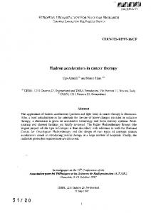
A. Profiling-driven Host/Accelerator Partitioning Exploiting Task Level Parallelism: the profiling-driven first level partitioning of the dual CoDe-X partitioning process is responsible for the decision which task should be evaluated on Xputer-based accelerators and which one on the host. Generally, four kind of tasks can be determined: n host tasks (containing dynamic structures, n Xputer tasks (candidates for Xputer migration), n MoPL-code segments included in X-C source, n generic Xputer library function calls. The host tasks have to be evaluated on the host, since they cannot be performed on Xputer-based accelerators. This is due to the lack of an operating system for Xputers for handling dynamic structures like pointers, recursive functions etc., which can be done more efficiently by the host. The generic Xputer library functions and its MoPL-code segments are executed in any case on the accelerator. All other tasks are Xputer tasks, which are the candidates for the iterative first level partitioning step determining their final allocation based on simulated annealing ([25], [31], [39]). The granularity of Xputer tasks depends on the hardware parameters of the current accelerator prototype, e.g. the maximal nesting depth of for-loops to be handled by data sequencers, the number of available PEs within a KressArray, etc. For all generated tasks corresponding host and/or Xputer performance values are determined, which are used in each iteration of the first level partitioning process for evaluating the complete application execution time, which represents the optimizing goal of this process. For details about performance evaluation in CoDe-X see [25], [43]. Since this host/accelerator partitioning methodology should be independent from an Xputer hardware prototype version, a hardware parameter file controls the partitioning. Thus, CoDe-X partitioning strategies and algorithms can be used also for future accelerator prototypes. Based thereon, the first level partitioning method of CoDe-X can be subdivided into the following major steps: n a compiler front end performs syntax and semantic analysis of X-C input programs including also the verification of correct included MoPL-3 code segments as well as of generic Xputer-library function calls by using a MoPL-3 parser, n a set of tasks is derived from the resulted program graph G (see above listed four kind of tasks), whereas the tasks’ granularity depends on the given Xputer hardware parameters, n a data flow analysis step identifies inter-task data dependencies, resulting in inter-task communications, e.g. memory re-mappings. Output of this step is a task graph representing all task’s control and data dependence relations, n based on the hyperplane concurrency theorem by Leslie Lamport [44], a new vertical hyperplane theorem has been developed [25] for performing optimizing code transformations to appropriate Xputer tasks. So potential intra-task code parallelism can be exploited and optimize the accelerator’s hardware utilization. Correspondingly, the resulting optimized task version(s) are included in an extended task graph,
Xputer Lab
critical_path(T1) = 40 30
20
T9
10
T1
T10 T11
T12
critical_path(T7) = 150
T7
40
T8
Task Graph TG
60
10
20 40
T2
critical_path(T6) = 150
T3 20
T4
Fig. 11: Examples of critical path locations for different tasks Ti of task graph TG. n an application performance analysis
determines the performance values of each task within the extended task graph related to host and/or accelerator execution [25], [43], n the final task allocations of all movable tasks will be decided in an iterative partitioning algorithm based on simulated annealing [25], [31]. The cost function to be minimized during this algorithm is the complete application execution time, which is estimated in each iteration by using the tasks’ determined performance values and considering concurrent task executions, as well as communication-, reconfiguration, and synchronization-overhead during run time, n finally, the task scheduling step computes the scheduling positions of all tasks within their execution queues of the host and Xputer-based accelerator modules, dependent on their data dependencies and critical path location within the task graph (see below). Since this paper focuses on parallelism exploitation by CoDe-X, in the following the necessary code optimization techniques, as well as the implemented task scheduling step are explained. For further details see [25], [31], [39], [43]. B. Code Optimization Techniques at 1st level Partitioning The 1st level partitioner (see optimizing partitioner in figure 10) of the current CoDe-X version applies five different code transformations, dependent on the tasks’ internal data flow situation, as well as on the achievable performance increase and/or the obtained accelerator hardware utilization. Therefore, to identify parallelizable index space subsets within nested loops, Lamport’s hyperplane concurrency theorem [44] has been extended to the vertical hyperplane theorem [25] according to the restricted statical X-C subset of Karin Schmidt’s X-C compiler [40] and its corresponding index space. In general, Lamport’s hyperplane concurrency theorem [44] can be applied to fully-nested loops, which satisfy the assumptions (A1) - (A5), whereas generated variables are a variables on left sides of assignments: (A1) it contains no I/O statement, (A2) it contains no transfer of control to any statement outside the loop, (A3) it contains no subroutine or function call which can modify data,
Notice: This document has been provided by the contributing authors as a means to ensure timely dissemination of scholarity and technical work on a noncommercial basis. Copyright and all rights therein are maintained by the authors or by other copyright holders, notwithstanding that they have offered their works here electronically. It is understood that all persons copying this information will adhere to the terms and constraints invoked by each author's copyright. These works may not be reposted without the explicit permission of the copyright holder.
Jürgen Becker, Reiner W. Hartenstein, Michael Herz, Ulrich Nageldinger: Parallelization in Co-Compilation for Configurable Accelerators; in proccedings of Asia and South Pacific Design Automation Conference, ASP-DAC’98, Yokohama, Japan, Feb. 10-13, 1998
(A4) Any occurrence in the loop body of a generated variable VAR is of the form VAR (e1, ... , er), where each ei is an expression not containing any generated variable, (A5) each occurrence of a generated variable VAR in the loop body is of the form: VAR (Ij1 + m1, ... , Ijr + mr), where the mi are integer constants, and j1, ... , jr are r distinct integers between 1 and n. Moreover, the ji are the same for any two occurrences of VAR. Thus, if a generation A(I2 - 1, I1, I4 + 1) appears in the loop body, then the occurrence A (I2 + 1, I1 + 6, I4) may also appear, but the occurrence A (I1 + 1, I2 + 6, I4) may not. But array variables of transformed loop nests would possibly require index functions, which cannot be expressed in the X-C subset representing structural software. Therefore, in addition to the hyperplane concurrency theorem, two more conditions (S1 and S2, see below) have to be fulfilled for transforming fully-nested X-C subset loops in equivalent X-C subset loop nests (with allowed index functions): (S1) each generated variable VAR, which also appears on the right-hand side of assignment statements, is used within the complete body of a fully-nested X-C subset loop only in the form: VAR(Ijr, . . . , Ijs), 1 ð jr, js ð n, (S1) a generated variables VAR, which appears within the body of a fully-nested X-C subset loop in the form VAR(Ijr+ mjr, . . . , Ijs+ mjs), 1 ð jr, js ð n, and $k Œ {jr, . . . , js} with mk ¦ 0, is not allowed to appear again within this loop body. Based thereon, the vertical hyperplane theorem is formulized in theorem 3-1 as follows: Theorem 0-1: Vertical Hyperplane Theorem Assume that the loop in figure 12 (1) satisfies the assumptions (A1) - (A5), as well as (S1), (S2), and that none of the index variables I1, ... , Ik is a missing variable. Then it can be rewritten into the form of the loop (Par_for_all: for all index points Œ Ik is the loop body parallel executable) given in figure 12 (2). Moreover, the mapping J used for the rewriting is the identity function and can be choose to be independent of the index set I. Note, that in this vertical hyperplane theorem the linear mapping ϑ, used for transforming the index space of the XC subset loop nest, is a special case: the identity function (see figure 12). Thus, the index functions of the resulting loop nest remain unchanged and can be still compiled in executable accelerator code, e.g. in parameters for the data sequencer(s) (performing the variable’s access sequences) and configuration code for the rALU array (implementing the loop body on data path level). Thus, Lamport’s hyperplane concurrency theorem is suitable only for “horizontal parallelization” (process level → process level), whereas the vertical hyperplane theorem is the basis for a “vertical parallelization” of structural software, e.g. X-C subset loops (process level → data-path level). For the proof of the vertical hyperplane theorem and more details about this novel code parallelization method see [25]. Based thereon, the following four parallelizing transformation techniques are applied (see also [45]): n strip
mining: transformation of loop nest with a large index space into several nested loops with smaller index spaces by
Xputer Lab
(1) X-C subset loop nest Conditions to be fulfilled: 1 1 1 for i = c 1 ; i < u 1 ; i ++
• • • •
n n n for i = c ; i < u ; i ++ n n
{
• assumptions (A1) - (A5) of hyperplane concurrency theorem + • extended conditions (S1) and (S2)
loop body } identity function
ϑ: Zn → Zn: ϑ(i1, ..., in) → (i1, ..., in)
(2) Parallelized X-C subset loop nest 1 k k vertically Par_for_all ( i , …, i ) Œ I parallelized for i
k+1
k+1 = ck + 1 ; i < • • • • n n n for i = c ; i < u ; i ++ n n
{ loop body }
uk + 1 ; i
k+1
++
Results: • Par_for_all loop parallelizes for-loops from level 1 to k within above X-C subset loop nest of level n • transformations applicable: + strip mining + loop fusion + loop splitting
Fig. 12: Loop nest transformation à la vertical hyperplane method.
organizing the computation in the original loop into parallel executable chunks of approximately equal size, n loop
fusion: transformation of two adjacent loops into one single loop over the same index space computing the same, which reduces the number of tasks and optimizes therefore the hardware utilization,
n loop
splitting: reverse transformation of loop fusion, which rearranges statement instances in such a way that parts of a loop body are executed for all elements of their index space before other parts that textually follows. Loop splitting can partition one large task into multiple smaller tasks, each to be executed by one accelerator module without reconfiguration,
n loop
interchanging: transformation of a pair of loops by switching inner and outer loop, without affecting the outcome of the loop nest.Loop interchanging supports possible vectorization of the inner loop, and/or parallelization of the outer loop.
The fifth transformation technique implemented by CoDeX’ 1st level partitioner doesn’t require a data flow analysis according to the adapted hyperplane theorem and is called: n loop
unrolling: increasing the step width of single loop iterations and decreasing therefore the total number of iterations, by unrolling the loop body up to a certain factor. This technique is applied for increasing performance and optimizing the accelerator’s hardware utilization, e.g. reducing the number of idle DPUs within a KressArray.
Notice: This document has been provided by the contributing authors as a means to ensure timely dissemination of scholarity and technical work on a noncommercial basis. Copyright and all rights therein are maintained by the authors or by other copyright holders, notwithstanding that they have offered their works here electronically. It is understood that all persons copying this information will adhere to the terms and constraints invoked by each author's copyright. These works may not be reposted without the explicit permission of the copyright holder.
In figure 11 the strip mining application of a computationintensive loop nest within an image smoothing algorithm is shown (see also application example in section III). In our approach the block size of the chunks depends on hardware parameters describing the current accelerator prototype (e.g. the number of available accelerator modules) in order to achieve an optimized performance/area trade-off. This technique can be used e.g. often in image processing applications by dividing an image in stripes of equal sizes in order to manipulate these stripes concurrently on different accelerator modules [39], whereas each strip execution represents one Xputer task. D. Scheduling and Run Time Reconfiguration(s) The Xputer Run-time System (XRTS) [46] provides the software-interface from the host to Xputer-based accelerators. The main purpose of this system is controlling and synchronizing applications executed on the accelerator, but additional features like program debugging are also possible. The Xputer Run-time System can be started interactively or inside a host process and has following features: n XRTS
loads Xputer object files (sequential/structural code for data sequencer(s) / rALU Array)
n XRTS
loads application data binary files with optimized distribution to the memories of different modules to minimize inter-module communication
The run time scheduling process (RTS-process) for performing task scheduling, communication/synchronization and reconfiguration(s) during run time activates the XRTS and is generated by CoDe-X’ 1st level partitioner after the final task allocation and scheduling is determined. For details about the RTS-process and its implementation see [25]. Next, the task scheduling step is described first. This step determines a deadlock-free total execution order of all allocated tasks. Parallel task execution and reconfiguration are possible, according to the detected inter-task data dependencies. Therefore, a static resource-constrained list-based scheduling technique is applied by building a task priority list for each hardware resource, e.g. the host and its connected accelerator modules. A task is inserted into the priority list of its allocated hardware resource according to a two-stage priority function, which is explained below. Since this scheduling problem is NP-complete, appropriate heuristics have been selected for finding a good solution. The list-based scheduling algorithms [47] belong to the heuristic methods. Since it is a very flexible scheduling method, it is described in detail in literature. In our case, a priority function for building a priority list is used to choose
Xputer Lab
mapped for execution
Strip Mining parbegin for (i=0; i