1.6.1.2 Online Rotor Time Constant Estimation Techniques ...................................... 14 .... DC Test of determination of stator resistance. Connect any two stator ..... 97, CHO 99, GOD 99, BAR 99, KAR 97, RIB 00, SEO 01]. 1.6.1.2 Online Rotor ...
A Ph.D. SYNOPSIS in the area of Electrical Machines on the topic
“Parameter Estimation of Three Phase Induction Motor: An Innovative Approach”
Submitted by MAYANK PRATAP SINGH
DEPARTMENT OF ELECTRICAL ENGINEERING FACULTY OF ENGINEERING DAYALBAGH EDUCATIONAL INSTITUTE DAYALBAGH AGRA-282005 (2013)
i
A Ph.D. SYNOPSIS in the area of Electrical Machines on the topic
“Parameter Estimation of Three Phase Induction Motor: An Innovative Approach”
Submitted by MAYANK PRATAP SINGH
Dr. Man Mohan (Co-Supervisor)
Prof. D. K. Chaturvedi (Supervisor)
Prof. V. Prem Pyara (Head)
Prof. V. Prem Pyara (Dean)
DEPARTMENT OF ELECTRICAL ENGINEERING FACULTY OF ENGINEERING DAYALBAGH EDUCATIONAL INSTITUTE DAYALBAGH, AGRA-282005
ii
CONTENTS 1.1
Introduction ................................................................................................................. 1
1.2
Constructional Features of Induction Motor ............................................................... 1
1.3
Principle of operation of Induction Motor .................................................................. 3
1.4
Equivalent Circuit of Induction motor ........................................................................ 5
1.5
Determination of Induction-Motor Parameters ........................................................... 6
1.6
Literature Review ........................................................................................................ 8
1.6.1
Conventional methods ......................................................................................... 9
1.6.1.1 Offline Parameter Identification Techniques ................................................... 11 1.6.1.2 Online Rotor Time Constant Estimation Techniques ...................................... 14 1.6.2
Soft Computing Techniques .............................................................................. 21
1.6.2.1 Fuzzy system for parameter identification ...................................................... 21 1.6.2.2 Artificial Neural Network technique ............................................................... 22 1.6.2.3 Integration of ANN & FS ................................................................................ 24 1.6.2.4 Genetic algorithm (GA) ................................................................................... 25 1.6.2.5 Particle swarm optimization(PSO) .................................................................. 26 1.6.2.6 Other Techniques ............................................................................................. 27 1.7 Proposed Work............................................................................................................... 28 1.8 References ...................................................................................................................... 29
iii
1.1 Introduction Three-phase induction motors are the most commonly used and frequently encountered machines in industries due to following advantages [LOR 97]: -
Simple design, rugged in construction, cheap
-
almost no maintenance
-
wide range of power ratings: fractional horsepower to several hundreds of hp.
In spite of these advantages, the induction motor has two inherent limitations: -
the simple induction motor is not a true constant-speed machine, its full-load slip is around 1-5% and
-
Frequency of the power source regulate its speed •
difficult to have variable speed control
•
for optimal speed control
•
for optimal speed control, a variable-frequency power-electronic drive is required
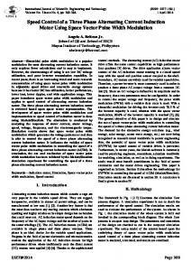
In spite of these limitations about 80% motors in the industries are induction motors. Hence, there is great importance to improve the reliability of induction motors under different operating conditions. For this purpose induction motor parameters play an important role.The three phase induction motor schematic diagram is shown in Fig. 1.
Fig. 1 Induction motor 1.2 Constructional Features of Induction Motor An induction motor has mainly the following parts i. A stationary stator
1
It is consisting of a steel frame, stator core, stator windings and a connection box as shown in Fig. 2. The steel frame of stator that supports a hollow, cylindrical core known as yoke. The stator core constructed from stacked laminations and having a number of evenly spaced slots which provide the space for the stator winding.
Fig. 2 Stator of Induction Motor ii. A revolving rotor The induction motor rotor is consisting of laminated core, rotor windings, shaft, slip rings in case of wound rotor induction motors as shown in Fig. 3. The rotor core is composed of punched laminations which are stacked to create a series of rotor slots and provide space for the rotor winding. There are two types of rotor windings, namely: a. Conventional 3-phase windings made of insulated wire (wound-rotor) similar to the winding on the stator. Usually Y-connected, the ends of the three rotor wires are connected to 3 slip rings on the rotor shaft. Hence, the rotor circuit is accessible. b. Aluminum rotor bars shorted together at the ends by two aluminum end rings, forming a squirrel-cage shaped rotor (squirrel-cage)
(a) Squirrel cage rotor
(b) Slip ring induction motor
Fig. 3 Different types of rotor of induction motor. iii. Bearings- A bearing is a mechanical element that permits relative motion between the parts, such as the shaft and the housing having minimum friction. 2
iv. Cooling Fan- All rotating electrical machines generate heat as a result of the electrical and mechanical losses inside the machine. Losses are high during starting, overload or dynamic braking. Cooling is necessary to continuously transfer the heat to a cooling medium, such as the air. For AC induction motors, cooling air is usually internally circulated and externally by one or more fans mounted on the rotor shaft. The most common type of AC motor is the totally enclosed fan cooled motor which is provided with a forced external cooling fan mounted on the non-drive end (NDE) of the shaft with cooling ribs that run axially along the outer surface of the motor frame. The fans are designed that keep the air flow close to the surface of the motor along entire length and improve self-cleaning and cooling of the ribs. An airgap is left between the fan cover and the ribs usually. 1.3 Principle of operation of Induction Motor The induction motor works on the principle of induction. When a three phase supply is given to a balanced three phase stator windings, which are uniformly distributed in space and mechanically displaced by 1200, produces a constant amplitude rotating magnetic field known as stator rotating MMF(Fs) as shown in Fig. 4. This rotating magnetic field rotates with the speed known as synchronous speed (Ns), mathematically written in terms of frequency and number of stator poles as: rpm This rotating magnetic field cuts the rotor windings and produces an induced voltage in the windings of rotor. As the rotor windings are short circuited, for both wound-rotor and squirrel cage, and induced current flows in the windings of rotor. Another magnetic field is produced by the rotor current called rotor MMF (Fr). A torque is produced as a result of the interaction of those two magnetic fields (i.e. stator MMF and Rotor MMF):
Where Tm is the motor torque and Fr and FS are the MMFs of the rotor and the stator respectively.
3
Fb
A
Fc
B‘
C‘
Fa B
A‘ (a) Winding of A- Phase
C (c) Winding of C- Phase
(b) Winding of B- Phase
Fs
Fb
Fc Fc
Fb
Fs
Fs Fc
Fb θ = 00
0
0
θ = 90
θ = 180
Fc
Fc
Fb
Fs Fb
Fs 0
θ = 270
θ = 360
0
Fig. 4 Stator rotating MMF at different angles
Torque Production In an induction motor the conventional 3-phase winding sets up the rotating magnetic field (Fs) and the rotor carries the current carrying conductors. An EMF and hence current is induced in the rotor due to the slip speed (i.e. difference between the Fs and the rotor). This induced rotor current produces a torque. As the slip speed reduced the torque produced also reduced. However, this slip speed cannot become zero because that would stop generation of the torque producing current itself. Therefore, induction motor can never run at synchronous speed and hence, it is called asynchronous motor. The parameter slip ‗s‘ is a measure of this relative speed difference (slip speed) s
ns n ns
s
ns
s 4
120 f1 ; p Number of poles p
where ns, s, f1 are the speeds of the Fs in rad/sec and RPM and n, are the speeds of the rotor in RPM and rad./sec respectively. The slip frequency and the angular slip frequency at which voltage is induced in the rotor is given by
Where nslip= slip speed ns= speed of the magnetic field n = rotor speed of the motor
1.4
Equivalent Circuit of Induction motor The induction motor acts like the transformer with the exception that its secondary windings are free to rotate.
Fig. 5 Equivalent Circuit of Induction Motor Where XR & RR are rotor reactance & rotor resistance. The same is true for the frequency, i.e. fr=s* fs It is known that
so, as the frequency of the induced voltage in the rotor
changes, the rotor circuit reactance also changes XR= 2πfrLr=2πsfeLr= s * XR0 Where XR0 is rotor reactance at the supply frequency (at blocked rotor) Then, we can draw the rotor equivalent circuit as follows
Fig. 6 Rotor Equivalent circuit 5
Where ER is the rotor induced voltage and RR is the rotor resistance Now the rotor current can be calculated
IR
ER ( RR jX R ) sER 0 ( RR jsX R 0 )
The numerator and denominator are divided by s so nothing changes we get (
)
Where ER0 is the induced voltage and XR0 is reactance of rotor at blocked rotor condition (s = 1) Now the rotor equivalent circuit may be redrawn as shown in Fig. 7.
Fig. 7 Modified rotor equivalent circuit
If we can combine the stator and rotor equivalent circuits in one equivalent circuit as shown in Fig. 8. Where 2 X 2 aeff X R0 2 R2 aeff RR
I2
IR aeff
E1 aeff ER 0 aeff
1.5
NS NR
Fig. 8
Determination of Induction-Motor Parameters i. DC Test of determination of stator resistance Connect any two stator leads to a variable-voltage DC power supply.Power supply is adjusted to provide rated stator current. Then determine the resistance from the applied voltage VDC and stator current IDC as follows.
6
a. For a Y-Connected Stator Stator resistance of each phase R1Y=RDC/2 b. For a Delta-Connected Stator
&
=1.5
ii. Blocked-Rotor Test
From the DC test, determine R2 when combined with data. The rotor is blocked so that it will not turn.A variable-voltage AC supply is connected and adjust the supply voltage until the blocked-rotor current is equal to the rated current. Neglect the exciting current under blocked-rotor conditions to remove the shunt parameters of equivalent circuit. Finally determine X1 and X2.
iii. No-Load Test
The rotor is allowed to run freely under no-load condition at rated voltage and rated frequency. At no-load condition, the speed is very close to synchronous speed and the slip =0, causing the current in R2/s to be very small, and will be ignored in the calculations. Determine the magnetizing reactance, XM and friction, combined core and windage losses. All the above mentioned parameters of induction motor is calculated under static conditions, but when motor operates these parameters changes dynamically predicting the motor condition.
7
1.6
Literature Review The induction motors are exposed to a wide variety of environments and conditions.
These factors, coupled with the aging process of any machine, make the motor subject to faults. These faults, if undetected is left, contribute to the degradation and eventual failure of the motors. Many methods and schemes are developed for parameter estimation of large induction motors, but these are generally not applied in smaller machines due to limitations related to sensing-device size and economic considerations. The induction motor parameter estimation is the art and science of building mathematical models of dynamic systems from observed input-output data. It can be seen as the interface between the real world of applications and the mathematical world of control theory and model abstractions [LJU 08]. The knowledge of all the machine parameters is very important to tune the controllers of a high performance motor drive system [VEL 89, HOL 91, STE 94, BOR 94, RIB 97]. The accurate knowledge of the induction motor parameters is critical for the sensorless drive strategies based on the stator flux estimation [HOL 01]. This fact has stimulated the development of specific techniques to determine the induction motor parameter [RIB 97], [HAB 93, BLA 95, KER 96, UMA 95, JAC 00]. The problems of estimating the parameters and states of a motor have been attacked from a variety of different perspectives summarised by various researchers [LAN 86, VEL 88,LN 89]. A variety of online and off-line methods have been proposed for determining the parameters of an induction motor rotor [HIL 84]. There are various techniques to estimate the induction motor parameters, such as: 1.
Conventional techniques
2.
Soft computing techniques a.
Fuzzy system
b.
Artificial neural network
c.
Genetic Algorithms
d.
PSO
e.
Integration of above techniques
8
1.6.1 Conventional methods There are various conventional methods available with their merits and demerits [PON 07, SIN03, BEL 08, ILO 05, TAL 07, BEN 00]. There are many ways to detect mechanical and electrical problems in induction motors, either directly or indirectly, such as motor current signature analysis [JUN 06, THO 01], line neutral voltage signature [KHE 09], instantaneous reactive power signature [DRI 09], stator current and motor efficiency [FRO 10], electromagnetic field monitoring [THO 93, ROM 10], chemical analysis, temperature measurement [FIL 94], infrared measurement, acoustic noise analysis [LEE 94], partial discharge measurement [OKU 07] and vibration monitoring [SCH 04, BEL 06, SAD 07], and fault detection based on parameter adaptation [BAR 09]. Dynamic performance of induction motor field-oriented controllers strongly depends on model parameter accuracy. A parameter mismatch produces an error in field orientation and undesirable coupling between the flux and torque controllers. Although it is possible to determine in advance the model parameters, significant changes may take place during the normal operation which has to be compensated online. In addition, several algorithms have been proposed to estimate the rotor speed (direct field-oriented control) [ZAM 98, SCH 92, KIM 94] or the rotor resistance (indirect field-oriented control) [GAR 97, ATK 96, STE 94] from an electromagnetic model and using only stator voltage and current measurements. Since the motor models used for estimation contain other machine parameters, the robustness of these algorithms can be improved if the errors or changes in model parameters are compensated online. Clearly, these parameters must be estimated independently of rotor speed and rotor resistance. The Knowledge of all the machine parameters is very important to tune the controllers of a high performance motor drive system [VEL 89, HOL 91, STE 94, BOR 94, RIB 97]. In particular, the value of the stator resistance is very important for some induction motor drive control strategies [DON 88, ROW 91, BOS 95]. The accurate knowledge of the stator resistance is critical for the sensorless drive strategies based on the stator flux estimation [HOL 01]. This fact has stimulated the development of specific techniques to determine the stator resistance [RIB 97] & [HAB 93, BLA 95, KER 96, UMA 95, JAC 00]. For several decades, the Kalman filter has proved to be a powerful tool for state and parameter estimation of linear and nonlinear systems and has been applied in various fields such as robotics [MAR 05], thermodynamics [CHA 04], medicine [BOR 04] or electrical engineering [BOL 03, MAC 06]. Applied to induction motors, it was proposed for estimation 9
of flux [CAV 89, ATK 91, SAL 93] and parameters [WAN 07, CAV 89, ATK 91, ZAI 92, WAD 97]. In addition, many studies have focused on diagnosis; among the proposed methods, some are based on state or parameter estimation [SED 98, DUR 99, SAI 00]. Induction-Motor Parameters vary significantly with operating conditions. Besides, the load torque can vary from no load to full load and stator (Rs) and rotor (Rr) resistances change with temperature and frequency, while inductances tend to saturate at high current levels. The effects of parameter and model uncertainties become even more relevant with speed sensorless control, calling for sophisticated methods for the estimation of flux and velocity. The benefits of sensorless control are the increased reliability of the overall system with the removal of mechanical sensors, thereby reducing sensor noise and drift effects as well as cost and size. However, to exploit the benefits of sensorless control, the developed estimation methods must achieve robustness against parameter and model uncertainties over a wide speed range. Parameters of particular concern in the sensorless control literature are the frequency-dependent Rr, temperature-dependent Rs, and the estimation of flux and velocity [BAR 08]. Nowadays, field-oriented control of induction motor electrical drives is widely used when high motor performances are required. However, performance is greatly affected by parameter uncertainty so as the behaviour of both controller and estimator, designed using a model-based approach, rapidly deteriorates in the presence of these uncertainties. Obviously, the behaviour of the whole control system is particularly sensitive to that of the state estimator. To cope with these uncertainties, on-line parameter identification, adaptive or robust design techniques, can be employed for designing either the estimator or the controller, or both [ALO 13]. Induction motor parameters change with temperature, frequency and saturation. The consequence of any mismatch between the parameter values used in the controller and those in the motor is that the actual rotor flux position does not coincide with the position assumed by the controller. The situation is illustrated in Fig. 9 given below [LEV 99]. This means that the actual rotor flux contains both d – and q -axis component, leading to a loss of decoupled flux and torque control. Performance of the drive therefore deteriorates from the desired. In order to avoid such a situation, it is necessary to provide the vector controller with accurate induction motor parameter values. These parameters have to be obtained somehow from measurements, during initialization of the drive. Since any vector controlled induction motor drive is inverter fed, numerous tests based on an inverter supply have been developed in recent past for determination of the required parameter values [LEV 99, VAS 98, LOR 97] Such methods are called ―offline parameter identification methods.‖ In addition, numerous 10
possibilities exist nowadays to update the parameter values during operation [KAZ 94, LEV 99, VAS 98, LOR 97]. The techniques that enable parameter adaptation during operation are termed as ―online parameter estimation methods.‖
Fig. 9 Rotor Flux Position [LEV 99].
The parameters that may need to be identified offline or tracked online depend on the vector control scheme under consideration [LEV 95]. The most important offline identification and online parameter estimation techniques are reviewed. 1.6.1.1 Offline Parameter Identification Techniques It is often the case in practice that one manufacturer supplies the inverter with a vector controller, while the machine comes from another manufacturer. It is then not possible to set the parameters of the controller in advance and these have to be set onsite, once when the inverter is connected to the machine. Such a situation has led to the development of the socalled self-commissioning procedures for vector controlled induction machines. The main idea behind this concept is that the controller automatically determines all of the parameters of an induction machine, required for vector control. The automated procedure of testing and calculation is done following the first enabling of the controller. As the induction machine may already be coupled to a load, the tests aimed at self-commissioning have to identify the required parameters at standstill. The identification is therefore performed with single-phase supply to the machine. In principle, two types of excitation may be applied—dc or ac. The one ideal for true self-commissioning is dc. From applied dc voltage and resulting dc steady state current, one finds the value of the stator resistance. Determination of the remaining parameters is then based most frequently on transient current response that follows application of the dc voltage. Self-commissioning schemes that rely on this approach are those described in [RUF 94, KHA91, KWO 94, GLO 98]. The methods regarded as suitable for commissioning but inappropriate for self-commissioning are those that either require some special conditions to be satisfied during the commissioning (for example, the machine is allowed to rotate) or they require substantially more complicated mathematical processing of the measurement results, when compared to the self-commissioning methods. For
11
example, procedures described in [CHR 96, MOO 94, RUF 93] are all based on some tests with single-phase supply to the machine. However, the method described in [CHR 96] involves application of pseudo-random binary-sequence voltage excitation and requires an adaptive observer. The procedure of [MOO 94] relies on maximum likelihood method to obtain transfer function parameters. A step voltage is applied at the stator terminals and the stator voltage and stator current responses are recorded. The Laplace transformation is used to get the transfer function along with the maximum likelihood estimation. The method of [RUF 93] requires application of the recursive least squares algorithm, this being the same as for the procedure of [CON 87]. The second possible excitation for parameter identification at standstill is single-phase ac. Standstill frequency response test forms in this case the basis for the parameter identification [BUN 93, KLA 91, BUN 95, KER 95]. A particularly interesting procedure based on single-phase ac excitation is the rotor time constant identification method of [WAN 88]. It is based on trial- error and essentially does not require any computations. Some of the offline identification procedures surveyed so far enables identification of the machine‘s magnetizing curve in addition to other rated parameter values. Such is the case for the methods described in [RUF 94, KWO 94, BUN 93, KLA 91, BUN 95]. It should be noted that the requirement for magnetizing curve identification often adds to the complexity of the commissioning procedure since more than one test needs to be performed. A significant step forward in this sense is the method of [BER 01], where magnetizing curve is identified at standstill using only one test with single phase ac supply. Other possibilities of the magnetizing curve identification for self-commissioning purposes have been explored in [RUF 96, RAS 96, BER 97]. If the conditions of the commissioning are less stringent, the drive may be allowed to rotate for the purposes of parameter identification. A whole array of additional parameter determination methods opens up in this case. For example, an extremely simple procedure for rotor time constant tuning [LOR 85] is based on the tests performed while the machine is rotating. The drive is operated in the torque mode for the purposes of the rotor time constant tuning, with rated rotor flux reference. An alternating square-wave torque reference is applied at certain speed of rotation. If the rotor time constant value used in the controller is correct, the actual torque is an alternating square-wave as well, so that the speed response follows a triangular function. If the rotor time constant setting is not correct, then the actual torque response is not the same as the torque reference. Speed response then deviates from triangular. Standard no-load test and locked rotor test may be performed with a PWM inverter supply if the commissioning situation allows for such testing. Parameters that are calculated are the same as those obtained with sinusoidal supply, provided that the calculations are 12
based on the fundamental components [BOG 93]. This feature is exploited in [LIN 96], where the parameters are identified using the dc, no-load and the pseudo-locked rotor tests. A method for pseudo-locked rotor test is presented since the mechanical locking of the rotor is undesirable in any onsite commissioning scenario. Identification of the machine‘s magnetizing curve becomes a simple and straightforward task if the machine is allowed to rotate under no-load conditions during the onsite commissioning. By defining the magnetizing curve‘s analytical approximation in a suitable functional form and by performing a series of steady state fundamental harmonic voltage measurements in the field weakening region, it becomes possible to determine the correct magnetizing curve approximation purely by visual inspection of the measurement results [LEV 00]. An experimental illustration of this method is given, where measured line-to-line fundamental voltage component is shown, together with the reconstructed magnetizing curve. Another magnetizing curve identification procedure is described in [LEV 99]. It relies on the signals that are already present within the drive controller (stator currents and the dc link voltage), so that additional measurements are not required. A special identification function, proposed in [LEV 99], ensures precise acquisition of the magnetizing curve, robust against the stator resistance variation, and the inverter lock-out time. The algorithm does not require any test signals. It is sufficient to perform the measurements during running of the unloaded motor at around 100 r/min. Performing measurements at such a low speed enables the impact of iron and mechanical losses on identification accuracy to be minimized. This, in turn, enables accurate identification down to 10% of the rated magnetizing flux, including the point of infliction. An illustration of the results of the procedure of [LEV 99] is given. Some other approaches to the magnetizing curve identification, described in [LEV 92, GAN 98, STA 97] are more involved and therefore less suitable for onsite commissioning of the drive. Method of [LEV 92] performs identification at standstill and only current measurements are needed. However, all the three phases of the machine are energized and standstill condition is achieved by means of closed loop speed control. The method requires that the vector controlled induction motor is coupled to a controllable load and is therefore not suitable for onsite commissioning. Similar conclusion applies to the broad-band excitation method [GAN 98], which requires injection of multiple frequency supply into the machine‘s stator terminals. Method of [STA 97], although apparently very accurate, is rarely applicable in practice since it requires that the neutral point of the stator star connected winding is accessible. It is worth noting that offline magnetizing curve (or magnetizing inductance) identification suffices for saturation compensation schemes and that identification of dynamic 13
(differential) inductance is usually not required. However, there are methods that enable identification of the dynamic inductance as well, for example [GAN 98] and [STA 94]. Compensation of iron losses in vector controlled induction machines usually requires knowledge of the equivalent iron loss resistance for the fundamental harmonic, which is a function of the fundamental frequency [LEV 95]. The equivalent iron loss resistance can be identified during the drive commissioning using the procedure outlined in [LEV 96]. A series of no-load tests are performed at various fundamental frequencies, using the same PWM voltage source inverter that will be subsequently used for the normal drive operation. Fundamental harmonic input power needs to be measured, mechanical losses are separated from the fundamental iron losses using the customary no-load test procedure, and equivalent iron loss resistance is eventually calculated. The procedure requires that rotation is permitted and that no-load condition is available. An illustration of the experimental results related to fundamental iron loss component and the corresponding equivalent iron loss resistance is given. Tests at standstill, which would enable identification of the equivalent iron loss resistance, do not seem to exist at present. It should be noted that accuracy of parameter determination in all offline identification techniques depends on the sample rate selection, quantization errors, resolution and accuracy of sensors, etc. [BOR 95]. Identified parameter values will therefore always be characterized with certain error margin. The major problem encountered in offline parameter identification at standstill is undoubtedly the inverter lockout time and nonlinearity, which make the accurate parameter determination on the basis of reconstructed voltages very difficult without prior knowledge of the inverter voltage drop characteristics [BUJ 95]. A technique for overcoming this problem has recently been proposed , based on recursive least squares [BER 97]. Further important works describing various approaches to self-commissioning and commissioning are those of [GAS 99, KUD 97, CHO 99, GOD 99, BAR 99, KAR 97, RIB 00, SEO 01]. 1.6.1.2 Online Rotor Time Constant Estimation Techniques The major effort has been put into development of rotor time constant (rotor resistance) online estimation methods. Due to a huge number of proposed solutions of very different nature, these are further classified into four subgroups. A. Spectral Analysis Techniques This group of methods encompasses all of the cases where online identification is based on the measured response to a deliberately injected test signal or an existing characteristic harmonic in the voltage/current spectrum [MAT 85, TOL 93, CHA 92, GAB 82, SUG 87, SAI 89, CER 95, TUN 94]. Stator currents and/or voltages of the motor are
14
sampled and the parameters are derived from the spectral analysis of these samples. In spectral analysis, a perturbation signal is used because under no-load conditions of the induction motor, the rotor induced currents and voltages become zero, so slip frequency becomes zero, and hence, the rotor parameters cannot be estimated. In [MAT 85] and [TOL 93], the disturbance to the system is provided by injecting negative sequence components. An online technique for determining value of the rotor resistance by detecting the negative sequence voltage is proposed in [MAT 85]. Special precautions need to be taken to circumvent the torque-producing action when an induction motor, equipped with this system, is used as a torque drive; otherwise, the outer loop might prevent the perturbation from being injected into the system. The main drawback of this method is that the strong second harmonic torque pulsation is induced due to the interaction of positive and negative rotating components of MMF. In [TOL 93], an online estimation technique is proposed, based on the d –q model in the frequency domain. The q-axis component of the injected negative sequence component is kept at zero, so that the machine torque is undisturbed. The d-axis component affects the flux of the machine. FFT is used to analyze the currents and voltages and the fundamental components of the sampled spectral values are used to determine the parameters. Average speed is used for the identification of parameters [TOL 93]. In [CHA 92], an attempt to create online tests similar to the no-load and full-load tests is made. In [GAB 82], a pseudo-random binary sequence signal is used for perturbation of the system by injecting it into the d-axis and correlating with q-axis stator current response. The sign of correlation gives the direction for rotor time constant updating. This method however does not work satisfactorily under light loads. In [SUG 87], a sinusoidal perturbation is injected into the flux producing stator current component channel. Though rotor resistance can be estimated under any load and speed condition, the cost is high due to the installation of two flux search coils. Solutions described in [SAI 89, CER 95, TUN 94] all along to the same category. A very different approach is the one described in [CIL 98, BEG 95, BEG 94] where rotor slot harmonics in stator current are tracked and used for online updating of the rotor time constant. B. Observer-Based Techniques In [LOR 93], Loron and Laliberté describe the motor model and the development and tuning of an extended Kalman filter (EKF) for parameter estimation during normal operating conditions without introducing any test signals. The proposed method requires terminal and rotor speed measurements and is useful for auto tuning an indirect field-oriented controller or an adaptive direct field-oriented controller. In [ZAI 92], Zai, DeMarco, and Lipo propose a method for detection of the inverse rotor time constant using the EKF by treating the rotor 15
time constant as the state variable along with the stator and rotor currents. This is similar to a previously mentioned method that injected perturbation in the system, except that in this case, the perturbation is not provided externally. Instead, the wide-band harmonics contained in a PWM inverter output voltage serve as an excitation. This method works on the assumption that when the motor speed changes, the machine model becomes a two-input/two output time-varying system with superimposed noise input. The drawbacks are that this method assumes that all other parameters are known and the variation in the magnetizing inductance can introduce large errors into the rotor time constant estimation. The application of the EKF for slip calculation for tuning an indirect field oriented drive is proposed in [FIN 98]. Using the property that in the steady state the Kalman gains are asymptotically constant for constant speeds, the Riccati difference equation is replaced by a look-up table that makes the system much simpler. The disadvantage is that, although the complexity of the Riccati equation is reduced, the full-order EKF is computationally very intensive as compared to the reduced order-based systems. In [KAT 93], an online estimation of rotor resistance and the magnetizing inductance, using continuous form of the Kalman filter is proposed, though the actual estimation is done offline using the discrete form of the KF. For using the KF online, it is important to estimate the magnetizing inductance accurately as an inaccurate magnetizing inductance gives improper value of the rotor time constant. The method is based on the assumption that since the value of the magnetizing inductance follows the motor flux level, the magnetizing inductance can be estimated along with the rotor resistance and the rotor time constant using the KF. Other solutions, based on the Kalman filter, are those described in [DEL 96, WAD 95, PEN 93, ATK 96, SOT 99]. An extended Luenberger observer (ELO) for joint state and parameter estimation was developed in [DUT 95, DUT 93]. In [DUT 95, DUT 93], the authors have provided a comparison of the operation of the ELO and the EKF. In [DUT 95], a deterministic approach to designing the ELO with joint online estimation of motor states and parameters is presented. In [DUT 93], Du and Brdys implemented the scheme using three different full-order ELOs. The first ELO was used for rotor time constant and rotor flux estimation. The second one was used for shaft speed and rotor flux estimation and the third for shaft speed, load torque, and rotor flux estimation. In the case of joint state and parameter estimation, ELO turns out to be the advantageous solution. Since the induction motor is a nonlinear system, the observations from the EKF at individual time instants do not lead to an overall optimal observation. For the ELO, there is a great deal of flexibility in choosing the gain, unlike the EKF and the rate of convergence can be tuned without adversely affecting the steady state accuracy of the observer. The main advantage of the ELO over the EKF is that 16
the observer performance can be greatly enhanced by simply adjusting the gain matrix for rapid convergence of the estimates, which gives an unbiased estimation in the case of the ELO. The major problems related to EKF and ELO applications are computational intensity and the fact that all the inductances are treated as constants in the motor equations. In order to improve the accuracy of the EKF-based rotor resistance identification, it is suggested in [ZAI 92, KAT 93, PEN 93] to simultaneously identify the magnetizing inductance. Another possibility of improving the accuracy is the inclusion of the iron loss into the model [WAD 95]. C. Model Reference Adaptive System-Based Techniques The third major group of online rotor resistance adaptation methods is based on principles of model reference adaptive control. This is the approach that has attracted most of the attention due to its relatively simple implementation requirements. The basic idea is that one quantity can be calculated in two different ways. The first value is calculated from references inside the control system. The second value is calculated from measured signals. One of the two values is independent of the rotor resistance (rotor time constant). The difference between the two is an error signal, whose existence is assigned entirely to the error in rotor resistance used in the control system. The error signal is used to drive an adaptive mechanism (PI controller) which provides correction of the rotor resistance. Any method that belongs to this group is based on utilization of the machine‘s model and its accuracy is therefore heavily dependent on the accuracy of the applied model. The number of methods that belong to this group is vast [GAR 80, AKA 82, KOY 85, KRI 85, LOE 85, LES 86, KAZ 86, OHN 86, DAL 87, OHM 89, LOR 90, ROW 91, SUM 93, VUK 93, KLA 94, TUN 94, UMA 94, GAN 95, GRI 97, WAI 99, KAN 99] and they primarily differ with respect to which quantity is selected for adaptation purposes. Reactive power-based method is not dependent on stator resistance at all and is probably the most frequently applied approach [GAR 80, KOY 85, KRI 85, ROW 91, SUM 93, GRI 97]. A method based on special criterion function, derived again from stator voltage and current measurement, is described in [VUK 93]. Next, air gap power can be selected as the quantity on which adaptation is based [DAL 87, OHM 89]. The reference air gap power is calculated from reference torque and frequency values, while the actual one has to be calculated from measured input power and estimated stator losses in the machine. Alternatively, dc link power can be measured instead of the machine‘s input power. In both cases, the accuracy of the method is heavily undermined by the need to estimate stator loss (and inverter losses if dc link power is measured). Other possibilities include selection of torque [ROW91, LOR 90], rotor back emf [LES 86, KAZ 86], rotor flux magnitude [ROW 91], rotor flux d-, and q-components [GAN 17
95], stored magnetic energy [TUN 94], product of stator q-axis current and rotor flux [UMA 94], stator fundamental rms voltage [LOE 85], stator d-axis or q -axis voltage components [UMA 94], or stator q-axis current component [AKA 82]. There are a couple of common features that all of the methods of this group share. First, rotor resistance adaptation is usually operational in steady-states only and is then disabled during transients. Thus, the adaptation can be based on steady-state model of the machine. Second, in the vast majority of cases, stator voltages are required for calculation of the adaptive quantity and they have either to be measured or reconstructed from the inverter firing signals and measured dc link voltage. Third, in most cases, identification does not work at zero speed and at zero load torque. Finally, identification heavily relies on the model of the machine, in which, most frequently, all of the other parameters are treated as constants. This is at the same time the major drawback of this group of methods. Indeed, an analysis of the parameter variation influence on accuracy of rotor resistance adaptation [KRI 86] shows that when rotor flux magnitude method is applied and actual leakage inductances deviate by 40% from the values used in the adaptation, rotor resistance is estimated with such an error that the response of the drive becomes worse than with no adaptation at all. Similar study, with very much the same conclusions, is described in [DIT 94] where parameter sensitivity is examined for d-axis stator voltage method, q-axis stator voltage method, air gap power method, and reactive power method. Due to high sensitivity of the model-based methods to other parameter variation effects, it is desirable to account for at least some of these in the process of rotor resistance adaptation. Variation of the magnetizing inductance with saturation is for this reason sometimes taken into account, so that the accuracy of rotor resistance identification is improved [SIV 86, SUL 89, SUM 93, VUK 93]. The other drawback of this group of methods, impossibility of adaptation at zero speed and zero load torque is successfully eliminated in certain cases. For example, the schemes of [AKA 82, VUK 93] are operational at zero speed and at light loads although they do fail at zero load. Operation of a MRAS rotor resistance adaptation scheme is illustrated by means of experimentally recorded traces. The method based on special criterion function of [VUK 93], which enables rotor resistance adaptation at zero speed and under light loading conditions, is implemented. The error function, which serves as the input into the PI controller, is shown together with the rotor resistance estimate in per unit (i.e., ratio of rotor resistance in the controller to the actual one in the machine). The drive operates at zero speed with 0.2 per unit load torque. The adaptation mechanism operation is illustrated for step variation of rotor resistance used in the controller, of 50. As can be seen, rotor resistance adaptation works well as the resistance in the controller always returns, after the introduced 18
disturbances, to the previous value (i.e., to=Rc/Rr=1 ). Other methods of online rotor resistance adaptation, that do not belong to any of the three main groups, are reviewed next. D. Other Methods There exist a number of other possibilities for online rotor resistance (rotor time constant) adaptation, such as those described in [CHA 90, BAR 99, TOL 99]. For example, the method of [TOL 99] does not require either a special test signal or complex computations. It is based on a special switching technique of the current regulated PWM inverter, which allows measurement of the induced voltage across the disconnected stator phase. The rotor time constant is then identified directly from this measured voltage and measured stator currents. The technique provides up to six windows within one electric cycle to update the rotor time constant, which is sufficient for all practical purposes. A simulation illustration of the method is given, where estimated and actual rotor time constant are shown. The updating is performed only twice (rather than six times) during one electrical cycle. Another possibility, opened up by the recent developments in the area of artificial intelligence (AI), is the application of artificial neural networks for the online rotor time constant (rotor resistance) adaptation. Such a possibility is explored in [MAY 98, YAN 94]. The other AI technique that can be utilized for online rotor time constant adaptation is the fuzzy logic [CER 97, TAC 98, ZID 01, BIM 01]. Recent emphasis on sensorless vector control has led to a development of a number of schemes for simultaneous rotor speed and rotor time constant online estimation, that are applicable in conjunction with the appropriate speed estimation model-based algorithms [KUB 94, LEE 96, HUR 96, ATT 97, KUB 98, AKA 99, AMB 99, AKA00, FAI 01]. These methods of rotor time constant estimation belong in vast majority of cases to one of the groups already reviewed in this section. An excellent review of the rotor resistance compensation schemes, available at the time, is the one of [KRI 91]. ONLINE ESTIMATION OF STATOR RESISTANCE An industrially accepted standard for sensored rotor flux oriented control has become the indirect rotor flux oriented control (IRFOC), which does not require the knowledge of the stator resistance. Since the rotor time constant is of crucial importance for decoupled flux and torque control in IRFOC, the major effort was directed toward development of online techniques for rotor time constant identification, as shown by the review in Online Rotor Time Constant Estimation Techniques. The situation has however dramatically changed with the advent of sensorless vector control, which requires rotor speed estimation. Vast majority of speed estimation techniques are based on the induction machine model and involve the stator resistance as a parameter in the process of speed estimation. An accurate value of the 19
stator resistance is of utmost importance in this case for correct operation of the speed estimator in the low speed region. If stator resistance is detuned, large speed estimation errors and even instability at very low speeds result. It is for this reason that online estimation of stator resistance has received considerable attention during the last decade, as witnessed by a large number of publications devoted to this subject [AKI 94, UMA 95, KER 95, CAB 97, ZHO 97, BOS 98, HAB 98, MIR 98, LEE 98, GUI 99, ZAM 99, MAR 00, LAI 00, TAJ 00, MIT 01, SHI 01, TSU 01, VAS 01]. The other driving force behind the increased interest in online stator estimation was the introduction of direct torque control (DTC), which in its basic form relies on estimation of stator flux from measured stator voltages and currents. The accuracy of DTC, especially in the low frequency region, therefore heavily depends on the knowledge of the correct stator resistance value. In general, methods of stator resistance estimation are similar to those utilized for rotor time constant (rotor resistance) estimation and include application of observers, extended Kalman filters, model reference adaptive systems, and artificial intelligence. In [FOR79, TAM 87] speed is estimated as a parameter of the induction machine model, given a priori knowledge of the machine electrical parameters. In [ABB 75, VEN 80, NAU 83, FOR 84], Steady-state slip using a variety of estimators is identified. Dynamic slip estimators were presented in [JOE 83, NAB 82]. A position estimator was described in [CUZ 90]. All of these methods assume knowledge of most or all of the electrical parameters. In [BEL 76, FIT 83, CON 87], off-line techniques for determining motor model parameters were presented. All of these methods require data in addition to knowledge of the stator electrical excitation and might even require disassembly of the machine. On-line parameter estimation techniques [IRI 84, KUB 85, CUZ 90, ATK 91, HUR 95] generally estimated a limited subset of the model parameters given knowledge of the remaining parameters. Many of these methods were focused on tracking the rotor resistance or time constant for field oriented control applications. Recursive estimation of both the model parameters and the mechanical state (rotor speed) using transient measurements was considered [SAN 85, VEL 88, MIN 89, VEL 89, VEL 92]. In these papers, induction motor problem was dealt in context with recursive estimation by assuming a separation of electrical and mechanical time constants and treating the mechanical slip as a parameter. Although the recursive estimation paradigm seemed promising because of difficulties like the sensitivity of the rotor resistance to temperature, these techniques required good a priori knowledge (better than 10% accuracy) of most of the parameters for successful performance. A common thread among these induction machine parameter and state estimation problems was the need for either a good 20
initial guess or accurate knowledge of machine parameters. The methods presented in this work, which are formally offline, could supplement many of the off- and on-line schemes above in practical engineering applications. For example, a controller designed around one of the on-line state estimators described above could, on installation with an unknown motor, apply a ―parameter acquisition‖ test using our methods to determine parameters or initial guesses required for the state estimator. 1.6.2 Soft Computing Techniques The soft Computing Techniques have been employed to assist the fault-detection task to correctly interpret the fault data, such as expert systems [FIL 00], fuzzy logic [SUL 07, ZID 08], fuzzy NN [BAL 07], artificial neural network (ANN) [CHO 91, DEM 02, KOW 03, YAN 04, AYH 06, SUH 07, MAR 07, BOU 08], wavelet transform technique [CHO 04, CUS 08, PON 09], and genetic algorithm [MAH 09]. 1.6.2.1 Fuzzy system for parameter identification A higher order fuzzy system identification method was given using subtractive clustering which was an extended application of subtractive clustering and a new powerful and flexible fuzzy algorithm for nonlinear dynamic system identification [DEM 00, SCH 01]. Use of linear parameter estimation techniques to determine the rotor resistance, self inductance of the rotor winding, as well as the stator leakage inductance of a three-phase induction machine was investigated [KOU 04]. To perform fault analysis on an induction motor using both experiments and simulation, and to study failure identification techniques applied for condition monitoring of the motor and finally to design an On-line condition monitoring system, fuzzy logic controller using Lab View was used [KUM 09]. A new two-step formulation for incipient fault detection in the stator windings of induction machines was given. The given methodology deals with the fault detection problem as a change point detection problem over the time series of the root mean square (rms) values of stator currents [HAS12]. During the operation of induction motor, stator resistance was changed incessantly with the temperature of the working machine. This situation might cause an error in rotor resistance estimation of the same magnitude and would produce an error between the actual and estimated motor torque which could lead to motor breakdown in worst cases. Therefore, Mohd Akmal Bin Rohani proposed an approach to estimate stator resistance of induction motor using fuzzy logic [ROH 10].
21
1.6.2.2 Artificial Neural Network technique Artificial Neural Network (ANN) is a system based on the operation of biological neural networks; it is an abstract simulation of a real nervous system. ANN‘s have been applied with astonishing success in fields ranging from Computer science to Engineering to Medicine. In recent years, the most stimulating and profitable development is increasing usage of ANN in various areas of electrical machines and control. ANN‘s attempts to model the structure of the human brain and are based on self-learning. It is composed of a large number of highly interconnected processing elements called neurons working in unison to solve a particular problem. The structure is highly parallel, resulting in ability to self organizes to represent information and rapidly solve problems in real life [SIL 06]. Generally, application of the ANN can be divided into the following categories: (i) Pattern recognition (ii) Grouping (iii) Association (iv) Control (v) Prediction (vi) Approximation of functions (vii) Optimization Neural networks theory has been an active research area in recent years. Due to the adaptive ability of a network‗s learning process, applying neural networks to dynamics system identification and control has become promising alternative to process control [YAM 91, KHA 91, FUK 92]. Two conventional approaches have been addressed in the neural network literature to cope with the adaptive control problem. First, some design parameters are learned off-line by measuring the input-output signals and observing the motor behaviour, in some key events. In the second approach, an adaptive leaning is implemented and the control input is determined on-line as the output of a neural network [ETX 94]. The Induction motor is a nonlinear multivariable dynamic system with parameters that vary with temperature, frequency, saturation, and operating point. Considering that induction motors are widely used in industrial applications, these parameters have a significant effect on the accuracy and efficiency of the motors and, ultimately, the overall system performance. Therefore, it is essential to develop algorithms for online parameter estimation of the induction motor. Such algorithms can be performed in real time because of the progress in the use of digital signal processors (DSPs) and microelectronics. The Luenberger observer system is implemented for flux estimation, and the speed observer system is utilized for 22
rotor-speed estimation. The rotor parameters are the most important parameters for the control of the induction motor drives. The rotor resistance can change up to 150% over the entire operation [TOL 03]. A number of methods that are both for the detection of the rotor parameter and the prevention of its variation have been discussed. In [LOS 84], the rotor parameter estimation is proposed by estimating the rotor temperature. This is based on the fact that the temperature influences the fundamental frequency component of the terminal voltage for a given input current. This is a tedious process because the temperature of the rotor windings has to be measured every time. Many papers have shown the effect of motor parameters on the quality of flux and speed estimation in vector control systems [KRZ 91, JAD 96, KAW 00, RAI 00, ORL 01, TOL 03].The online identification of the rotor resistance and mutual inductance are developed [WLA 08]. Artificial neural networks (ANNs) can be used to identify and control the nonlinear dynamic systems because they can approximate a wide range of nonlinear functions to any desired degree of accuracy. Moreover, they can be implemented in parallel and, therefore, shorter computational time can be achieved. In addition, they have immunity to harmonic ripples and have fault-tolerant capabilities. Since the 1990s, several investigations into the applications of neural networks in the field of electrical machines and power electronics have appeared [BOS 07]. In recent years, many papers have appeared which deal with the use of ANN in modulation systems [KAZ 94], in breakdown detection [RAI 00], in control [KUN 95, SIM 95, KUL00, PIN 01, KRZ 02, CIR 07, CIR 07], in the estimation of state variables [KUL00, ORL 01], and in the identification of induction-motor parameters [SIM 95, KAR 07]. In many papers [KRZ 91, BAL 00], the use of ANN has been tried for estimating the rotor angular speed. Among the methods used, it is possible to note two types of ANN designs. One is based on the machine model [BAL00], and the other one uses stator currents and voltages for direct speed estimation [ORL 01]. ANN has gained popularity over other techniques, as it is efficient in discovering similarities among large bodies of data. It is an effective alternative for performing motor fault detection while avoiding the need for a mathematical model. Because the ANN can adapt itself to learn arbitrarily complicated continuous nonlinear functions, it can learn the motor-incipient fault detection process, which enables it to give the accurate solution to a particular fault problem. In addition, the ANN can perform this function online through the use of inexpensive monitoring devices. These devices obtain the necessary measurements in a non invasive manner. The objective was to develop an alternative NN based fault-detection scheme that overcomes the limitations of the present schemes. It was observed that presented schemes were costly and applicable for large motors; furthermore many design parameters are 23
requested. In particular, concerning to long-time operating machines, these parameters cannot be available easily. In some existing schemes, either a detail mathematical model was required or many features had to be extracted, for which costly instrumentation was needed. In this scheme, only stator current was captured, and simple statistical parameters of current waveform were used as inputs to detect the four conditions of motor. As compared to existing schemes, the proposed scheme was simple, accurate, reliable, and economical. In most of the NN-based fault-detection schemes, a single network was used, whereas in the proposed scheme, a cascade connection of RBF–multilayer-perceptron (MLP) (RBF-MLP) network was developed to achieve a classification accuracy of 98.41%. For demonstration of cascade NN-based fault classifier, experimental results were used instead of simulation to make the classifier more practical. A new adaptive control scheme, composed of a neural identifier and a nonlinear controller, was applied to a linear induction motor [HAI 07, VIC 05]. 1.6.2.3 Integration of ANN & FS Prof. L.A. Zadeh proposed fuzzy logic as a model of a human thinking for nonlinear mapping of an input feature space into an output space [ZAD 65]. The artificial neural networks (ANNs) are another approach with large number of various architectures and learning strategies [LIP 87, HAY 94]. By combining these two approaches into a neuro-fuzzy model, it is possible to arrive at control structures with improved characteristics [LIN 96, JAN 97]. ANNs and fuzzy logic are widely used in the areas of modelling, identification, diagnostics and control of nonlinear systems. Two classes of ANNs that have received considerable attention in recent past are the feed-forward neural networks [NAR 90, NAR 96] and recurrent neural networks [KUC 95]. Research on fuzzy logic applications in control structure design shows a couple of general trends. The oldest one is based on heuristic knowledge and experience of a human expert with regard to the system behaviour [HAN 96]. More systematic approaches use procedure defined in deterministic manner [KUK 01], or various optimization methods, such as genetic algorithms [HOM 95], or simulated annealing [ISA 92]. The most promising approach encompasses numerous methods for self-organizing fuzzy model generation on the basis of given input-output numerical data [WAN 92, PAS 98]. The most successful realizations of the self-organizing fuzzy models are frequently obtained using clustering methods for partitioning the input-output space, combined with genetic algorithms(GA) [RUS 00], least-squares (LS) [BAR 98,SET 98], or gradient descentLS [JAN 93] optimization methods for model parameter adaptation. However, there are small numbers of methods that can provide true on-line adaptation process of a fuzzy model. One of rare examples is Neuro FAST, a Takagi–Sugeno–Kang fuzzy model, where the input space
24
is automatically partitioned using a modified fuzzy adaptive resonance theory mechanism [TZA 01]. In order for the required system performance to be maintained, it is a prerequisite that computationally efficient and accurate identification models are in existence [COC 89]. The vector control technique, which is developed upon the field orientation principle proposed by Haase in 1968 and Blaschke in 1970, decouples the flux and torque control in an IM [TRZ 94]. However, either fuzzy logic control or ANN has its own drawbacks, which cannot be avoided and neglected. A simple fuzzy controller implemented in the motor drive speed control has a narrow speed operation and needs much manual adjusting by trial and error if high performance is required [UDD 02]. On the other hand, it is extremely tough to create a training data for ANN that can handle all the operating modes [UDD 04]. A neurofuzzy controller (NFC) for the IM motor drive has the advantages of both FLC and ANN. Over the last decade, researchers reported works on the application of NFC for variable speed drives [CON 94, LIN 96, BOS 97, GRA 98, RUB 02, RAS 04, UDD 04]. However, the conventional NFCs utilized in earlier works have a large number of membership functions and rules. 1.6.2.4 Genetic algorithm (GA) There are many occasions where knowledge of motor parameters for system type studies are needed, albeit not at the level of accuracy needed for accurate efficiency determination for example. The source data for determination of such parameters is also often generic, such as torque data from a manufacturer describing a whole range of machines of a certain design. The equations relating the required motor parameters to the given data are often nonlinear in nature. Optimization techniques like the Newton-Raphson techniques have been applied to this type of problem with some success, although with the inherent problem of convergence to a local minimum instead of the global minimum. The optimum determined by the NewtonRaphson technique depends heavily on the initial guess of the parameter, with the possibility of a slightly different initial value causing the algorithm to converge to an entirely different solution. One important parameter required by the algorithm is the derivative of the function, which is not always available or may be difficult to calculate. These problems have encouraged the authors to investigate alternative techniques of solution. One of these is evolutionary algorithms. These methods encompass a broad class of algorithms, two of which are the genetic algorithm and the genetic programming techniques [RUD 94, GOL 89, DAV 91, MIT 96, REE 93, BLI 95, TEL 94, KOZ 96, KOZ 92, KOZ 94, MIC 92]. Possibilities of genetic algorithms application for parameters identification of induction motor was given by Edina Bajrektarević [BAJ 02]. The basic procedure to develop a genetic
25
algorithm was described and the examples of its application for parameter identification were introduced [MAR 02] In order to simplify the offline identification of induction motor parameters, a method based on optimization using a multi objective genetic algorithm was proposed by Tahir Sag and Mehmet Cunkas [SAG07]. The flux linkage model and torque model of an induction motor were adapted for the estimation [TRE10]. Estimation of parameters of three-phase induction motor in order to conduct on-site energy audits of existing motors was used to project a cost savings. This technique used only a few sets of data (voltage, current, speed, power factor or torque if possible) from the field test of motor (on-site), instead of the no load and blocked rotor tests, coupled with the genetic algorithm for evaluating the equivalent circuit parameters [PHU99]. 1.6.2.5 Particle swarm optimization(PSO) An efficient and reliable Particle Swarm based approach to Optimal Design of three-phase Induction Motor (ODIM) was proposed. The proposed approach employed a particle-swarmoptimization (PSO) technique to search for optimal values induction motor design parameters. The approach had been examined and tested [KAN07]. An adaptive system identification/parameter estimation algorithm for a three-phase cage induction motor based on particle swarm optimization (PSO) was given. The performance of the proposed algorithm was emphasized by comparing its results with those of the wellknown stochastic optimization techniques of genetic algorithm (GA) and simulated annealing (SA) for the benchmark application with unknown parameters to identify [NIK10]. Parameter identification of an induction machine is of great importance in numerous industrial applications, including the assessment of machine performance and design of control schemes. Typical parameter identification of induction machines has been described and Parameter identification is based on the input–output signals and the model used [TEL 03]. Over the past few decades, with the indirect field-oriented control and non sinusoidal measurements, most of the methods can be roughly divided into three categories: signal injection-based method [HOL 06, WUY 06, KWO 09, ZHA 09], model reference adaptive system-based technique [TEL 03, MAR 07, MAI 08], and optimization techniques [ABD 05, KAR 07, ORL 07, WLA 08, TRE 09]. The signal injection-based method is to improve the estimation of low speed performance of sensor less schemes or to excite the machine to create various response signals. They often require extra hardware for signal injection. Applications of signal injection have been presented in dealing with the stator and rotor winding temperatures [WUY 06].The model reference adaptive system uses the error between the estimated and the reference signals to calculate the parameters. In optimization
26
techniques, parameter estimation has been investigated by using the artificial intelligence including the particle swarm optimization (PSO) and the least squares strategy [CIR 05, DIN 10]. These techniques have been reported to minimize the consequences of parameter sensitivity in vector controlled drives. Many researchers have applied the inverter drive to control the exciting signals of the induction machine in the identifying process. Based on sinusoidal measurements, the voltage, current, active power, and rotor speed are used to identify the parameters of a large induction machine [BAB 07]. Laroche and Boutayeb [LAR 10] presented an original idea to estimate the parameters under the sinusoidal model. New identification methods were also developed for linear systems and can be extended to nonlinear systems. The hierarchical gradient identification method can estimate the parameters and states [DIN 09, DIN 10], the multiinnovation identification method has improved the convergence rate of gradient-based estimation, and both methods can be applied to non uniformly sampled systems [DIN 07, DIN 09, DIN 10]. Although many researchers have investigated the parameter identification of induction machines, little work has been seen doing a full enumeration of all parameters, including both the electrical and mechanical parameters. A method to identify all parameters of the induction machine with a no-load low-voltage starting test was proposed having simple structure without needing extra hardware, which could significantly simplify the procedures and save cost [LIN 12]. 1.6.2.6 Other Techniques Nowadays, a number of complex models were also available, often combining magnetic field theory with classic circuit approach which could now easily deal with once ―hard-to calculate‖ effects of induction machine, such as magnetic saturation, iron losses etc [DEM 06]. The induction machine parameters were typically obtained from no-load, rated load and short circuit (locked rotor) measurements [STI 04]. The drive was usually supplied with symmetrical three phase voltages that contained only first harmonic. Such measurements gave precise machine's parameters only for symmetric machines. In case of machine's electrical asymmetry due to the broken rotor bars [BON 92, TOL 95, YIN 09] the usual measurements did not give accurate machine parameters. Many already developed mathematical models of induction machine with broken rotor bars were complex as they model the internal states of induction machine in great detail either by using high number of differential equations [SIZ 09, CUN 05] or even by finite element analysis (FEA) [FIS 01, FAI 08] to correctly model the magnetic circuit of the machine. The parameters for these 27
kinds of models could only be obtained either analytically or by FEA simulations. Newly introduced simplified two axes model of induction machine with rotor fault [NEM 10], allowed us to obtain the parameters either via FEA or through measurements. On-line condition monitoring and diagnostic system of induction motor drives. It enabled a detection of broken rotor bars at an early stage of the fault propagation. The method was based on the analysis of stator current frequency spectrum, which could be measured without disturbing normal motor operation [FIS 08].Two advanced motor drive subsystems with improved controllers had been designed and developed for an HEV power train. The two subsystems were the starter-generator electric drive and the propulsion motor drive. The contribution of this research would enable efficient utilization of the HEV power train [HAS 08]. A new technique for directly designing a linear digital controller for a single-phase pulse width modulation (PWM) converter systems, based on closed-loop identification. The design procedure consists of three steps. First, obtain a digital current controller for the inner loop system by using the error space approach, so that the power factor of the supply was close to one [YOU 10]. Two methods based on Shuffled Frog Leaping Algorithm (SFLA) and Imperialistic Competitive Algorithm (ICA) for determining the values of the steady-state equivalent circuit parameters of an induction motor was given [MAR 11]. Three Phase Induction Motors Induction motors were the work horse of the modern industry. A dynamical model of a 3-Φ induction motor was developed with an aim of parameter identification [SAD 11].
1.7 Proposed Work It is understood from the literature survey that the parameters of induction motor may vary due to several factors such as: machine internal temperature, machine aging, magnetic saturation, the coupling effect between the internal system and external systems, and so forth. Thus, there is a need for an efficient and accurate parameter estimation technique for studies such as on-line analysis in which the operational model parameters may deviate substantially from their nominal values and affects the motor performance. The on-line measurement based approach has the advantage of the direct measurement of actual transient behaviors of induction motor and yields more accurate machine models. Further, since the motor model is intended to represent motor transient behaviors under certain system operating conditions, on-line measured data are very useful in deriving an accurate motor model. Evolution of soft computing techniques has encouraged the researchers to develop efficient algorithms and tools for parameter estimation. The basic outline of the proposed work is as follows: 28
To develop an efficient integrated approach using soft computing tools for parameter estimation of induction motor.
To evaluate model parameters of the induction motor using above developed approach.
To validate the results obtained by soft computing techniques by its hardware implementation and
Evaluation of model at different operating conditions.
The Various stages of the proposed work are given in Figure-10. Input
Induction motor
Physical Level
Output
Measurements
Preprocessing
Physical Laws and Priori Knowledge
Model structure determination
Soft Computing Tool
Parameter Estimation Evaluation of Model and its parameters
Abstract Level
Final model and its parameters Figure-10: Flow chart of proposed method
1.8 References [ABB 75]
Abbondanti A. and Brennen M., (1975), ―Variable speed induction motor drives use electronic slip calculator based on motor voltagesand currents‖, IEEE Trans. Ind. Applicat., vol. IA-11, pp. 483–488, Sept. /Oct.
[ABD 05]
Abdelhadi B., Benoudjit A., and Nait-Said N., (2005), ―Application of genetic algorithm with a novel adaptive scheme for the identification of induction machine parameters‖, IEEE Trans. Energy Convers., vol. 20, no. 2,pp. 284–291, Jun.
29
[AKA 00]
Akatsu Kan, and Kawamura Atsuo , (2000),” Online Rotor Resistance Estimation Using the Transient State Under the Speed Sensorless Control of Induction Motor”, IEEE Transactions On Power Electronics, Vol. 15, No. 3, May.
[AKA 82]
Akamatsu M., Ikeda K., Tomei H., and Yano S., (1982), ―High performance IM drive by coordinate control using a controlled current inverter‖, IEEE Trans. Ind. Applicat., vol. 18, pp. 382–392, July/Aug.
[AKA 99]
Akatsu K. and Kawamura A., (1999), ―Sensorless very low and zero speed estimations with on-line secondary resistance estimation of induction motor without adding any signal‖, Proc. IEEE Ind. Applicat. Soc. Annu. Meeting, pp. 187–193.
[AKI 94]
Akin E., Ertan H. B., and Uctug M. Y., (1994), ―A method for stator resistance measurement suitable for vector control‖, Proc. IEEE Ind. Electron. Soc. Annu. Meeting, pp. 2122-–2126.
[ALO 13]
Alonge Francesco , D‘Ippolito Filippo and Sferlazza Antonino , (2013),‖ Sensorless Control of Induction Motor Drive Based on Robust Kalman Filter and Adaptive Speed Estimation‖, Copyright (C) 2013 IEEE.
[AMB 99]
Ambrozic V., Nedeljkovic D., and Nastran J., (1999),
―Sensorless control of induction
machine with parameter adaptation‖, Proc. IEEE Int. Symp. Ind. Electron., pp. 724–728. [ATK 91]
Atkinson D.J., Acarney P., and Finch J., (1991), ―Observers for induction motor state and parameter estimation‖, IEEE Trans. Ind. Appl., vol. 27, no. 6, pp. 1119–1127, Dec.
[ATK 96]
Atkinson D, J., Finch J. W., and Acarnley P. P., (1996), ―Estimation of rotor resistance in induction motors‖, Proc. IEE—Elect. Power Applicat., vol. 143, no. 1, pp. 87–94, Jan.
[ATT 97]
Attaianese C., Tomasso G., Damiano A., Marongiu I., and Perfetto A., (1997), ―On line estimation of speed and parameters in induction motor drives‖, Proc. IEEE Int. Symp. Ind. Electron., pp. 1054–1059.
[ATT 98]
Attaianese Ciro, Damiano Alfonso, Gatto Gianluca , Marongiu, Ignazio and Perfetto Aldo, (1998), Induction Motor Drive Parameters Identification‖, IEEE Transactions On Power Electronics, Vol. 13, No. 6, November..
[AYH 06]
Ayhan B., Chow M. Y., and Song M. H., (2006), ―Multiple discriminant analysis and neuralnetwork-based monolith and partition fault-detection schemes for broken rotor bar in induction motors‖, IEEE Trans. Ind. Electron., vol. 53, no. 4, pp. 1298–1308, Jun.
[BAB 07]
Babau R.,
Boldea I., Miller T. J. E., and
Muntean N., (2007), ―Complete parameter
identification of large induction machines from no-load acceleration deceleration tests‖, IEEE Trans. Ind. Electron., vol. 54, no. 4, pp. 1962-1972, Aug. [BAJ 02]
Bajrektarević Edina, (2002), "Parameter Identification of Induction Motor Using a Genetic Algorithm".
[BAL 00]
Balara D. and Timko J., (2000), ―Identification of induction motor parameters with use of neural networks taking into account main flux saturation effect‖, Proc. 9th Int. Conf. EPEPEMC. Ko¢ sice, Slovak Republic, pp. 6.17–6.23.
30
[BAL 07]
Ballal M. S., Khan Z. J., Suryawanshi H. M., and Sonolikar R. L., (2007), ―Adaptive neural fuzzy inference system for the detection of inter-turn insulation and bearing wear faults in induction motor‖, IEEE Trans. Ind. Electron., vol. 54, no. 1, pp. 250–258, Feb.
[BAR 07]
Barut Murat , Bogosyan Seta and Gokasan Metin, (2007), ‖Speed-Sensorless Estimation for Induction Motors Using Extended Kalman Filters‖, IEEE Transactions On Industrial Electronics, Vol. 54, No. 1, February
[BAR 08]
Barut Murat , Bogosyan Seta, and Gokasan, Metin, (2008),‖ Experimental Evaluation of Braided EKF for Sensorless Control of Induction Motors‖, IEEE Transactions On Industrial Electronics, Vol. 55, No. 2, February.
[BAR 09]
Barrera P. M. de la, Bossio G. R., Garcia G. O., and Solsona J. A., (2009), ―Stator core fault diagnosis for induction motors based on parameters adaptation‖, Proc. IEEE SDEMPED, pp. 1–6.
[BAR 98]
Barada S. and Singh H., (1998),
―Generating optimal adaptive fuzzy-neural models of
dynamical systems with application to control‖, Trans. Syst., Man, Cybern. C, vol. 28, pp. 371–391, Aug. [BAR 99]
Ba-razzouk A., Cheriti A., and Rajagoplan V., (1999), ―Real time implementation of a rotor time-constant online estimation scheme‖, Proc. IEEE Ind. Electron. Soc. Annu. Meeting, pp. 927–932.
[BAR 99]
Barrero F., Perez J., Millan R., and Franquelo L. G., (1999), ―Self-commissioning for voltagereferenced voltage-fed vector controlled induction motor drives‖, Proc. IEEE Ind. Electron. Soc. Annu. Meeting, pp. 1033–1038.
[BAS 08]
Bastiaensen Cindy, Deprez Wim, Symens Wim, and Johan Driesen, (2008),‖ Parameter Sensitivity and Measurement Uncertainty Propagation in Torque-Estimation Algorithms forInduction Machines‖, IEEE Transactions On Instrumentation And Measurement, Vol. 57, No. 12, December.
[BEG 94]
Beguenane R., Ghyselen C., and Schoorens H., (1994), ―A proposed induction motor speed sensor without contact from slot harmonics. Application to rotoric time constant identification‖, Proc. Inst. Elect. Eng. Conf. Power Electron. Variable-Speed Drives, pp. 90– 95.
[BEG 95]
Beguenane R. and Capolino G. A., (1995), ―Induction motor rotor time constant measurement for vector control drives without rotary transducer‖, Proc. IEEE Int. Symp. Power Eng. Power Technol., vol. 3, pp.13–17.
[BEL 06]
Bellini A., Concari C., Franceschini G., Tassoni C., and Toscani A., (2006), ―Vibrations, currents and stray flux signals to assess induction motors rotor conditions‖, Proc. IECON, Nov., pp. 4963–4968.
[BEL 08]
Belatel Mimi, Benalla Hocine, (2008), ―A Multiobjective Design Optimization of Induction Machine using CAD and ANNs‖, ICGST-AIML Journal, ISSN: 1687-4846, Volume 8, Issue II, pp. 1-8, September.
31
[BEL 76]
Bellini A., Carli A. de and Cava M. L., (1976), ―Parameter identification for induction motor simulation‖, Automatica, vol. 12, no. 4, pp. 383–386, July.
[BEN 00]
Benbouzid M., (2000), ―A review of induction motors signature analysis as a medium for faults detection‖, IEEE Trans. Ind. Electron., vol. 47, no. 5, pp. 984–993, Oct.
[BER 01]
Bertoluzzo M., Buja G. S., and Menis R., (2001), ―Self-commissioning of RFO IM drives: One-test identification of the magnetization characteristic of the motor‖, IEEE Trans. Ind. Applicat., vol. 37, pp. 1801–1806, Nov./Dec.
[BER 97]
Bertoluzzo M., Buja G. S., and Menis R., (1997), ―Inverter voltage drop-free recursive leastsquares parameter identification of a PWM inverter-fed induction motor at standstill‖, in Proc. IEEE Int. Symp. Ind. Electron., 1997, pp. 649–654.
[BER 97]
Bertoluzzo M., Buja G., and Menis R., (1997), ―Identification techniques of induction motor parameters for self-commissioning field-oriented drives‖, Automatika, vol. 38, no. 3–4, pp. 103–115.
[BIM 01]
Bim E., (2001), ―Fuzzy optimization for rotor constant identification of an indirect FOC induction motor drive‖, IEEE Trans. Ind. Electron., vol. 48, pp. 1293–1295, Dec.
[BLA 95]
Blasco-Giménez R., Asher G. M., and Summer M., (1995), ―A new method of stator resistance estimation for enhanced dynamic performance of sensorless vector control drives‖, Proc. EPE Conf., pp. 1689–1694.
[BLI 95]
Blickle Tobias and Thiele Lothar, (1995), ―A Comparison of Selection Schemes used in Genetic Algorithms‖, TIK-Report No. 11, December, Computer Engineering and Communication Network Lab, Swiss Federal Institute of Technology, Switzerland
[BOG 07]
Boglietti A., Cavagnino A., and Lazzari M., (2007), ―Geometrical approach to induction motor design‖, Proc. IEEE IECON, Taipei, Taiwan, Nov. 5–8, pp. 149–156
[BOG 11]
Boglietti Aldo, Cavagnino Andrea, and Lazzari Mario, (2011),‖ Computational Algorithms for Induction-Motor Equivalent Circuit Parameter Determination—Part I:Resistances and Leakage Reactances‖, IEEE Transactions On Industrial Electronics, Vol. 58, No. 9, September.
[BOG 93]
Boglietti A., Ferraris P., Lazzari M., and Profumo F., (1993), ―Induction motor equivalent circuit parameters determination from standard tests made with inverter supply‖, in Proc. Inst. Elect. Eng. Elect. Mach. Drives Conf., pp. 271–276.
[BOL 03]
Bolognani S., Tubiana L., and Zigliotto M., (2003), ―Extended Kalman filter tuning in sensorless PMSM drives‖, IEEE Trans. Ind. Appl., vol. 39, no. 6, pp. 1741–1747, Dec.
[BON 92]
Bonnet A. H., Soukup G. C., (1992), "Cause and Analysis of Stator and Rotor Failures in Three-Phase Squirrel-Cage Induction Motors", IEEE Transactions on Industry Applications, vol. 28, n.4, pp.921-937.
32
[BOR 04]
Borella B., Lucchi E., Nicosia S., and Valigi P., (2004), ―A Kalman filtering approach to estimation of maximum ventricule elastance‖, presented at the Conf. IEEE EMBS, San Francisco, CA, Sep.
[BOR 94]
Borgard D. E.,Olsson G., and Lorenz R.D., (1994), ―Accuracy issues for parameter estimation of field oriented induction machine drives‖, Proc. IEEE-IAS Annu. Meeting, pp. 593–600.
[BOR 95]
Borgard D. E., Olsson G., and Lorenz R. D., (1995), ―Accuracy issues for parameter estimation of field oriented induction machine drives‖, IEEE Trans. Ind. Applicat., vol. 31, pp. 795–801, July/Aug.
[BOS 07]
Bose B. K., (2007), ―Neural network applications in power electronics and motor drives—An introduction and perspective‖, IEEE Trans. Ind. Electron., vol. 54, no. 1, pp. 14–33, Feb.
[BOS 95]
Bose B.K., Simoes M.G., Crecelius D., Rajashekara K., and Martin R., (1995), ―Speed sensorless hybrid vector controlled induction motor drive‖, Proc. IEEE-IAS Annu. Meeting, pp. 137–143.
[BOS 97]
Bose B. K., Patel N. R., and Rajashekara K., (1997), ―A neuro-fuzzy based online efficiency optimization control of a stator flux-oriented direct vector controlled induction motor drive‖, IEEE Trans. Ind. Electron., vol. 44, no. 2, pp. 270–273, Apr.
[BOS 98]
Bose B. K.and Patel N. R., (1998), ―Quazi-fuzzy estimation of stator resistance of induction motor‖, IEEE Trans. Power Electron., vol. 13, pp. 401–409, May.
[BOU 08]
Bouzid M. B. K., Champenois G., Bellaaj N. M., Signac L., and Jelassi K., (2008), ―An effective neural approach for the automatic location of stator interturn faults in induction motor‖, IEEE Trans. Ind. Electron, vol. 55, no. 12, pp. 4277–4289, Dec.
[BUJ 95]
Buja G. S., Menis R., and Valla M. I., (1995), ―MRAS identification of the induction motor parameters in PWM inverter drives at standstill‖, Proc. IEEE Ind. Electron. Soc. Annu. Meeting,pp. 1041—1041.
[BUN 93]
Bünte A. And Grotstollen H., (1993), ―Parameter identification of an inverter-fed induction motor at standstill with a correlation method‖,
Proc. Europe. Conf.
Power Electron.
Applicat., vol. 5, pp. 97–102. [BUN 95]
Bünte A.and Grotstollen H., (1995), ―Offline parameter identification of an inverter- fed induction motor at standstill‖, Proc. Europe. Conf. Power Electron. Applicat., pp. 3.492– 3.496.
[CAB 97]
Cabrera L. A., Elbuluk E., and Husain I., (1997), ―Tuning the stator resistance of induction motors using artificial neural network‖, IEEE Trans. Power Electron., vol. 12, pp. 779–787, Sept.
[CAS 05]
Castaldi Paolo and Tilli Andrea, (2005), ‖ Parameter Estimation of Induction Motor at Standstill With Magnetic Flux Monitoring‖, IEEE Transactions On Control Systems Technology, Vol. 13, No. 3, May
33
[CAV 89]
Cava M.L., Picardi C., and Ranieri F., (1989), ―Application of the extended Kalman filter to parameter and state estimation of induction motors‖, Int. J. Model. Simul., vol. 9, no. 3, pp. 85–89.
[CER 95]
Cerruto E., Consoli A., Raciti A., and Testa A., (1995), ―Slip gain tuning in indirect field oriented control drives‖, Electric Machines and Power Systems, vol. 23, pp. 63–79.
[CER 97]
Cerruto E., Consoli A., Raciti A., and Testa A., (1997), ―Fuzzy adaptive vector control of induction motor drives‖, IEEE Trans. Power Electron., vol. 12, no. 6, pp. 1028–1040, Nov.
[CHA 04]
Chauvin J., Corde G., Moulin P., Castagné M., Petit N., and Rouchon P., (2004), ―Real-time combustion torque estimation on a Diesel engine test bench using time-varying Kalman filtering‖, presented at the Conf. Decision and Control, Atlantis, Paradise Island, Bahamas.
[CHA 90]
Chan C. C. and Wang H., (1990), ―An effective method for rotor resistance identification for high-performance induction motor vector control‖, IEEE Trans. Ind. Electron., vol. 37, no. 6, pp. 477–482.
[CHA 92]
Chai H. and Acarnley P. P., (1992), ―Induction motor parameter estimation algorithm using spectral analysis‖, Proc. Inst. Elect. Eng., pt. B, vol. 139, no. 3, pp. 165–174.
[CHO 04]
Chow T. W. S. and Hai S., (2004), ―Induction machine fault diagnostic analysis with wavelet technique‖, IEEE Trans. Ind. Electron., vol. 51, no. 3, pp. 558–565, Jun.
[CHO 91]
Chow M. and Yee S. O., (1991), ―Application of neural networks to incipient fault detection in induction motors‖, J. Neural Netw. Comput., vol. 2, no. 3, pp. 26–32.
[CHO 99]
Choi H. S. and Sul S. K., (1999), ―Automatic commissioning for vector controlled ac motors using Walsh functions‖, Proc. IEEE Ind. Applicat. Soc. Annu. Meeting, pp. 1284–1289.
[CHR 96]
Chrzan P. J. and Klaassen H., (1996), ―Parameter identification of vector-controlled induction machines‖, Electrical Engineering, vol. 79, no. 1, pp. 39–46.
[CIL 98]
Cilia J., Asher G. M., Shuli J., Sumner M., Bradley K. J., and Ferrah A., (1998), ―The recursive maximum likelihood algorithm for tuning the rotor time constant in highperformance sensorless induction motor drives‖, Proc. Int. Conf. Elect. Mach., pp. 926–930.
[CIR 03]
Cirrincione Maurizio ,Pucci Marcello, Cirrincione Giansalvo, and Capolino Gérard-André, (2003), ―A New Experimental Application of Least-Squares Techniques for the Estimation of the Induction Motor Parameters”, IEEE Transactions On Industry Applications, Vol. 39, No. 5, September/October.
[CIR 05]
Cirrincione M., minimization for
Pucci M.,
Girrincione G., and
Capolino G.A., (2005), ―Constrained
parameter estimation of induction motors insaturated and unsaturated
conditions‖, IEEE Trans. Ind. Electron., vol. 52,no. 5, pp. 1391–1402, Oct. [CIR 07]
Cirricione M., Cirricione G., Pucci M., and Capolino G.-A., (2007), ―Sensorless control of induction machines by a new neural algorithm: The TLS EXIN neuron‖, IEEE Trans. Ind. Electron., vol. 54, no. 1, pp. 127–149, Feb.
34
[CIR 07]
Cirricione M., Cirricione G., Pucci M., and Capolino G.-A., (2007), ―Sensorless control of induction machines by a new neural algorithm: The TLS EXIN neuron‖, IEEE Trans. Ind. Electron., vol. 54, no. 1, pp. 150–165, Feb.
[COC 89]
Cochran P. L., (1989), Polyphase Induction Motors: Analysis, Design, and Applications. New York: Marcel Dekker.
[COM 09]
Comanescu Mihai, (2009),‖ An Induction-Motor Speed Estimator Based onIntegral SlidingMode Current Control‖, IEEE Transactions On Industrial Electronics, Vol. 56, No. 9, September.
[CON 87]
Consoli A., Fortuna L. and Gallo A., (1987), ―Induction motor identification by a microcomputer-based structure‖, IEEE Trans. Ind. Electron., vol. IE-34, pp. 422–428, Nov.
[CON 94]
Consoli A., Cerruto E., Raciti A., and Testa A., (1994), ―Adaptive vector control of induction motor drives based on a neuro-fuzzy approach‖, Proc. IEEE PESC, pp. 225–232.
[CUN 05]
Cunha C.C.M., Lyra R.O.C., Filho B.C., (2005),
―Simulation and analysis of induction
machines with rotor asymmetries", IEEE Transactions on Industry Applications, 41, No. 1, pp. 18-24. [CUS 08]
Cusido, L. Romeral, J. A. Ortega, J. A. Rosero, and A. Garcia Espinosa, (2008), ―Fault detection in induction machines using power spectral density in wavelet decomposition‖, IEEE Trans. Ind. Electron., vol. 55, no. 2, pp. 633–643, Feb.
[CUZ 90]
Cuzner R., Lorenz R., and Novotny D., (1990), ―Application of nonlinear observers for rotor position detection on an induction motor using machine voltages and currents‖, Conf. Rec IEEE-IAS Annu. Meeting, pp. 416–421.
[DAL 87]
Dalal D. And Krishnan R., (1987), ―Parameter compensation of indirect vector controlled induction motor drive using estimated air gap power‖, Proc. IEEE Ind. Applicat. Soc. Annu. Meeting, pp. 170–176.
[DAV 91]
Davis Lawrence,Van Nostrand Rein- hold, NY, (1991) , Handbook of Generic Algorithms
[DEL 96]
Dell‘Aquila A., Papa S., Salvatore L., and Stasi S., (1996), ―A delayed state Kalman filter for online estimation of induction motor parameters and rotor flux space vector position‖, Proc. IEEE Mediterranean Electrotech. Conf., vol. 1, pp. 269–273.
[DEM 00]
Demirili K. and Muthukumaran P., (2000), ―Higher Order Fuzzy System Identification Using Subtractive Clusterin‖, IEEE Hournal of Intelligent and Fuzzy System 9(2000) 129-158.
[DEM 02]
Demian C., Cirrincione G., and Capolino G. A., (2002), ―A neural approach for fault diagnostics in induction machines‖, Proc. IEEE IECON, Sevilla, Spain, Nov.,vol. 4, pp. 3372– 3376.
[DEM 06]
Dems M., Komeza K., (2006), "Comparison of different models for the calculation of transient processes of large power induction motors on soft and frequency start-up", ICEM, Chania, Greece.
35
[DIN 07]
Ding F.and
Chen T., (2007), ―Performance analysis of multi-innovation gradient type
identification methods‖, Automatica, vol. 43, no. 1, pp. 1–14, Jan. [DIN 09]
Ding F., Liu P. X., and Liu G., (2009), ―Auxiliary model based multi-innovation extended stochastic gradient parameter estimation with colored measurement noise‖, Signal Process., vol. 89, no. 10, pp. 1883–1890, Oct.
[DIN 09]
Ding F., Qiu L., and Chen T., (2009), ―Reconstruction of continuous-time systems from their non-uniformly sampled discrete-time systems‖, Automatica, vol. 45, no. 2, pp. 324–332, Feb.
[DIN 10]
Ding F. and Ding J., (2010), ―Least-squares parameter estimation for system with irregularly missing data‖, Int. J. Adaptive Control Signal Process., vol. 24,no. 7, pp. 540–553, Jul.
[DIN 10]
Ding F., (2010), ―Several multi-innovation identification methods‖, Digit. Signal Process., vol. 20, no. 4, pp. 1027–1039, Jul.
[DIN 10]
Ding F., Liu G., and Liu P. X., (2010), ―Partially coupled stochastic gradient identification methods for non-uniformly sampled systems‖, IEEE Trans. Autom. Control, vol. 55, no. 8, pp. 1976–1981, Aug.
[DIT 94]
Dittrich A., (1994), ―Parameter sensitivity of procedures for on-line adaptation of the rotor time constant of induction machines with field oriented control‖, Proc. Inst. Elect. Eng.–Elect. Power Applicat., vol. 141, no. 6, pp. 353–359.
[DON 88]
Doncker X. Xu, R. De and Novotny D. W. , (1988), ―A stator flux oriented induction machine drive‖, Proc. IEEE PESC, 1988, pp. 870–876.
[DRI 09]
Drif M. and Cardoso A.J.M., (2009), ―The use of the instantaneous-reactive power signature analysis for rotor-cage-fault diagnostics in three-phase induction motors‖, IEEE Trans. Ind. Electron., vol. 56, no. 11, pp. 4606–4614, Nov.
[DUR 99]
Durieu C., Loron L., Sedda E., and Zein I., (1999), ―Fault detection of an induction motor by state estimation, comparaison of two approaches: Set-membership filtering and Kalman filtering‖, presented at the Eur. Control Conf., Karlsruhe, Germany, Sep.
[DUT 93]
Du T. and Brdys M. A., (1993), ―Implementation of extended Luenberger observers for joint state and parameter estimation of PWM induction motor drive‖, Proc. Europe. Conf. Power Electron. Applicat., vol. 4,pp.439-444.
[DUT 95]
Du T., Vas P., and Stronach F., (1995), ―Design and application of extended observers for joint state and parameter estimation in high-performance AC drives‖, Proc. Inst. Elect. Eng.— Elect. Power Applicat., vol. 142, no. 2, pp. 71–78.
[ETX 94]
Etxebarria V., (1994), ―Adaptive control discrete systems using neural networks‖, IEE Roc.Control Theory Appl., Vol. 141, No. 4, pp. 209-215,.
[FAI 01]
Faiz J.and Sharifian,M. B. B., (2001), ―Different techniques for real time estimation of an induction motor rotor resistance in sensorless direct torque control for electric vehicle‖, IEEE Trans. Energy Conversion, vol. 16, pp. 104–109, Mar.
36
[FAI 08]
Faiz J., Ebrahimi B.M., (2008), "A new pattern for detecting broken rotor bars in induction motors during start-up", IEEE Transactions on Magnetics, 44, No. 12, pp. 4673-4683
[FIL 00]
Filippetti F., Franceschini G., Tassoni C., and Vas P., (2000), ―Recent developments of induction motor drives fault diagnosis using AI techniques‖, IEEE Trans. Ind. Electron, vol. 47, no. 5, pp. 994–1004, Oct.
[FIL 94]
Filho E.R., Riehl R.R., and Avolio E., (1994), ―Automatic three-phase quirrelcage induction motor test assembly for motor thermal behavior studies‖, Proc. IEEE Int. Symp. Ind. Electron., Santiago, Chile, May, pp. 204–209.
[FIN 98]
Finch J. W., Atkinson D. J., and Acarnley P. P., (1998), ―Full-order estimator for induction motor states and parameters‖, Proc. Inst. Elect. Eng. Elect. Power Applicat., vol. 145, no. 3, pp. 169–179.
[FIS 01]
Fišer R., Makuc D. and Ambrožiè V., (2001), "Evaluation of the induction motor cage fault stage using finite element method", SDEMPED 2001, Grado, Italy.
[FIS 08]
Fišer Rastko, Lavrič Henrik , (2008), "On-line Detection and Diagnostics of Induction Motor Rotor Faults Using Spectral Analyses of Stator Current", 5th International Symposium Topical Problems in the Field of Electrical and Power Engineering Doctoral School of Energy and Geotechnology, Kuressaare, Estonia.
[FIT 83]
Fitzgerald A., Kingsley C., and Umans S., (1983), ―Electric Machinery‖, New York: McGrawHill.
[FOR 79]
Fornel B. de, Farines J., and Hapiot J., (1979), ―Numerical estimation of the speed of an asynchronous machine supplied by a static converter‖, Conf. Rec.IEEE-IAS Annu. Meeting, pp. 956–962.
[FOR 84]
Fornel B. de, Reboulet C., and Boidin M., (1984), ―Speed control by microprocessor for an induction machine fed by a static converter‖, Proc IFAC Symp. Control in Power Electronics and Electrical Drives, pp. 69–75.
[FRO 10]
Frosini L. and Bassi E., (2010), ―Stator current and motor efficiency as indicators for different types of bearing faults in induction motors‖, IEEE Trans. Ind. Electron., vol. 57, no. 1, pp. 244–251, Jan.
[FUK 92]
Fukuda T. and Shibata T., (1992), ―Theory and applications of neural networks for industrial control system‖, IEEE Trans. Ind. Electron., Vol. 39, pp. 472-489.
[GAB 82]
Gabriel R. and Leonhard W., (1982), ―Microprocessor control of induction motor‖, Proc. Int. Semiconductor Power Conversion Conf., pp. 385–396.
[GAN 95]
Ganji A. A. and Lataire P., (1995),―Rotor time constant compensation of an induction motor in indirect vector controlled drives‖, Proc. Europe. Conf. Power Electron. Applicat., pp. 1.431–1.436.
37
[GAN 98]
Ganji A., Guillaume P., Pintelon R., and Lataire P., (1998), ―Induction motor dynamic and static inductance identification using a broadband excitation technique‖, IEEE Trans. Energy Conversion, vol. 13, pp. 15–20, March.
[GAR 80]
Garces L. J., (1980), ―Parameter adaption for the speed-controlled static ac drive with a squirrel-cage induction motor‖, IEEE Trans. Ind. Applicat., vol. IA-16, pp. 173–178, Mar./Apr.
[GAR 97]
García- Cerrada A. and Zamora L. J., (1997), ―On-line rotor-resistance estimation for induction motors‖, Proc. EPE’97, vol. 1, Trondheim, Norway, Sept., pp. 542–547.
[GAS 99]
Gastli A., (1999), ―Identification of induction motor equivalent circuit parameters using the single-phase test‖, IEEE Trans. Energy Conversion, vol. 14, pp. 51–56, Mar.
[GLO 98]
Globevnik M., (1998), ―Induction motor parameters measurement at standstill‖, Proc. IEEE Ind. Electron. Soc. Annu. Meeting, pp. 280–285.
[GOD 99]
Godbersen J., (1999), ―A stand-still method for estimating the rotor resistance of induction motors‖, Proc. IEEE Ind. Applicat. Soc. Annu. Meeting, pp. 900–905.
[GOL 89]
Goldberg David E., (1989), ‖Genetic Algorithms in Search, Optinrizafion and machine Learning‖, Addison-Wesley Publishing Company, Massachusetts.
[GRA 98]
Grabowski P. Z. and Blaabjerg F., (1998),―Direct torque neuro-fuzzy control of induction motor drive, DSP implementation‖, Proc. IEEE IECON, pp. 657–662.
[GRI 97]
Griva G., Ficcara M. C., and Profumo F., (1997), ―Design of a speed regulator for induction motor drives based on model reference robust control‖, Proc. IEEE Int. Symp. Ind. Electron., pp. 485–488.
[GUI 99]
Guidi G. and Umida H., (1999),
―A sensorless induction motor drive for low speed
applications using a novel stator resistance estimation method‖, Proc. IEEE Ind. Applicat. Soc. Annu. Meeting, pp. 180–186. [GUZ 13]
Guzinski Jaroslaw and Abu-Rub Haitham, (2013),‖ Speed Sensorless Induction Motor Drive With Predictive Current Controller‖, IEEE Transactions On Industrial Electronics, Vol. 60, No. 2, February.
[HAB 93]
Habetler T. G., Profumo F., Griva G., Pastorelli M. and Bettini A., (1993) ―Stator resistance tuning in a stator flux field oriented drive using an instantaneous hybrid flux estimator‖, Proc. EPE Conf., pp. 292–299.
[HAB 98]
Habetler T. G., Profumo F., Griva G., Pastorelli M. and Bettini A., (1998), ―Stator resistance tuning in a stator-flux field-oriented drive using an instantaneous hybrid flux estimator‖, IEEE Trans. Power Electron., vol. 13, pp. 125–133, Jan.
[HAI 07]
Haider A. F. Almurib1, Ahmad A. Mat Isa and Hayder M.A.A. Al-Assadi, (2007), "Direct Neural Network Control via Inverse Modelling: Application on Induction Motors".
38
[HAN 96]
Hang C. C., Ho W. K., and Lee T. H., (1996), ―Knowledge based PID control: Heuristics and implementation‖, Intelligent Control Systems—Theory and Applications, M. M. Gupta and N. K. Sinha, Eds. Piscataway, NJ: IEEE Press, pp. 345–382.
[HAQ 08]
Haque, M. H., (2008),‖ Determination of NEMA Design Induction MotorParameters From Manufacturer Data‖, IEEE Transactions On Energy Conversion, Vol. 23, No. 4, December.
[HAS 08]
Hasan S.M. Nayeem, (2008), "Hybrid Electric Vehicle Powertrain: On-Line Parameter Estimation of An Induction Motor Drive And Torque Control Of A Pm Bldc StarterGenerator".
[HAS 09]
Hasan Nayeem S. M. and Husain Iqbal, (2009), ―A Luenberger–Sliding Mode Observer for Online Parameter Estimation and Adaptation in High-Performance Induction Motor Drives‖, IEEE Transactions On Industry Applications, Vol. 45, No. 2, March/April.
[HAS 12]
Hassan Hoshiar, (2012), "Detection of the stator winding fault in three phase induction motor using Fuzzy Logic".
[HAY 94]
Haykin S., (1994), ―Neural Networks‖, New York: Macmillan.
[HIL 84]
Hillenbrand F., (1984), ―A method for determining the speed and rotor flux of the asynchronous machine by measuring the terminal quantities only‖, Proc. IFAC Symp. Control in Power Electronics and Electrical Drives, pp. 55–62.
[HIN 10]
Hinkkanen Marko, Repo Anna-Kaisa, Ranta Mikaela, and Luomi Jorma, (2010)‖ Small-Signal Modeling of Mutual Saturation inInduction Machines‖, IEEE Transactions On Industry Applications, Vol. 46, No. 3, May/June.
[HOL 01]
Holtz J. and Quan J., (2001), ―Sensorless vector control of induction motors at very low speed using a
nonlinear inverter model and parameter identification‖,
Proc. IEEE-IAS Annu.
Meeting, pp. 2614–2621. [HOL 06]
Holtz J., (2006), ―Sensorless control of induction machines—With or without signal injection?‖, IEETrans. Ind. Electron., vol. 53, no. 1, pp. 7–30,Feb.
[HOL 91]
Holtz J. and Thimm T., (1991), ―Identification of the machime parameters in a vectorcontrolled induction motor drive‖, IEEE Trans. Ind. Applicat., vol. 27, pp. 1111–1118, Nov./Dec.
[HOM 95]
Homaifar A. and McCormick E., (1995) ―Simultaneous design of membership functions and rule sets for fuzzy controllers using genetic algorithms‖, IEEE Trans. Fuzzy Syst., vol. 3, pp. 129–134, Apr.
[HUR 95]
Hurst K., Habetler T., Griva G., Profumo F., and Jansen P., (1995) ―A self-tuning, closed-loop flux observer for sensorless torque control of standard induction machines‖, Proc. IEEE Power Electronics Specialists Conf., pp. 792–798..
[HUR 96]
Hur N., Hong K., and Nam K., (1996), ―Real-time parameter identification scheme for the sensorless control of induction motors using a reduced order model‖, Electron. Soc. Annu. Meeting, pp. 1161–1166
39
Proc. IEEE Ind.
[ILO 05]
Ilonen J. and Kamarainen J.-K., (2005) ―Diagnosis tool for motor condition monitoring‖, IEEE Trans. Ind. Appl., vol. 41, no. 4, pp. 963–971, Jul./Aug.
[IRI 84]
Irisa T., Takata S., Ueda R., Sonoda T. and Mochizuki T., (1984), ―A novel approach on parameter self-tuning method in ac servo system‖, Proc. IFAC Symp. Control in Power Electronics and Electrical Drives, pp. 41–48.
[ISA 92]
Isaka S. and Sebald A. V., (1992), ―An optimization approach for fuzzy controller design‖, IEEE Trans. Syst., Man, Cybern., vol. 22, pp. 1469–1473, Nov.
[JAC 00]
Jacobina C. B., Filho J. E. C., and Lima A. M. N., (2000), ―Estimation of the stator resistance of induction machines based on zero-sequence model‖, IEEE Trans. Power Electron., vol. 15, pp. 346–353, Mar.
[JAC 04]
Jacobina Cursino Brandão , Azevedo Christian César de ,Lima Antonio Marcus Nogueira and Ribeiro Luiz Antonio de Souza, (2004),”Online Estimation of the Stator Resistance and Leakage Inductance of a Four-Phase Induction Machine Drive”, IEEE Transactions On Power Electronics, Vol. 19, No. 1, January.
[JAD 96]
Jaderko A. and Krzemi´nski Z., (1996), ―Fuzzy-logic algorithm of the mutual inductance identification in nonlinear observer system of the induction machine‖, Proc. 7th Int. PEMC Conf., Budapest, Hungary, pp. 481–485.
[JAN 93]
Jang J. R., (1993), ―ANFIS: Adaptive-network-based fuzzy inference systems‖, IEEE Trans. Syst., Man, Cybern., vol. 23, pp. 665–685, Mar.
[JAN 97]
Jang J. R., Sun C., and Mizutani E., (1997), ―Neuro-Fuzzy and Soft Computing‖, Englewood Cliffs, NJ: Prentice-Hall.
[JOE 83]
Joetten R. and Maeder G., (1983), ―Control methods for good dynamic performance induction motor drives based on current and voltages as measured quantities‖, IEEE Trans. Ind. Applicat., vol. IA-19, pp. 356–363, May/June.
[JUN 06]
Jung J.-H., Lee J.-J., and Kwon B.-H., (2006) ―Online diagnosis of induction motors usingMCSA‖, IEEE Trans. Ind. Electron, vol. 53, no. 6, pp. 1842–1852, Dec.
[KAN 07]
Kannan R., Bhuvaneswari R. and Subramanian S., (2007), "Optimal Design of Three-Phase Induction Motor Using Particle Swarm Optimization", Iranian Journal Of Electrical and Computer Engineering, Vol. 6, No. 2, Summer-Fall 2007.
[KAN 99]
Kang G., Jung J., and Nam K., (1999), ―A new rotor time constant update rule using stator flux estimates for an induction motor‖, Proc. IEEE Ind. Applicat. Soc. Annu. Meeting, pp. 1278–1283.
[KAR 07]
Karanayil B., Rahman M.F., and Grantham C., (2007), ―Online stator and rotor resistance estimation scheme using artificial neural networks for vector controlled speed sensorless induction motor drive‖, IEEE Trans. Ind.Electron., vol. 54, no. 1, pp. 167–176, Feb.
[KAR 97]
Karayaka H. B. and Marwali M. N, (1997), ―Induction machine parameter tracking from test data viaPWM inverters‖, Proc. IEEE Ind. Applicat. Soc. Annu. Meeting, pp. 227–233.
40
[KAT 93]
Kataoka T., Toda S., and Sato Y., (1993), ―On-line estimation of induction motor parameters by extended Kalman filter‖, Proc. Europe. Conf. Power Electron. Applicat., vol. 4, pp. 325– 329.
[KAW 00]
Kawamura A., (2000), ―Online rotor resistance estimation using the transient state under the speed sensorless control of induction motor‖, IEEE Trans. Power Electron.l. 15, no. 3, pp. 553–560, May.
[KAZ 86]
Kazmierkowski M. P. And Sulkowski W., (1986), ―Transistor inverter-fed induction motor drive with vector control system‖, Proc. IEEE Ind. Applicat. Soc. Annu. Meeting, pp. 162– 168.
[KAZ 94]
Ka´zmierkowski M. and Sobczuk D., (1994), ―Investigation of neural network current regulator for VS-PWM inverters‖, Proc. Int. Conf. PEMC, Warsaw, Poland, vol. II, pp. 1009– 1014..
[KAZ 94]
Kazmierkowski M. P. and Tunia H., (1994), ―Automatic Control of Converter-Fed Drives‖, Amsterdam, The Netherlands: Elsevier.
[KER 95]
Kerkman R. J., Seibel B. J., Rowan T. M. and Schlegel D., (1995), ―A new flux and stator resistance identifier for ac drive systems‖, Proc. IEEE Ind. Applicat. Soc. Annu. Meeting, pp. 310–318.
[KER 95]
Kerkman R. J., Thunes J. D., Rowan T. M., and Schlegel D., (1995), ―A frequency based determination of the transient inductance and rotor resistance for field commissioning purposes‖, Proc. IEEE Ind. Applicat. Soc. Annu. Meeting, pp. 359–366.
[KER 96]
Kerkman R. J., Seibel B. J., Rowan T. M., and Schlegel D., (1996), ―A new flux and stator resistance identifier for ac drive systems‖, IEEE Trans. Ind. Applicat., vol. 29, pp. 910–918, Sept./Oct.
[KHA 91]
Khalid M. and Omaru S., (1991), ―Control of real-time processes using back propagation neural networks‖, IEEE IECON’91, pp, 1443-1448.
[KHA 91]
Khambadkone A. M. and Holtz J., (1991), ―Vector-controlled induction motor drive with a self-commissioning scheme‖, IEEE Trans. Ind. Electron., vol. 38, pp. 322–327, Oct.
[KHE 09]
Khezzar A., Kamel Oumaamar M. El, Hadjami M., Boucherma M., and Razik H., (2009), ―Induction motor diagnosis using line neutral voltage signatures‖, IEEE Trans. Ind. Electron., vol. 56, no. 11, pp. 4581–4591, Nov.
[KIM 94]
Kim Y. R., Sul Y. R., and Park S. K., (1994), ―Speed sensorless vector control of induction motor using extended Kalman filter‖, IEEE Trans. Ind. Applicat., vol. 30, pp. 1225–1233, Sept./Oct.
[KLA 91]
Klaes N. R., (1991), ―Parameters identification of an induction machine with regard to dependencies on saturation‖, Proc. IEEE Ind. Applicat. Soc. Annu. Meeting, pp. 21–27.
[KLA 94]
Klaes N. R., (1994), ―Online tuning of the rotor resistance in an inverter fed induction machine with direct-self-control‖, Europe. Trans. Electr. Power, vol. 4, no. 1, pp. 5–11.
41
[KON 00]
Koning Richard F. F.,Chou Chun Tung , Verhaegen Michel H. G. , Klaassens J. Ben, and Uittenbogaart Jeroen R., (2000)‖, A Novel Approach on Parameter Identification for Inverter Driven Induction Machines”, IEEE Transactions On Control Systems Technology, Vol. 8, No. 6, November.
[KOU 04]
Koubaa Yassine , (2004), "Recursive identification of induction motor parameters", Simulation Modelling Practice and Theory 12 (2004) 363–381.
[KOW 03]
Kowalski C. T. and Orlowska-Kowalska T., (2003), ―Neural networks application for induction motor faults diagnosis‖, Math. Comput. Simul., vol. 63, no. 3–5, pp. 435–448, Nov.
[KOY 85]
Koyama M.,Yano M., Kamiyama I., and Yano S., (1985), ―Microprocessor- based vector control system for induction motor drives with rotor time constant identification function‖, Proc. IEEE Ind. Applicat. Soc. Annu. Meeting, pp. 564–569.
[KOZ 92]
Koza John R., (1992), ―Genetic Programming: On the Programming of Computers by Means of Natural Selectiun‖, The MIT Press.
[KOZ 94]
Koza John R., (1994), ―Genetic Programming II: Automatic Discovery of Reusable Programs‖, The MIT Press.
[KOZ 96]
Koza XI, John R., Bennett 111, Forrest H, Andre, David, and Keane, Martin A., (1996), ―Four Problems for which a Computer Program Evolved by Genetic Programming is Competitive with Human Performance‖, Proceedings of the IEEE International Conference on Evoiutionaq Computation. IEEEPress. pl-10.
[KRI 85]
Krishnan R. and Doran F. C., (1985), ―A method of sensing line voltages for parameter adaptation of inverter-fed induction motor servo drives‖, Proc. IEEE Ind. Applicat. Soc. Annu. Meeting, pp. 570–577.
[KRI 86]
Krishnan R.and
Pillay P., (1986), ―Sensitivity analysis and comparison of parameter
compensation schemes in vector controlled induction motor drives‖,
Proc. IEEE Ind.
Applicat. Soc. Annu. Meeting, pp. 155–161. [KRI 91]
Krishnan R. and Bharadwaj A. S., (1991), ―A review of parameter sensitivity and adaptation in indirect vector controlled induction motor drive systems‖, IEEE Trans. Power Electron., vol. 6, pp. 695–703, Oct.
[KRZ 02]
Krzemi´nski Z. and Wlas M., (2002), ―Neural network based tuning of speed observer for control system of induction motor‖, Proc. EPE-PEMC, Dubrovnik, Croatia.
[KRZ 91]
Krzemi´nski Z., (1991),
―Speed and rotor resistance estimation in observer system of
induction motor‖, Proc. 4th Eur. Conf. Power Electron., Florence, Italy. [KUB 85]
Kubota H., Matsuse K., and Fukao T., (1985), ―New control method of inverter-fed induction motor drive by using state observer with rotor resistance identification‖, Conf. Rec. IEEE-IAS Annu. Meeting, pp. 601–606.
42
[KUB 94]
Kubota H. and Matsuse K., (1994), ―Speed sensorless field-oriented control of induction motor with rotor resistance adaptation‖, IEEE Trans. Ind. Applicat., vol. 30, pp. 1219–1224, Sept./Oct.
[KUB 98]
Kubota H., Yoshihara D., and Matsuse K., (1998), ―Rotor resistance adaptation for sensorless vector-controlled induction machines‖, Elect. Eng. Japan, vol. 125, no. 2, pp. 65–72.
[KUC 95]
Ku C. C. and Lee KY K. Y., (1995), ―Diagonal recurrent neural networks for dynamic systems control‖, IEEE Trans. Neural Networks, vol. 6, pp. 144–155, Jan.
[KUD 97]
Kudor T.,Ishihara K., and
Naitoh H., (1997), ―Self-commissioning for vector controlled
induction motors‖, Power Electronics Technology and Applications II, F. C. Lee, Ed. New York, NY: IEEE Press, pp.509–516. [KUK 01]
Kukolj D., Kuzmanovic S., and Levi E., (2001), ―Design of a near-optimal, wide range fuzzy logic controller‖, Fuzzy Sets Syst., vol. 120, pp. 17–34, May.
[KUL 00]
Kulawski G. and Brdys H., (2000), ―Stable adaptive control with recurrent networks‖, Automatica, vol. 36, no. 1, pp. 5–22, Jan.
[KUM 09]
Kumar R. Saravana, Kumar K.Vinoth, Ray K.K., (2009), "Fuzzy Logic based fault detection in induction machines using Lab view", IJCSNS International Journal of Computer Science and Network Security, VOL.9 No.9.
[KUN 95]
Kung Y. S., Liaw C. M. and Ouyang M. S., (1995), ―Adaptive speed control for induction motor‖ motor drives using neural networks‖, IEEE Trans. Ind. Electron., vol. 42, no. 1, pp. 25–32, Feb.
[KWO 09]
Kwon Y.S., Lee J.H., Moon S.H., Kwon B.K., Choi C.H., and Seok J.K., (2009), ―Standstill parameter identification of vector-controlled induction induction motors using the frequency characteristics of rotor bars‖, IEEE Trans.Ind. Appl., vol. 45, no. 5, pp. 1610–1618, Sep. /Oct.
[KWO 94]
Kwon W. H., Lee C. H., Youn K. S., and Cho G. H., (1994), ―Measurement of rotor time constant taking into account magnetizing flux in the induction motor‖, Proc. IEEE Ind. Applicat. Soc. Annu. Meeting, pp. 88–92.
[LAI 00]
Lai Y. S., Lin J. C., and Wang J., (2000), ―Self-commission of induction motor drives based on direct torque control‖, Proc. IEEE Power Eng. Soc. Summer Meeting, pp. 2481–2486.
[LAI 00]
Lai Y. S., Lin J. C., and Wang J. J., (2000), ―Direct torque control induction motor drives with self-commissioning based on Taguchi methodology‖, IEEE Trans. Power Electron., vol. 15, pp. 1065–1071, Nov. 2000.
[LAN 86]
Lang J., Verghese G., and Ilic-Spong M., (1986), ―Opportunities in estimation and control of electrical machines‖, Proc. IEEE Conf. Decision and Control, pp. 379–387.
[LAN 89]
Lang J. and Verghese G., (1989), ―Adaptive estimation of state and parameters in electrical machines‖, Proc. Int. Workshop Microcomputer Control of Electric Drives, Trieste, Italy, July 3–4, pp. C1.1–C1.7.
43
[LAR 08]
Laroche Edouard , Sedd Emmanuela , and Durieu Cécile, (2008),‖ Methodological Insights for Online Estimation of Induction Motor Parameters‖, IEEE Transactions On Control Systems Technology, Vol. 16, No. 5, September.
[LAR 10]
Laroche E. and Boutayeb M., (2010), ―Identification of the induction motor in sinusoidal model‖, IEEE Trans. Energy Convers., vol. 25, no. 1, pp. 11 19, May.
[LEE 94]
Lee Y. S., Nelson J. K., Scarton H. A., Teng D., and Azizi-Ghannad S., (1994), ―An acoustic diagnostic technique for use with electric machine insulation‖, IEEE Trans. Dielectr. Electr. Insul., vol. 1, no. 6, pp. 1186–1193, Dec.
[LEE 96]
Lee S. H., Ha I. J., Yoo H. S., Hong B. Y., and Yoon S. J., (1996), ―An on-line identification method for both stator and rotor resistances of induction motors without rotational transducers‖ , Proc. IEEE Int. Symp. Ind. Electron., pp. 325–330.
[LEE 98]
Lee B. S. and Krishnan R., (1998), ―Adaptive stator resistance compensator for high performance direct torque controlled induction motor drives‖, Proc. IEEE Ind. Applicat. Soc. Annu. Meeting, pp. 423–430.
[LES 86]
Lessmeier R., Schumacher W., and Leonhard W., (1986), ―Microprocessor-controlled ACservo drives with synchronous or induction motors: Which is preferable?‖, IEEE Trans. Ind. Applicat., vol. IA-22, pp. 812–819, Sept./Oct.
[LEV 00]
Levi E., Sokola M., and Vukosavic S. N., (2000) ―A method for magnetizing curve identification in rotor flux oriented induction machines‖, IEEE Trans. Energy Conversion, vol. 15, pp. 157–162, June.
[LEV 92]
Levi E., (1992), ―Method of magnetizing curve identification in vector controlled induction machines‖, Europe. Trans. Elect. Power, vol. 2, no. 5, pp. 309–314.
[LEV 95]
Levi E., (1995), ―Impact of iron loss on behaviour of vector controlled induction machines‖, IEEE Trans. Ind. Applicat., vol. 31, pp. 1287–1296, Nov. /Dec.
[LEV 96]
Levi E., Sokola M., Boglietti A., and Pastorelli M., (1996), ―Iron loss in rotor flux oriented induction machine: Identification, assessment of detuning and compensation‖, IEEE Trans. Power Electron., vol. 11, pp. 698–709, Sept.
[LEV 99]
Levi E. and Vukosavic S. N., (1999),
―Identification of the magnetizing curve during
commissioning of a rotor flux oriented induction machine‖, Proc. Inst. Elect. Eng.—Elect. Power Applicat., vol. 146, no. 6, pp. 685–693. [LEV 99]
Levi E., (1999), ―Magnetic variables control‖, Wiley Encyclopedia of Electrical and Electronics Engineering, J. G.Webster, Ed. New York: Wiley, vol. 12, pp. 242–260.
[LIN 12]
Lin Whei-Min, Su Tzu-Jung, and Wu Rong-Ching, (2012),‖ Parameter Identification of Induction Machine With a Starting No-Load Low-Voltage Test‖, IEEE Transactions On Industrial Electronics, Vol. 59, No. 1, January.
[LIN 96]
Lin C. T.and Lee C. S. G., (1996), ―Neural Fuzzy Systems: A Neuro-Fuzzy Synergismto Intelligent Systems‖, Englewood Cliffs, NJ: Prentice-Hall.
44
[LIN 96]
Lin Y. N. and Chen C. L., (1996), ―Automatic induction motor parameter measurement under sensorless field-oriented control‖, Proc. IEEE Int. Symp. Ind. Electron., pp. 894–899.
[LIP 87]
Lippmann R. P., (1987), ―An introduction to computing with neural nets‖, IEEE ASSP Mag., pp. 4–22, Apr.
[LJU 08]
Ljung Lennart, (2008), "Perspective on System Identification".
[LOE 85]
Loeser F. and Sattler P. K., (1985), ―Identification and compensation of the rotor temperature of AC drives by an observer‖, IEEE Trans. Ind. Applicat., vol. 21, pp. 1387–1393, Nov./Dec.
[LOR 85]
Lorenz R. D., (1985), ―Tuning of field oriented induction motor controllers for high performance applications‖, Proc. IEEE Ind. Applicat. Soc. Annu. Meeting, pp. 607–612.
[LOR 90]
Lorenz R. D. and Lawson D. B., (1990), ―A simplified approach to continuous, on-line tuning of field-oriented induction machine drives‖, IEEE Trans. Ind. Applicat., vol. 26, pp. 420–424, May/June.
[LOR 93]
Loron L. and Laliberté G., (1993), ―Application of the extended Kalman filter to parameters estimation of induction motors‖, Proc. Europe. Conf. Power Electron. Applicat., vol. 5, pp. 85–90.
[LOR 97]
Lorenz R. D., Lipo T.A., and Novotny D. W., (1997), ―Motion control with induction motors‖, Power Electronics and Variable Frequency Drives—Technology and Applications, B. K. Bose, Ed. New York, NY: IEEE Press, pp. 209–276.
[LOS 84]
Loser F. and Sattler P., (1984), ―Identification and compensation of the rotor temperature of AC drives by an observer‖, Conf. Rec. IEEE IAS Annu. Meeting, pp. 532–537.
[MAC 06]
Macias J. R. and Exposito A.G., (2006), ―Self-tuning of Kalman filters for harmonic computation‖, IEEE Trans. Power Del., vol. 21, no. 1, pp. 501–503, Jan.
[MAH 09]
Mahamad A. K. and Hiyama T., (2009), ―Improving Elman network using genetic algorithm for bearing failure diagnosis of induction motor‖, Proc. IEEE SDEMPED, pp. 1–6.
[MAI 08]
Maiti S., C. Chakraborty C., Hori C. Y., and Ta M.C., (2008), ―Model reference adaptive controller-based
rotor resistance and speed estimation techniques for vector controlled
induction motor drive utilizing reactive power‖, IEEE Trans. Ind. Electron., vol. 55, no. 2, pp. 594–601, Feb. [MAR 00]
Marino R., Peresada S., and Tomei P., (2000), ―On-line stator and rotor resistance estimation for induction motors‖, IEEE Trans. Contr. Syst. Technol., vol. 8, no. 3, pp. 570–579, May.
[MAR 02]
Marian Jancovic, Milan Zalman, Jovankovic Jan, (2002), "Parameter identification of Induction motors by suing genetic algorithms‖.
[MAR 05]
Martinelli A., and Siegwart R., (2005), ―Observability analysis for mobile robot localization‖, presented at the Int. Conf. Intelligent Robots and Systems, Edmonton, AB, Canada.
[MAR 07]
Mar¡ceti¡c D.P. and Vukosavi´c S.N., (2007), ―Speed-sensorless ac drives with the rotor time constant parameter update‖, IEEE Trans. Ind. Electron., vol. 54, no. 5, pp. 2618–2625, Oct.
45
[MAR 07]
Martins J. F., Pires V. F., and Pires A. J., (2007), ―Unsupervised neural-network based algorithm for an on-line diagnosis of three-phase induction motor stator fault‖, IEEE Trans. Ind. Electron., vol. 54, no. 1, pp. 259–264, Feb.
[MAR 11]
Mardani Mansour Ojaghi Mehdi, (2011), "Parameter Estimation of Induction Motor Using Shuffled Frog Leaping and Imperialistic Competitive Algorithms", International Power System Conference, Tehran-Iran.
[MAT 85]
Matsuo T.and
Lipo T. A., (1985), ―A rotor parameter identification scheme for vector
controlled induction motor drives‖, IEEE Trans. Ind. Applicat., vol. IA-21, pp. 624–632, May/June. [MAY 98]
Mayaleh S. and Bayindir N. S., (1998), ―On-line estimation of rotor-time constant of an induction motor using recurrent neural networks‖, Proc. IEEE Workshop Comput. Power Electron., pp. 219–223.
[MIC 92]
Michalewicz Zbigniew, (1992), ‖Genetic Algorithms + Datu Stucture = Evolution Programs‖, Springer-Verlag .
[MIN 89]
Minami K., (1989), ―Model-based speed and parameter tracking for induction machines‖, M.S. thesis, Dep. Elect. Eng. Comput. Sci., Massachusetts Inst. Technol., Cambridge, May.
[MIR 98]
Mir S., Elbuluk M. E., and Zinger D. S., (1998), ―PI and fuzzy estimators for tuning the stator resistance in direct torque control of induction machines‖, IEEE Trans. Power Electron., vol. 13, pp. 279–287, Mar.
[MIT 01]
Mitronikas E. D., Safacas A. N., and Tatakis E. C., (2001), ―A new stator resistance tuning method for stator-flux-oriented vector-controlled induction motor drive‖, IEEE Trans. Ind. Electron., vol. 48, pp. 1148–1157.
[MIT 96]
Mitchell Melany , (1996), ‖An Introduction to Genetic Algorithms”, The MIT Press.
[MOO 94]
Moon S. I. and Keyhani A., (1994), ―Estimation of induction machine parameters from standstill time-domain data‖, IEEE Trans. Ind. Applicat., vol. 30, pp. 1606–1615, Nov. /Dec.
[NAB 82]
Nabae A., Takashi I., Akagi H., and Nakano H., (1982), ―Inverter-fed induction motor drive systems with an instantaneous slip-frequency estimation circuit‖,Proc. IEEE Power Electronics Specialists Conf., pp. 322–327.
[NAR 90]
Narendra S. K. and Parthasarathy K., (1990),
―Identification and control of dynamical
systems using neural networks‖, IEEE Trans. Neural Networks, vol. 1, pp. 4–27, Jan. [NAR 96]
Narendra S. K., (1996), ―Neural networks for control: Theory and practice‖, Proc. IEEE, vol. 84, pp. 1385–1406, Oct.
[NAU 83]
Naunin D., (1983), ―Digital speed control of an induction motor with and without a speed sensor‖, Proc.Int. Power Electronics Conf., vol. 1, pp. 474–482.
[NEM 10]
Nemec M., Makuc D., Ambrožiè V., and Fišer R., (2010), "Simplified model of induction machine with electrical rotor asymmetry", ICEM, Rome, Italy.
46
[NIK 10]
Nikranajbar A, Ebrahimi M K, and Wood A S, (2010), "Parameter identification of a cage induction motor using particle swarm optimization", IMechE Vol. 224 Part I: J. Systems and Control Engineering.
[OHM 89]
Ohm D.Y., Khersonsky Y., and Kimzey J. R., (1989), ―Rotor time constant adaptation method for induction motors using DC link power measurement‖, Proc. IEEE Ind. Applicat. Soc. Annu. Meeting, pp. 588–593.
[OHN 86]
Ohnishi K., Ueda Y.and Miyachi K., (1986), ―Model reference adaptive system against rotor resistance variation in induction motor drive‖, IEEE Trans. Ind. Electron., vol. IE-33, pp. 217– 223, Aug.
[OHY 06]
Ohyama Kazuhiro , Greg M. Asher and Sumner Mark, (2006), ‖ Comparative Analysis of Experimental Performance and Stability of Sensorless Induction Motor Drives‖, IEEE Transactions On Industrial Electronics, Vol. 53, No. 1, February.
[OKU 07]
Okubo H., Hayakawa N., and Montanari G. C., (2007), ―Technical development on partial discharge measurement and electrical insulation techniques for low voltage motors driven by voltage inverters‖, IEEE Trans. Dielectr. Electr. Insul., vol. 14, no. 6, pp. 1516–1530, Dec.
[ORL 01]
Orlowska-Kowalska T., Wojsznis P., and Kowalski C. T., (2001), ―Dynamic performance of sensorless induction motor drive with different flux and speed observers‖, Proc. 9th EPE, Graz, Austria.
[ORL 07]
Orlowska-Kowalska T. and Szabat K., (2007), ―Neural-networks application for mechanical variables estimation of two-mass drive system‖, IEEE Trans. Ind. Electron., vol. 54, no. 3, pp. 1352–1364, Jun.
[PAS 98]
Passino K. M.and Yurkovich S., (1998), ―Fuzzy Control”, Menlo Park, CA: Addison-Wesley.
[PED 08]
Pedra Joaquín , (2008), ‖ On the Determination of Induction Motor Parameters From Manufacturer Data for Electromagnetic Transient Programs‖, IEEE Transactions On Power Systems, Vol. 23, No. 4, November.
[PEL 10]
Pellegrino Gianmario, Armando Paolo Guglielmi, Eric and Bojoi Radu Iustin, (2010), ―SelfCommissioning Algorithm for Inverter Nonlinearity Compensation in Sensorless Induction Motor Drives‖, IEEE Transactions On Industry Applications, Vol. 46, No. 4, July/August.
[PEN 93]
Pena R. S.and Asher G. M., (1993), ―Parameter sensitivity studies for induction motor parameter identification using extended Kalman filter‖, Proc. Europe. Conf. Power Electron. Applicat., vol. 4, 1993, pp. 306–311.
[PHU 99]
Phumiphak T., and C. Chat-uthai , (1999), "Estimation of Induction Motor Parameters Based on Field Test Coupled with Genetic Algorithm".
[PIN 01]
Pinto J. O. P. , Bose B. K.
, and da Silva L. E. B., (2001), ―A stator-flux-oriented
vector-controlled induction motor drive with space-vector PWM and flux vector synthesis by neural networks‖, IEEE Trans. Ind. Appl., vol. 37,no. 5, pp. 1308–1318, Sep./Oct.
47
[PON 07]
Ponci F., Cristaldi L., Faifer M., and Lazzaroni M., (2007), ―Innovative approach to early fault detection for induction motors‖, Proc. IEEE Sdemped, pp. 283–288.
[PON 09]
Pons-Llinares J., Antonino-Daviu J. A., Riera-Guasp M., Pineda-Sanchez M., and ClimenteAlarcon V., (2009), ―Induction motor fault diagnosis based on analytic wavelet transform via frequency B-splines‖, Proc. IEEE SDEMPED, pp. 1–6.
[RAI 00]
Raison B., Francois F., Rostaing G., and Rogon J., (2000), ―Induction drive speed monitoring by neural networks‖, Proc. IEEE Int. Conf. IECON, Nagoya, Japan, pp. 859–863.
[RAO 09]
Rao Sachit, Buss Martin, and Utkin Vadim‖, (2009), Simultaneous State and Parameter Estimation in Induction Motors Using First- and Second-Order Sliding Modes‖,
IEEE
Transactions On Industrial Electronics, Vol. 56, No. 9, September. [RAS 04]
Rashidi F., (2004), ―Sensorless speed control of induction motor derives using a robust and adaptive neuro-fuzzy based intelligent controller‖, Proc. IEEE Int. Conf. Ind. Technol., pp. 617–627.
[RAS 96]
Rasmussen H., Knudsen M., and Tonnes M., (1996), ―Parameter estimation of inverter and motor model at standstill using measured currents only‖ , Proc. IEEE Int. Symp. Ind. Electron. pp. 331–336.
[REE 93]
Reeves, C.R., (1993),‖Modern Heuristic Techniques for Combinatorial Problems”, Halsted Press.
[RIB 00]
Ribeiro L. A. de S, Jacobina C. B., Lima A. M. N., and Oliviera A. C., (2000), ―Real-time estimation of the electric parameters of an induction machine using sinusoidal PWM voltage waveforms‖, IEEE Trans. Ind. Applicat., vol. 36, pp. 743–754, May/June.
[RIB 97]
Ribeiro L. A. de S., Jacobina C. B., Lima A. M. N., and Oliveira A. C., (1997), ―Parameter sensitivity of mrac models employed in ifo controlled ac motor drive‖, IEEE Trans. Ind. Electron., vol. 44, pp. 536–545, Aug.
[RIB 99]
Ribeiro Luis Antonio de Souza ,Jacobina Cursino Brand˜ao,and Lima Antonio Marcus Nogueira, (1999), ‖Linear Parameter Estimation for Induction Machines Considering the Operating Conditions”, IEEE Transactions On Power Electronics, Vol. 14, No. 1, January.
[ROH 10]
Rohani Mohd Akmal Bin, (2010), "A Stator Resistance Estimation of Induction Motor Using Fuzzy Logic".
[ROM 10]
Romary R., Jelassi S., and Brudny J. F., (2010), ―Stator-interlaminar-fault detection using an external-flux-density sensor‖, IEEE Trans. Ind. Electron., vol. 57, no. 1, pp. 237–243, Jan..
[ROW 91]
Rowan T.M., Kerkman R.J., and Leggate D., (1991), ―A simple online adaption for indirect field orientation of an induction machine‖, IEEE Trans. Ind. Applicat., vol. 27, pp. 720–727, July/Aug.
[RUB 02]
Rubaai A., Ricketts D., and Kankam M. D., (2002),―Development and implementation of an adaptive fuzzy-neural-network controller for brushless drive‖, IEEE Trans. Ind. Appl., vol. 38, no. 2, pp. 441–447, Mar./Apr.
48
[RUD 94]
Rudolph Gunter, (1994), ―Convergence Analysis of Canonical Genetic Algorithms‖, IEEE Trans on Neural Networks, Vol. 5 No. l , January, pp 96-101.
[RUF 93]
Ruff M. and Grotstollen H., (1993), ―Identification of the saturated mutual inductance of an asynchronous motor at standstill by recursive least squares algorithm‖, Proc. Europe. Conf. Power Electron. Applicat., vol. 5, pp. 103–108.
[RUF 94]
Ruff M., Bünte A., and Grotstollen H., (1994), ―A new self-commissioning scheme for an asynchronous motor drive system‖, Proc. IEEE Ind. Applicat. Soc. Annu. Meeting, pp. 612– 623.
[RUF 96]
Ruff M. and Grotstollen H., (1996), ―Off-line identification of the electrical parameters of an industrial servo drive system‖, Proc. IEEE Ind. Applicat. Soc. Annu. Meeting, pp. 213–220.
[RUS 00]
Russo M., (2000), ―Genetic fuzzy learning‖, IEEE Trans. Evol. Comput., vol. 4, pp. 259–273, Sept.
[SAD 07]
Sadoughi A., Ebrahimi M., Moalem M., and Sadri S., (2007), ―Intelligent diagnosis of broken bars in induction motors based on new features in vibration spectrum‖,
Proc. IEEE
SDEMPED, pp. 106–111. [SAD 11]
Sadasivan J, (2011), "Genetic Algorithm based Parameter Identification of Three Phase Induction Motors", International Journal of Computer Applications (0975 – 8887)
Volume
31– No.10. [SAG 07]
Sag Tahir and Cunkas Mehmet, (2007), "Multiobjective Genetic Estimation to Induction Motor Parameters".
[SAI 00]
Said M., Benbouzid M., and Benchaib A., (2000), ―Detection of broken bars in induction motors using an extended Kalman filter for rotor resistance sensorless estimation‖, IEEE Trans. Energy Conv., vol. 15, no. 1, pp. 66–70, Mar.
[SAI 89]
Saitoh T., Okuyama K., and
Matsui T., (1989), ―An automated secondary resistance
identification scheme in vector controlled induction motor drives‖, Proc. IEEE Ind. Applicat. Soc. Annu. Meeting, pp. 594–600. [SAL 93]
Salvatore L., Stasi S., and Tarchioni L., (1993), ―A new EKF-based algorithm for flux estimation in induction machines‖, IEEE Trans. Ind. Electron., vol. 40, no. 5, pp. 496–504, Oct.
[SAN 85]
Sanders S. R., (1985), ―State estimation in induction machines‖, M.S. thesis, Dep. Elect. Eng. Comput. Sci., Massachusetts Inst. Technol., Cambridge, June.
[SCH 01]
Schiavo A Lo and Luciano A. M., (2001), ―Powerful and Flexible Fuzzy Algorithm for Nonlinear Dynamic System Identification‖, IEEE Transactions on Fuzzy Systems, Vol. 9, No. 6.
[SCH 04]
Scheffer C. and Girdhar P., (2004), ―Machinery Vibration Analysis & Predictive Maintenance”, Amsterdam, The Netherlands: Elsevier.
49
[SCH 92]
Schauder C., (1992), ―Adaptive speed identification for vector control of induction motors without rotational transducers‖, IEEE Trans. Ind. Applicat., vol. 28, pp. 1054–1061, Sept./Oct.
[SED 98]
Sedda E., Devanneaux V., Durieu C., and Louis J., (1998), ―Set-membership filtering and Kalman filtering for state estimation of induction motor‖, presented at the Conf. Comput. Eng. Syst. Appl., Hammamet, Tunisia,
[SEO 01]
Seok J. K. and Sul S. K., (2001), ―Induction motor parameter tuning for high performance drives‖, IEEE Trans. Ind. Applicat., vol. 37, pp. 35–41, Jan./Feb.
[SET 98]
Setnes M., Babu¡ska R., and Verburger V, (1998), ―Rule-based modeling: Precision and transparency‖, IEEE Trans. Syst., Man, Cybern. C, vol. 28, pp. 165–169, Feb.
[SHA 99]
Shaw Steven R. and Leeb Steven B, (1999), ‖ Identification of Induction Motor Parameters from Transient Stator Current Measurements”, IEEE Transactions On Industrial Electronics, Vol. 46, No. 1, February.
[SHI 01]
Shinohara K.,Nagano T., Arima H., and Mustafa W. Z. W., (2001), ―Online tuning method of stator and rotor resistances in both motoring and regenerating operations for vector controlled induction machines‖, Elect. Eng. Japan, vol. 135, no. 1, pp. 56–64.
[SIL 06]
Silver Howard, (2006), ―Neural Networks in Electrical Engineering‖,Proceedings of the ASEE New England Section 2006 Annual Conference, pp. 1-21.
[SIM 95]
Simoes M. G. and Bose B. K., (1995), ―Neural network based estimation of feedback signals for a vector controlled induction motor drive‖, IEEE Trans. Ind. Appl., vol. 31, no. 3, pp. 620– 629, May/Jun.
[SIN 03]
Singh K. and Kazzaz S. A. S. Al, (2003), ―Induction machine drive condition monitoring and diagnostic research—A survey‖, Elect. Power Syst. Res., vol. 64, no. 2, pp. 145–158, Feb.
[SIV 86]
Sivakumar S., Sharaf A. M., and Natarajan K., (1986), ―Improving the performance of indirect field orientation schemes for induction motor drives‖, Proc. IEEE Ind. Applicat. Soc. Annu. Meeting, pp. 147–154.
[SIZ 09]
Sizov G.Y., Sayed-Ahmed A., Yeh C.C., Demerdash N.A.O., (2009), "Analysis and diagnostics of adjacent and nonadjacent broken rotor-bar faults in squirrel-cage induction machines", IEEE Transactions on Industrial Electronics, 56 (2009), No. 11, pp.
[SMI 00]
Smith A. C., (2000),
―Integrating FE into induction motor design—A marriage of
inconvenience?‖ , Proc. IEE Semin. Current Trends Use FE Electromech. Des. Anal., Jan. 14, pp. 4/1–4/7. [SOT 99]
Soto G. G., Mendes E., and Razek A., (1999), ―Reduced-order observers for rotor flux, rotor resistance and speed estimation for vector controlled induction motor drives using the extended Kalman filter technique‖, Proc. Inst. Elect. Eng.—Elect. Power Applicat., vol. 146, no. 3, pp. 282–288.
[STA 94]
Staudt V., (1994), ―Measuring differential inductances of asynchronous machines‖, Europe. Trans. Elect. Power, vol. 4, no. 1, pp. 27–33.
50
[STA 97]
Stankovic A., Benedict E. R., John V., and Lipo T. A., (1997), ―A novel method for measuring induction machine magnetizing inductance‖, Proc. IEEE Ind. Applicat. Soc. Annu. Meeting, pp. 234–238.
[STE 94]
Stephan J., Bodson M., and Chiasson J., (1994), ―Real-time estimation of the parameters and fluxes of induction motors‖, IEEE Trans. Ind. Applicat., vol. 30, pp. 746–759, May/June.
[STI 04]
Stieber M., (2004), "Determining induction machine parameters using equivalent circuit models", ICEM 2004, Krakow, Poland, 5-8.
[SUG 87]
Sugimoto H. and Tamai S., (1987), ―Secondary resistance identification of an induction motor—Applied model reference adaptive system and its characteristics‖,
IEEE Trans. Ind.
Applicat., vol. IA-23, pp. 296–303, Mar. /Apr. [SUH 07]
Su H. and Chong K. T., (2007), ―Induction machine condition monitoring using neural network modeling‖, IEEE Trans. Ind. Electron., vol. 54, no. 1, pp. 241–249, Feb.
[SUL 07]
Sulowicz M. and Sobczyk T. J., (2007), ―Application of fuzzy inference system for cage induction motors rotor eccentricity diagnostic‖, Proc. IEEE Sdemped, pp. 101–105.
[SUL 89]
Sul S. K., (1989), ―A novel technique of rotor resistance estimation considering variation of mutual inductance‖, IEEE Trans. Ind. Applicat., vol. 25, pp. 578–587, July/Aug.
[SUM 93]
Sumner M., Asher G. M., and Pena R., (1993), ―The experimental investigation of rotor time constant identification for vector controlled induction motor drives during transient operating conditions‖, Proc. Europe. Conf. Power Electron. Applicat., vol. 5, 1993, pp. 51–56.
[TAC 98]
Ta-Cao M. and Le-Huy H., (1998), ―Rotor resistance estimation using fuzzy logic for high performance induction motor drives‖, Proc. IEEE Ind. Electron. Soc. Annu. Meeting, 1998, pp. 303–308.
[TAJ 00]
Tajima H., Guidi G., and Umida H., (2000), ―Consideration about problems and solutions of speed estimation method and parameter turning for speed sensorless vector control of induction motor drives‖, Proc. IEEE Ind. Applicat. Soc. Annu. Meeting, pp. 1787–1793.
[TAL 07]
Tallam R.M., Lee S. B., Stone G. C., Kliman G. B., Yoo J., Habetler T. G., and R. G. Harley, (2007), ―A survey of methods for detection of stator-related faults in induction machines‖, IEEE Trans. Ind. Appl., vol. 43, no. 4, pp. 920–933, Jul./Aug.
[TAM 87]
Tamai S., Sugimoto H., and Yano M., (1987), ―Speed sensor-less vector control of induction motor with model reference adaptive system‖, Conf. Rec.IEEE-IAS Annu. Meeting, pp. 189– 195.
[TEL 03]
Telford D., Dunnigam M.W., and Williams B.W., (2003), ―Online identification of induction machine electrical parameters for vector control loop tuning‖, IEEE Trans. Ind. Electron., vol. 50, no. 2, pp. 253–261, Apr.
[TEL 94]
Teller Astro, (1994), ―Turing Completeness in the Language of Genetic Program-ming with Indexed Memory‖, IEEE Conference on Evolutionary Computation . Proceedings v/l. IEEE, Piscataway, NJ, 94TH0650-2. p136-141.
51
[THO 01]
Thomson W. T. and Fenger M., (2001), ―Current signature analysis to detect induction motor faults‖, IEEE Ind. Appl. Mag., vol. 7, no. 4, pp. 26–34, Jul./Aug.
[THO 93]
Thollon F., Grellet G., and Jammal A., (1993), ―Asynchronous motor cage fault detection through electromagnetic torque measurement‖, Eur. Trans. Elect. Power Eng., vol. 3, no. 5, pp. 375–378, Sep./ Oct.
[TOL 03]
Toliyat H.A.,Levi E., and Raina M., (2003), ―A review of RFO induction motor parameter estimation techniques‖, IEEE Trans. Energy Convers., vol. 18,no. 2, pp. 271–283, Jun.
[TOL 93]
Toliyat H. A. and Hosseiny A. A. GH., (1993), ―Parameter estimation algorithm using spectral analysis for vector controlled induction motor drives‖, Proc. IEEE Int. Symp. Ind. Electron., pp. 90–95.
[TOL 95]
Toliyat H. A. and Lipo T. A., (1995), "Transient analysis of cage induction machines under stator, rotor bar and end ring faults", IEEE Transactions on Energy Conversion, vol. 10, no. 2, pp. 241 -247.
[TOL 99]
Toliyat H., Arefeen M. S., Rahman K. M., and Ehsani M., (1999), ―Rotor time constant updating scheme for a rotor flux oriented induction motor drive‖, IEEE Trans. Power Electron., vol. 14, pp. 850–857, Sept.
[TRE 09]
Trentin A., Zanchetta P., Gerada C., Clare J., and Wheeler P.W., (2009), ―Optimized commissioning method for enhanced vector control of high power induction motor drives‖, IEEE Trans. Ind. Electron., vol. 56, no. 5,pp. 1708–1717, May.
[TRE 10]
Treetrong1 Juggrapong, (2010), "Induction Motor Fault Detection Based on Parameter Identification Using Genetic Algorithm", The Journal of KMUTNB., Vol. 20, No. 3, Sep. Dec.
[TRZ 94]
Trzynadlowski A. M., (1994),‖The Field Orientation Principle in Control of Induction Motors‖, Norwell, MA: Kluwer.
[TSU 01]
Tsuji M., Chen S., Izumi K., and Yamada E., (2001), ―A sensorless vector control system for induction motors using q-axis flux with stator resistance identification‖, IEEE Trans. Ind. Electron., vol. 48, pp. 185–194, Feb.
[TUN 94]
Tungpimolrut K., Peng F. Z., and Fukao T., (1994), ―Robust vector control of induction motor without using stator and rotor circuit time constants‖, IEEE Trans. Ind. Applicat., vol. 30, pp. 1241–1246, Sept./Oct.
[TUN 94]
Tungpimolrut K., Peng F. Z., and Fukao T., (1994), ―A robust rotor time constant estimation method for vector control of induction motor under any operating condition‖, Proc. IEEE Ind. Electron. Soc. Annu. Meeting, pp. 275–280.
[TZA 01]
Tzafestas S. G. and. Zikidis K. C , (2001), ―Neuro FAST: On-line neuro-fuzzy ART-based structure and parameter learning TSK model‖, IEEE Trans.Syst., Man Cybern. B, vol. 31, pp. 797–802, Oct.
52
[UDD 02]
Uddin M. N., Radwan T. S., and Rahman M. A., (2002), ―Performances of fuzzy-logic-based indirect vector control for induction motor drive‖, IEEE Trans. Ind. Appl., vol. 38, no. 5, pp. 1219–1225, Sep./Oct.
[UDD 04]
Uddin M. N., Abido M. A., and Rahman M. A., (2004), ―Development and implementation of a hybrid intelligent controller for interior permanent magnet synchronous motor drive‖, IEEE Trans. Ind. Appl., vol. 40, no. 1, pp. 68–76, Jan./Feb.
[UKI 11]
Ukil Abhisek,, Bloch Richard, and Andenna Andrea, (2011), ‖Estimation of Induction Motor Operating Power Factor From Measured Current and Manufacturer Data‖,IEEE Transactions On Energy Conversion, Vol. 26, No. 2.
[UMA 94]
Umanand L. and Bhat S. R., (1994), ―Adaptation of the rotor time constant for variations in the rotor resistance of an induction motor‖, Proc. IEEE Power. Electron. Specialists Conf., pp. 738–743.
[UMA 95]
Umanand L. and Bhat S., (1995), ―Online estimation of stator resistance of an induction motor for speed control applications‖, IEE Proc. Electr. Power Appl., vol. 142, pp. 97–103, Mar.
[VAS 01]
Vasic V.and Vukosavic S., (2001), ―Robust MRAS-based algorithm for stator resistance and rotor speed identification‖, IEEE Power Eng. Rev., pp. 39–41, Nov.
[VAS 98]
Vas P., (1998), ―Sensorless Vector and Direct Torque Control‖, London, U.K.: Oxford Univ. Press.
[VEL 88]
V´elez-Reyes M., (1988), ―Speed and parameter estimation for induction machines‖, M.S. thesis, Dep. Elect. Eng. Comput. Sci., Massachusetts Inst. Technol., Cambridge, May.
[VEL 89]
Vélez-Reyes M, Minami K., and Verghese G. C., (1989), ―Recursive speed and parameter estimation for induction machines‖, Proc. IEEE-IAS Annu. Meeting, pp. 607–611.
[VEL 92]
V´elez-Reyes M., (1992), ―Decomposed algorithms for parameter estimation‖, Ph.D. dissertation, Dep. Elect. Eng. Comput. Sci., Massachusetts Inst. Technol., Cambridge, Sept.
[VEN 80]
Venkataraman R., Ramaswami B., and Holtz J., (1980), ―Electronic analog slip calculator for induction motor drives‖, IEEE Trans. Ind. Electron. Contr. Instrum., vol. IECI-27, pp. 110– 116, Apr.
[VIC 05]
Victor H. Benitez, Edgar N. Sanchez and Alexander G. Loukianov , (2005), "Neural identification and control for linear induction motors".
[VUK 93]
Vukosavic S. N. and Stojic M. R., (1993), ―On-line tuning of the rotor time constant for vector-controlled induction motor in position control applications‖,
IEEE Trans. Ind.
Electron., vol. 40, pp. 130–138, Feb. [WAD 95]
Wade S., Dunnigan M. W., and Williams B. W., (1995), ―Improvements for induction machine vector control‖ ,Proc. Europe. Conf. Power Electron. Applicat., 1995, pp. 1.542– 1.546.
53
[WAD 97]
Wade S., Dunnigan M., and Williams B., (1997),
―A new method of rotor resistance
estimation for vector-controlled induction machines‖, IEEE Trans. Ind. Electron., vol. 44, no. 2, pp. 247–257, Apr. [WAI 99]
Wai R. J., Liu D. C., and Lin F. J., (1999), ―Rotor time-constant estimation approaches based on energy function and sliding mode for induction motor drive‖, Elect. Power Syst. Res., vol. 52, pp. 229–239, 1999.
[WAN 05]
Wang Kaiyu ,Chiasson John, Bodson Marc, and Tolbert Leon M., (2005), ‖A Nonlinear LeastSquares Approach for Identification of the Induction Motor Parameters”, IEEE Transactions On Automatic Control, Vol. 50, No. 10, October.
[WAN 07]
Wang K., Chiasson J., Bodson M. and Tolbert L., (2007), ―An online rotor time constant estimator for the induction machine‖, IEEE Trans. Contr. Syst. Technol., vol. 15, no. 2, pp. 339–348, Mar.
[WAN 88]
Wang C., Novotny D. W., and Lipo T. A., (1988), ―An automated rotor time constant measurement system for indirect field-oriented drives‖, IEEE Trans. Ind. Applicat., vol. 24, pp. 151–159, Jan. /Feb.
[WAN 92]
Wang L. X. and Mendel J. M., (1992), ―Generating fuzzy rules from numerical data, with application‖, IEEE Trans. Syst., Man, Cybern., vol. 22, pp. 1414–1427, Dec.
[WLA 08]
Wlas M., Krzemi‘nski Z., and
Toliyat H.A., (2008), ―Neural-network-based parameter
estimations of induction motors‖, IEEE Trans. Ind. Electron., vol. 55, no. 4, pp. 1783–1794, Apr. [WUY 06]
Wu Y. and Gao H., (2006), ―Induction-motor stator and rotor winding temperature estimation using signal injection method‖, IEEE Trans. Ind. Appl., vol. 42,no. 4, pp. 1038–1044, Jul./Aug.
[YAM 91]
Yamada T., Yabuta T., and Takahashi K., (1991), ―Remarks on an adaptive type self-tuning controller using neural networks‖, IEEE IECON’91, pp. 1389-1394.
[YAN 04]
Yang B. S., Han T., and An J. L., (2004), ―An ART-KOHONEN neural network for fault diagnosis of rotating machinery‖, Mech. Syst. Signal Process., vol. 18, no. 3, pp. 645–657, May.
[YAN 94]
Yang H. T., Huang K. Y., and Huang C. L., (1994), ―An artificial neural network based identification and control approach for the field-oriented induction motor‖ ,Elect. Power Syst. Res., vol. 30, pp. 35–45.
[YIN 09]
Ying X., (2009), ―Characteristic performance analysis of squirrel cage induction motor with broken bars‖, IEEE Transactions on Magnetics, 45 (2009), No. 2, pp. 759-766
[YOU 10]
Young Chol Kimy, Lihua Jin, Jinmok Lee, and Jaeho Choi, (2010), "Direct Digital Control of Single-Phase AC/DC PWM Converter System", Journal of Power Electronics, Vol. 10, No. 5.
[ZAD 65]
Zadeh L. A., (1965), ―Fuzzy sets‖ Inform. Control, vol. 8, pp. 338–352.
54
[ZAI 92]
Zai C., Marco C., and Lipo T., (1992), ―An extended Kalman filter approach to rotor time constant measurement in PWM induction motor drives‖, IEEE Trans. Ind. Appl., vol. 28, no. 6, pp. 96–104, Dec.
[ZAM 00]
Zamora Juan Luis and García-Cerrada, Aurelio, (2000), ―Online Estimation of the Stator Parameters in an Induction Motor Using Only Voltage and Current Measurements‖,IEEE Transactions On Industry Applications, Vol. 36, No. 3, May/June.
[ZAM 98]
Zamora J. L., García-Cerrada A., and Zazo A., (1998), ―Rotor-speed estimator for induction motors using voltage and current measurements‖, Contr. Eng. Practice, vol. 6, no. 3, pp. 369– 383, June.
[ZAM 99]
Zamora J. L. and Cerrada A. G., (1999), ―On-line estimation of the stator parameters in an induction machine using only voltage and current measurements‖,Proc. IEEE Ind. Applicat. Soc. Annu. Meeting, 1999, pp. 805–816.
[ZHA 09]
Zhang P., Du Y., Dai J., Habetler T.G. , and Lu B., (2009) ―Impaired-cooling condition detection using dc-signal injection for soft-starter-connected induction motors‖, IEEE Trans. Ind. Electron., vol. 56, no. 11, pp. 4642-4650, Nov.
[ZHO 97]
Zhong L., Rahman M. F., Lim K. W., Hu Y. W., and Xu Y., (1997), ―A fuzzy observer for induction motor stator resistance for application in direct torque control‖, Proc. IEEE Int. Power Electron. Drive Syst. Conf., pp. 91–96.
[ZID 01]
Zidani F., Nait-Said M. S., Benbouzid M. E. H., Diallo D., and Abdessemed R., (2001), ―A fuzzy rotor resistance updating scheme for an IFOC induction motor drive‖ ,IEEE Power Eng. Rev., pp. 47–50, Nov.
[ZID 08]
Zidani F., Diallo D., Benbouzid M. E. H., and Nait-Said R., (2008), ―A fuzzy based approach for the diagnosis of fault modes in a voltage-fed PWM inverter induction motor drives‖ ,IEEE Trans. Ind. Electron., vol. 55, no. 2, pp. 586–593.
55