State and Parameter Estimation in Induction Motor Using the Extended Kalman Filtering Algorithm Saadettin Aksoy1 , Aydın Mühürcü2, Hakan Kızmaz3 Department of Electrical and Electronics Engineering Faculty of Engineering, Sakarya University 54187, Esentepe, Adapazarı, Sakarya, Turkey 1
[email protected] ,
[email protected]. tr ,
[email protected]
Abstract --This paper presents an on-line estimation algorithm for parameters and states estimation of an induction motor. The algorithm is based on the measurements of the stator voltages, currents and rotor speed, and uses Extended Kalman Filtering (EKF) technique. Altough the computation of the stator currents is not always needed in practice, we include these variables to the state vector for completeness of the algorithm and to check the results. A squirrel-cage induction motor is fed from sinusoidal and six-steps sources at different times in order to observe the performance of the proposed estimator for different operation conditions. Estimation results which used experimental data showed that the proposed algorithm is capable of estimating the states and parameters of induction motors. Keywords- Induction Motors, Parameter and State Estimation, The Extented Kalman Filtering
I. INTRODUCTION Estimation of the states and parameters of an induction motor is very important in point of the performance prediction, simulation analysis and vector control applications [1-3]. As for the control application of an induction motor in particular, field-oriented control is considered as the most practical one. As the frequency of the voltage applied to the induction motor from adjustable ac drives changes, the motor parameters also change. Therefore, the parameter adaptation or estimation is required for field- oriented control of induction motor [3-8]. Since it varies with temperature and flux level of the motor, the rotor time constant specifically is identified [6]. Estimation of the rotor flux components from the terminal variables such as stator voltages,currents and rotor speed has been a major task in the theory and practice of the field oriented control of induction machines. However, the rotor flux components can not be directly measured in squirrel cage induction motor. Therefore, it is required an estimator to provide the rotor flux. Different methods using motor terminal measurements to identify motor parameters and unmeasurable terms have been appeared in literature[7,8]. In the present paper, an Extented Kalman Filtering (EKF) algorithm is employed to identify various parameters, which are rotor time constant, stator resistance and enductance, mutual enductance and rotor flux components of an induction
Modern Electric Power Systems 2010, Wroclaw, Poland
motor simultaneously using measurement of the stator voltages, currents and the rotor speed. A eigth order state model is used with motor parameters and state variables consist of the d-q components of the stator current and rotor flux. Altough the computation of the stator currents is not always needed in practice, we include these variables to the state vector for completeness of the algorithm and to check the results. Also, the estimate of the stator current components is filtered version of the possibly noisy measurements of these variables. Due to the application of the extended Kalman filter, the model is generally assumed to be stochastic that requires additional vectors, which are the system and measurement noise vectors. For simplicity, it is assumed that these are white Gaussian noises. A squirrel-cage induction motor is fed from sinusoidal and six-steps sources at different times in order to observe the performance of the proposed estimator for different operation conditions. Estimation results which used experimental data showed that the proposed algorithm provides an accurate estimation of parameters and flux components of an induction motor. II. THE INDUCTION MOTOR MODEL A three-phase squirrel-cage induction motor can be epresented by the following state equations in stationary d-q axes where the motor is assumed symmetrical and flux distribution is sinusoidal [1,2]. x(t ) = A( r )x(t ) + Bu(t )
(1)
where iqs (t ) x (t ) =
I s (t ) r (t )
=
ids (t )
ϕ qr (t )
, u(t ) = vqs (t ) ,
(2)
vds (t )
ϕ dr (t ) A(ωr ) =
−(a / b)I (1 / bτ )I 0 (−1 / b)J + ωr ( L0 / τ )I (−1 / τ )I −J 0
,
(3)
MEPS'10 - paper P13
III. AUGMENTED STATE MODEL B=
L0
[φ
(1 / b)I
,I =
0
1 0
,J =
0 1
0 −1 1
= M 2 / Lr , a = ( Rs + L0 / τ ) , T
qr
φ dr
] = (M / L )[λ r
,
b = ( Ls
T
λdr
qr
(4)
0
]
,τ =
L0 ) ,
Lr Rr
(5)
.
(6)
Since the number of the parameters to be identifed is four, a forth order parameter vector is defined as
= [θ1
θ2
θ3
θ4 ]
T
(12)
where 0
vqs , vds : stator voltages in d-q axes iqs ,ids : stator currents in d-q axes iqr ,idr : reduced rotor currents in d-q axes Rs , Rr : stator and reduced rotor resistances Ls , Lr : stator and reduced rotor inductances , : rotor flux components in d-q axes qr dr M : mutual inductance : rotor angular velocity p=d/dt: differential operator
.
(13)
These parameters are needed to determine. Therefore, parameter vector is redefined as state vector and added to the existing state vector, which has four component given in Eq. (13) as below :
x a ( k ) = xT ( k )
Hence, the dimentions of the system matrix A , the input matrix B , the state vector x , and the input vector u are 4x4, 4x2, 4x1 and 2x1, respectively. In the Eq. (3), ω r is a variable for the rotor angular speed ; and following discrete state space model of the induction motor can be derived using a zero-order hold instead of the input for one sampling period [9]:
T
.
(14)
x a should be estimated.
Thus, augmented state model can be wtitten as (15)
xa (k + 1) = A a ( (k ))x a (k ) + B a ( (k ))u d (k ) where
(7)
Where k is a discrete time variable and discrete state and input vectors are given as
(k )
Eight order augmented state vector
Aa ( (k) =
x(k +1) = Ad (k)x(k) + Bd (k)u(k)
T
Ad ( (k)) [0]4x4 , B ( (k )) Ba ( (k )) = d [0]4x4 [I]4x4 [0]4 x 2
.
(16)
It is important to realise that since sub-matrices Ad and Bd contain the θ i i=1,2,3,4 terms. The augmented model (15) is now nonlineer and in general is written
T
x(k) = Is (k )
T r (k )
T
[
= iqs( k )
T
]
ids( k ) φqr( k ) φdr( k )
(8)
v ds ( k )
(9)
f (xa (k ), ud (k ), (k )) =
and the state and input matrices are written as A d ( k ) = exp( A (ωr )T ) ≅ I + A(ωr )T
=
(1− Ta / b)I (T / bτ )I (TL0 / τ )I
0 (−T / b)J , +ω r (1− T1τ )I 0 TJ
=
(10)
T
exp(A (ωr )t)dt B ≅ BT .
B d (k) =
(17)
where
T
u (k) = v qs ( k )
x a (k + 1) = f (x a (k ), u d (k ), (k ))
f1 (xa (k ), ud (k ), (k )) f2 (xa (k ), (k ))
A a ( (k ))xd (k ) + Bd ( (k ))u d (k ) (k )
(18)
An output or observation equation is required by the nonlinear state space model; and for the practical case in which stator currents are chosen as discrete time measurements:
(11)
0
In the above equations, T, which represents the sampling period of the discrete system, is assumed to be small enough so that the second and higher terms can be neglected.
y ( k ) = Hx( k ) where H=
1 0 0 0 0 0 0 0 . 0 1 0 0 0 0 0 0
(19)
(20)
IV. STOCHASTIC MODEL Nonlinear induction motor model given by Eq. (17) and (19) is deterministic and no model or measurement uncertainties are included. To extend this model to a stochastic discrete state space model does require the addition of two noise vectors as follows:
xa (k ) = f (xa (k ), ud (k ), (k )) + G(k )w(k )
(21)
z (k ) = Hx a (k ) + v(k )
(22)
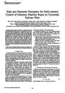
where z(k ) denotes measurement vector. w(k) is the system noise and assumed to be a zero-mean white Gaussian noise which is independent of x(k ) , with covariance Q and the measurement noise v(k) is a zero-mean white Gaussian noise that is independent of x(k ) and w(k), with covariance V. The system model is shown is Figure 1. Now that the complete system model (the augmented model), an extended Kalman fitler can be applied. w
U d (k )
Bd (
xˆ ( k +1) )
z
Ad (
−1
xˆ ( k )
)
z
−1
d
(
)
3. F (k ) = ∂f (⋅) ∂x a ( k )
d
(
)
d
xa ( k )
4. M ( k + 1) = F ( k ) P ( k )F ( k )T + G ( k )QG ( k )T
(
Zk
H
Prediction process: 1. The determination of the xˆ (0), ˆ (0), P (0) initial values 2. x (k + 1) = A ˆ (k ) xˆ (k ) + B ˆ (k ) u (k )
Correction process: 5. K (k + 1) = M(k + 1)HT HM(k + 1)HT + R
v
G (k )
The principle of the filtering algorithm is as follows. At time stage k, the predictions of the augmented state vector (the state vector and the parameter vector) are calculated from the input ud(k) and the estimation of the augmented state vector xa (k) assuming that there is no noise. The covariance matrix of the prediction error M(k+1), that of the estimation error P(k+1) and Kalman gain matrix K(k+1) are updated. At time stage k+1, the estimation of the augmented state vecor are obtained by revising the predictions by the difference between the measurements of the stator currents and the predictions via the Kalman gain matrix, which is determined so that the covariance matrix of the estimation error is the smallest value. The filtering process is summarized as follows
ˆ (k )
−1
6.
P ( k + 1) = ( − K ( k + 1) H ) M ( k + 1)
7.
xˆ ( k + 1) = x ( k + 1) + L( k + 1) ( Z( k + 1) − Hy ( k + 1) )
8.
ˆ ( k + 1) = ˆ ( k ) + N ( k + 1) ( Z ( k + 1) − Hy ( k + 1) )
9. where x(k ) xˆ(k ) ˆ (k )
Fig. 1. Discrete state model of the induction motor
)
Go to 2.
:prediction of the state vector : estimation of the state vector
: estimation of the Parameter state vector M(k + 1) : Covariance matrix of the prediction error
V. EXTENDED KALMAN F LTER In the induction motor model which is given by (21) and (22), it is possible to use the EKF to estimate the augmented state vector x a (k ) . The algorithm is implemented by using a
P ( k + 1) : Covariance matrix of the estimation error T : Kalman gain matrix K ( k + 1) = LT ( k + 1) NT ( k + 1)
perturbation technique to linearise the non-linear model around the most recent estimate [10]. The linearization process requires that partial derivative or Jacobean matrice be obtained for the non-linear functions in the model. In the augenment motor model given by (17) the state equations are non-linear, and therefore Jacobean matrice is required as defined below
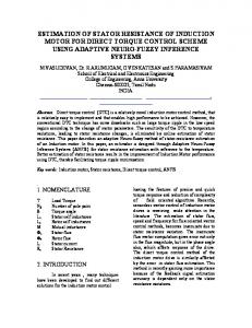
I : Unit matrix. The structure of the Kalman filter is given in Fig 2. ˆ(k ) x A d ( ˆ ( k )) Ud ( k )
F(t ) =
∂f (⋅) ∂xa xˆ a (t )
z −1
B d ( ˆ ( k ))
Z( k + 1 )
x(k +1)
xˆ ( k + 1)
L(k + 1) K (k + 1)
N(k + 1)
=
A d ( ˆ (k ) ) 04 x4
∂ A d ( ˆ ( k ) ) xˆ (dk ) + B d ( ˆ ( k ) )u d ( k ) ∂θ I4x4
(
)
ˆ ( k + 1)
(23) ˆ (k )
z −1 H
Figure 2. The structure of the filtering algorithm
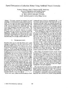
VI. ESTIMATION RESULTS The block diagram of the experimental setup and the proposed estimation is given in Figure 3. As shown in the figure, the proposed algorithm uses the experimental measurements of the supply voltage, the stator currents and rotor angular speed. The induction motor used in the experimental setup has the properties given in Appendix. Supply voltages having waveforms of sinusoidal and sixsteps were seperately implemented on this motor under 1 Nm load ; and the stator current and rotor angular speed measurements corresponding to these voltage supplies were sampled online with 5Khz sampling frequency. The state and parameter estimation process was implemented using EKF algorithm.
( a)
(b)
(c) ˆids( k ) ˆiqs ( k ) ϕˆ dr ( k ) ϕˆ qr ( k )
ˆ( k )
Figure 3. The block diagram of the experimental setup and proposed estimation algorithm.
For the implementation of EKF, the process and measurement noises are assumed to be white and normally distributed with their covariance matrices given by Q= 0.005 0
0
, V= 0 . 05
0.005
0
0 0 . 05
(d)
The initial estimated value of the state vectors was set randomly. For the initial value of covariance matrix of the estimation error P(0) =
I4 x 4 0
0 I4 x 4
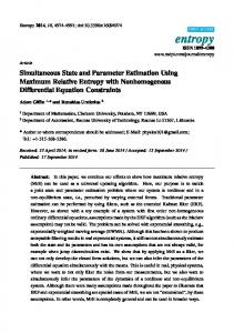
was used and was taken as = 104. The desired estimation was obtained for the higher values of . The estimation results for direct and six-step fed are shown in Fig.4 and Fig.5, respectively. Figures show that the proposed EKF based estimation algorithm is cabaple the states and parameters of the induction motor.
(e) Figure 4. Results of estimation for sinusoidal supply from implementation. (a) Rotor angular speed measurement curve. (c) The results for estimation error of iqs (b) The results for rotor flux in q axes. (c) The results for rotor flux in d axes. (e) The results for parameter estimation in pu.
VII. CONCLUSION
(a)
We have proposed a EKF based state and parameter estimator for a squirrel-cage induction motor. The performance of the proposed algorithm is compared with actual results for sinusoidal and six-steps waveforms fed. The comparison of the simulation and implementation results show that the proposed algorithm yields accurate estimated values of the rotor flux components and motor parameters. In this study, sinusoidal and six-steps waveforms was used for proposed algorithm. PWM waveform should be tested to confirm the applicability of the EKF. APPEND X TABLE I. INDUCTION MOTOR DATA 380 V, 3.4 A, 1.5 Kw, 3000 Rpm, 50Hz, star
(b)
Ls[H]
Lr[H]
M[H] Rs[
0,335
0,335
0,320
]
Rr[ ]
5
3,073
J[Js2]
p
0.03640
2
REFERENCES [1] B.K. Bose, Modern Power Electronics ad AC Drives, Prentice-Hall, USA, 2002. [2] G. C. Verghese, S.R. Sanders, “Observer for Flux Estimation in Induction Machines”, IEEE Trans. On Industrial Elect., Vol.35, No. 1, February 1988. [3] T. Matsuo and T.A. Lipo, “ A Rotor Parameter Identification Scheme for (c)
Vector-Controlled Induction Motor Drives”, IEEE Trans. on Ind. Appl., Vol. A 21, No. 4, pp. 624-612, May-June, 1985. [4] H. A. Toliyat, E. Levi, M. Raina, “A rewiev of RFO Induction Motor Parameter Estimation Techniques”, IEEE Trans. On Energy Conversion, Vol. 18, No.2, June 2003. [5] V.Vasic, S. N. Vukosavic, “A stator resistance estimation scheme for speed sersorless rotor flux oriented induction motor drives”, IEEE Trans. On Energy Conversion,Vol 18, No.4, December 2003. [6] B. Karanayil, M. F. Rahman and C. Grantham, “Online Stator and Rotor
(d)
Resistance Estimation Scheme Using Artifical Neural Networks for Vector Controlled Speed Sensorless Induction Motor Drive”, IEEE Trans. On Industrial Elect., Vol.54, No. 1, February 2007. [7] L. Salvatore, S. Stasi, L T., “A new EKF-Based Algorithm for Flux Estimation in Induction Machines”, IEEE Trans. On Ind. Electr., Vol.40, No.5, pp. 496-504, 1993. [8] La Cava M., C. Picard, F. Ranieri " Application of he Extended Kalman Filter to Parameter and State Estimation of Induction Motors “, Int. Journal of Modelling and Simulaton, Vol.9, No.3, pp. 85-89, 1989.
(e) Figure 5. Results of estimation for six-steps supply from implementation. (a) Rotor angular speed measurement curve. (b) The results for estimation error of iqs (c) The results for rotor flux in q axes. (d) The results for rotor flux in d axes. (e) The results for parameter estimation in pu.
[9] Gene H. Hostetter, Digital Control System Design , Oxford University Press, USA 1987. [10] A. H. Jazwinski, Stochastic Processes and FilteringTheory, Academic Press, London, 1970.