Parametric Design and Multi-objective Optimization of SWATH C. Papandreou 1) , A. Papanikolaou 2) 1) National Technical University of Athens, School of Naval Architecture and Marine Engineering, Athens, Greece,
[email protected] 2) National Technical University of Athens, School of Naval Architecture and Marine Engineering, Ship Design Laboratory, Athens, Greece, http://www.naval.ntua.gr/sdl,
[email protected]
Abstract The present paper deals with the development of a parametric design software tool for the fast and robust optimization of SWATH (Small Waterplane Area Twin Hull) type ships and twin hull ships in general. The prototype SWATH used for validating the results of the developed software is the well known NTUA-SDL ferry design Aegean Queen. The core of the present paper refers to the development of the parametric hull modeling that enables the automated hull form optimization of the wetted body. Considering that the design concerns a passenger ship that needs to adapt to different seasonal demands, the optimization was carried out with regards to two (2) different operational speeds. The first one assumes a high sailing speed for summer operation, while the second one is a relatively low speed for serving at a non-commercial period (winter season). The conducted study demonstrated that the resulting innovative SWATH design has very competitive characteristics regarding powering demand and fuel efficiency, while it disposes the inherent best seakeeping properties especially for operation in short seas, like in the Aegean archipelagos.
The reasoning for choosing SWATH as a subject of study in this research is deriving from the anticipated hydrodynamic/ operational advantages of the SWATH compared to a conventional monohull, while taking into account that the whole concept is applied to a fast passenger ship design, namely:
SWATH main disadvantages against monohull are:
Keywords SWATH; Parametric design; Multi-Objective Optimization; Hydrodynamic design
Introduction
The objectives of the presented research project, which was conducted in the frame of the diploma thesis of the first author at NTUA, are listed in the following:
Development of a rapid marine transit system for service in the Aegean Sea. Development of a parametric design procedure system for Small Waterplane Area Twin Hull (SWATH) ships. Development of a methodology for fast and robust SWATH ship optimization. Validation of the resistance and powering results (predictions and tests) on the basis of comparable data of the NTUA-SDL design Aegean Queen [1], [2].
Superior sea-keeping behavior. Extremely good maneuvering. Adequate stability in all conditions. Less required horsepower, especially in high speed regions and real sea conditions. Reduced journey time. Low noise level and vibrations. Comfort due to the large deck space including superior seaworthiness. Shorter embarkation/ disembarkation time. Attractiveness for passengers.
Larger frictional resistance of the ship, because of the increased wetted surface of the twin hull, which is important for the resistance at low speeds only. The sensitivity to changes of draft and trim for change of loading, due to the small waterplane area. The necessity to consider fitting stabilizing fins to reduce pitching and avoid likely vertical plane instability ("neck diving"). Higher construction cost. New technology vessel; appreciable risk for investors.
In view of the above pros and cons, SWATH ships are nowadays covering only a distinct niche in the market of merchant and naval ships, namely where a demand for appreciable speed is associated with good seakeeping capability. Thus, they are commonly employed as small passenger ships and ferries, small pleasure crafts and cruise vessels, pilot boats, offshore
support vessels, research and ocean surveillance vessels, offshore patrol vessels and naval corvettes etc.
Strut The second part is the strut. It is supporting the deck on the gondola. Struts must be hydrodynamically optimized so that the wave resistance is the least possible. Again, the following assumptions should be considered: Struts lie in vertical planes; the single strut per hull concept is employed. Strut profiles parabolic nose, parallel midbody and parabolic tail. Their lengths can be varied but in a standard rate of gondolas lengths.
Box The third main part of the SWATH is the box. It forms the deck of the vessel, where the cars are loaded and on which ship's superstructure is erected. Since the box does not contribute to the hydrodynamic resistance of the ship it was not studied herein thoroughly; therefore it was not optimized but designed only for presentation purposes.
Development of the parametric design model The design of a SWATH vessel, as of any ship, is governed by the economical and technical requirements of the ship owner, physical restrictions, regulations about functionality and safety, as well as on the new technological evolutions. The engineer must cope with all the above and conclude on a design solution that is optimized with respect to economy and a productive exploitation of the initial investment. The consideration of all the above is more difficult when the vessel is of a relatively new type and its basic elements need to be determined by first principles approach, even more because of the lack of data from sister/similar ships. The design procedure, however, is following to a great extent the well-known design spiral [3]. For the development of the parametric model, Friendship Framework software system [4] seems a suitable software platform to work with. The adopted procedure is described in the following. At first, a conventional parametric model for the SWATH hull form was created within the GUI interface of Friendship Framework. This was composed of three parts.
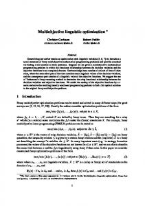
At the abovementioned parametric model another important parameter was added in order to enable the local form optimization; namely, a parameter expressing the displacement distribution. It was created using the feature programming embedded in the Friendship Framework. As a result, the midbody is not parallel (of constant cross section) any more, but it is determined by a guidance curve that can be modified for the controlled alteration of the displacement distribution. The two figures below depict how this particular parameter can alter the model.
Fig. 1: Swath components
Gondola The first part was the "gondola". We call gondola the lower hull of the ship that holds most of the displacement and it is fully submerged under the free surface of the sea. It is assumed that the gondola hull has a standard form with the following characteristics: Lower hulls are of circular cross section. Lower hulls consist of ellipsoidal nose, parallel midbody and parabolic tail with variable length. Lower hull axes are horizontal, parallel and symmetric to the centerplane.
Fig. 2: Displacement distribution parameter variance
Also, it should be stressed that the radius of the gondola Rad is not an independent parameter, but results from the requirement that a hull form of constant displacement of 1,000 tonnes is generated, to enable a direct comparison with the Aegean Queen concept. For reasons of comparability, also ship's draft was kept constant and at a maximum of 5m. However, during the operation of the vessel, displacement is anticipated to change. Thus, extreme cases of 10% variation of the
initial displacement were considered and the draft was varying between min. 4m and max. 5m. The following table and sketch define the design parameters of the generated SWATH model. Table 1 : SWATH Hull Form Design Parameters
Parameters Length of gondola (Lgon) Lgn Lgt Radmid Latsep Bstrut Lstr_n Lstr_t
Explanation Lower Hull Length Lower Hull Nose Length Lower Hull Tail Length Displacement Distribution Parameter Half Distance Between Lower Hulls Strut Beam Strut Nose Length Strut Tail Length
The developed optimization procedure is as follows:
Initiation of the design "engine" being responsible to attribute values to the parameters (depending on the type of the design engine).
Friendship Framework assigns the parametric model with the design engine initial values.
Transfer of the geometry of the model in a certain format recognizable by the Michlet[5] code to calculate ship's resistance for two speeds.
Fig. 3 : Form design parameters definition
Optimization Model/Procedure The present “optimization modeling system” consists of several subsystems suitable to approach the design of a novel SWATH in a holistic way. The target of this approach is to create a fully parametric model able to vary the size of the ship in a wide range of dimensions and form parameters (exploration of design space) and to provide valuable information regarding numerous features and properties of the subject ship. Following this design exploration, a multi-stage optimization process takes place based on the resulting most promising design variants. In this simulation driven design the designer is able to handle simultaneously as many objectives as necessary. Obviously this is not a trivial task, therefore a number of assumptions have to be made and the design problem has to be viewed by specific perspectives, in order to define the boundaries and the targets of the investigation. The main idea is to set up a flexible parametric model that is able to predict automatically and accurately a large number of the SWATH properties regarding geometry, resistance and capacity. Therefore a number of specialized tools has been developed and integrated in the software system, while the automated character of the procedure increases drastically the efficiency of the optimization.
The results are exported to an output file.
The exported results are stored by the Friendship Framework at the design engine computation file along with the corresponding parameters.
Design engine alters the parameters and the whole process is being repeated until the population of resulting designs is satisfactory and results have The optimization process includes two stages as converged . outlined below: The optimization process includes two stages as outlined below:
Automated and systematic exploration of the multidimensional design space with analysis sequences for more than 500 designs in the frame of a so-called Design of Experiments (DOE) procedure by use of a SOBOL algorithm. Automated deterministic detailed optimization of the best selected variants from DOE, with multi-objective genetic algorithms, utilizing many form parameters and design objectives.
For the multi-objective optimization, the Nondominated Sorting Algorithm II (NSGAII [6]) is utilized. The main advantages of this algorithm are that Pareto-based ranking schemes are applied and “trapping” between local maxima (or minima) is avoided. Exactly the same task was repeated with a Multi-objective Simulated Annealing algorithm (MOSA) for validating the results.
Constraints and Optimization Objectives The introduced constraints for controlling the feasible designs were the following:
Displacement should be marginally equal to 1,000 tonnes. Area of waterplane (Awl) should not be less than a limit of about 120 m2 in order to avoid significant changes to draft. For practical reasons (fitting of machinery outfitting) Bstr should not be less than 1.6 m. Draft less or marginally equal to 5m. Lstr_n,Lstr_t : should be given as ratio of Lgn, Lgt (no more than 30-60 %, depending on radius) for practical reasons (to have an uniform onset flow to the propeller, etc.)
The holistic design approach is implemented to this design problem with the following objectives that reflect clearly the scope of this project:
Minimization of the total resistance (Rt) at V=15.5Kn Minimization of the total resistance (Rt) at V=31Kn
Calculation of Resistance The total resistance of the SWATH ship is calculated as the sum of viscous and wave resistance Rt = Rw + Rv
(1)
We apply herein Michell’s thin ship theory to the evaluation of the wave resistance, because of its simplicity and impressive computational efficiency. Alternatively, the 2nd author of this paper has used in the past also other methods, as shown in Ref. [7]. Recalling Michell's thin-ship theory, the wave resistance of a single hull, mathematically described by the equation y = ±Y(x, z), is obtained by the sum of three integrals, which are evaluated as follows acc. to E. O. Tuck [8]. 1. First, we evaluate for all stations x, and all values between 0 and π/2 of a wave propagation angle θ, the integral
(2) where κ = g/U2 is the wave number, and the integral is taken in the z direction over ship's draft. The offsets Y(x, z), namely halfwidths at station x and waterline z, are given with the hull form offset data. 2. Next, we evaluate simultaneously a pair of integrals along ship's length, namely (3)
3.
and a similar integral for Q(θ) having sin ( ) instead of cos ( ) in the integrand. The integrand of this integral is complemented by the quantity F, evaluated above (Eq. 2). Finally, we integrate the contributions to the total wave resistance Rw of waves for all directions θ, namely
(4) where c = 4ρg4/(πU6) is a constant depending only on the speed U and g = gravity, ρ = water density. The above is only a slight variation from standard versions of the original Michell integral, namely an integration by parts has been used to express the integral in terms of the actual offsets Y (x, z), rather than its longitudinal derivative Yx. The above is modified for a twin-hull vessel, with its demihull-centerplanes being separated by w (=2x Latsep), namely we need to correct P and Q by multiplying them with the factor (5) The wave resistance Rw of the twin hull vessel is now given by:
(6) Proceeding to the viscous resistance Rv [9], it can be commonly written as : Fig. 5: Rt (at 31Kn) - Radmid
Cv ρ S U2,
(7)
where, ρ is the water density and S the wetted surface area of the hull and the viscous resistance coefficient is calculated by Cv = (l+k) Cf
(8)
From Figs 4 and 5, it shows that the Radmid parameter has a reverse effect on Rt for the two (2) speeds. In view of this, the displacement tends to concentrate at the center for the low speed, whilst for the high speed the displacement concentrates at the edges for least resistance (this was also confirmed earlier by [1],[2]).
where the frictional resistance Cf is estimated using the ITTC 1957 ship correlation line Cf = 0.075/(log10Rn-2)2
(9)
where Rn= UL/ν is the Reynolds number; ν is the water kinematic viscosity. The full length of the waterline is used for L in the definition of the Reynolds number.
Fig. 6: Rt (at 15.5Kn) - Bstr
The form factor k in equ. (8) is herein estimated by an empirical formula [10], namely k = 0.0097(thetaentry + thetaexit)
(10)
Here, thetaentry and thetaexit are the entry respectively exit half-angles (in degrees) of the bow and stern section of the waterplane. Care must be taken in applying this form factor, as it only applies to slender canoe type bodies. In an optimization problem, where the shape is not constrained, there could be inaccuracies with undesirable side-effects.
Design of Experiment (DOE)
Fig. 7: Rt (at 31Kn) - Bstr
The dependence of Rt on the Bstr parameter is logical and conceivable for both speeds and -as it appears in the above figures- the greater the value the more intense the created waves resulting into higher resulting wave resistance, and hence total resistance.
The results of the design of experiment are summarized and explained at the following figures:
Fig. 8: Rt (at 15.5Kn) - Latsep
Fig. 4: Rt (at 15.5Kn) – Radmid
Fig. 9: Rt (at 31Kn) - Latsep
The dependence of Rt on the “Latsep” parameter appears more complicated. It presents a local minimum for the speed of 15.5kn, but nothing similar shows for the speed of 31kn, where the maximum separation corresponds to the optimum. This is not surprising and reflects the interaction of the wave systems generated by the two demihulls: at lower speeds and smaller lengths of the generated waves, the two demihulls generate wave systems meeting between the two hulls, thus a cancellation effect can be triggered for specific demihull separation distance (and even a negative 'interaction' resistance, see Papanikolaou et al, ONR 1996[7]); whereas, at higher speeds and wave lengths, the interaction effects continuously decrease for larger separation distances until they entirely disappear.
Fig. 13: Rt (at 31Kn) - Lgn
The Lgn parameter is also contradictory for the two (2) speeds as illustrated in the above figures (Fig. 12, Fig. 13). Specifically, with respect to the low speed a larger Lgn value is better, whereas for the high speed the least appears the best, even though the effect is not that strong. This effect is related to the modeling of the viscous-form parameter (see, equ. 10).
Fig. 10: Rt (at 15.5Kn) - Lgon
Fig. 14: Rt (at 15.5Kn) - Lgt
Fig. 11: Rt (at 31Kn) - Lgon
Fig. 15: Rt (at 31Kn) - Lgt
The effect of the Lgon parameter reflects again an interesting physical phenomenon. The data obtained for 15.5kn show a continuous increase of the total resistance with Lgon, whereas or 31kn the opposite is happening. This is not surprising, because with the increase of Lgon the wetted surface steadily increases and this causes an increase of the frictional resistance, which is dominating at low speed (low Froude number); at higher speeds, wave resistance is dominating and this calls for more elongated, slender hulls.
The same applies to the effect of the Lgt parameter.
Fig. 16: Rt (at 15.5Kn) - Lstr_n
Fig. 12: Rt (at 15.5Kn) - Lgn
Fig. 17: Rt (at 31Kn) - Lstr_n
Likewise the effect of the Lstr_n and Lstr_t parameters on Rt (Figs. 16, 17, 18, 19) could be explained, even though these effects are herein less significant in terms of observed absolute values. It should be noted, however, that presently applied hydrodynamic models are not sensitive enough to capture these effects.
Table 2: Parameter boundaries for optimization
Fig. 18: Rt (at 15.5Kn) - Lstr_t
Fig. 19: Rt (at 31Kn) - Lstr_t
The results of the DOE showed the basic trends of each parameter, the optimal values and their impact on the total resistance. It should be pointed out that during the SOBOL or Exhaustive Search algorithm, all other parameters, except for the one investigated, were kept fixed.
Fig. 20: NSGA II –Results Table 3: NSGA II - Boundaries
Genetic algorithm optimization Following the design of experiment procedure DOE, which enabled the exploration of the design space, a systematic formal multi-objective optimization is conducted. The range for the parameters has been greatly reduced after the thorough DOE. As a result, the region of promising variants within the space of feasible designs has been identified. In this region, an optimization will be now conducted in order to find the best designs and the Pareto-Frontier. The NSGA-II [6] genetic algorithm was utilized to perform the multicriteria optimization. This genetic algorithm enabled to further reduce the space of optimal designs and also ensured that the algorithm was not trapped to local optima (often due to the elitism). The same procedure was finally repeated with the MOSA algorithm to be absolutely confident about the results.
It should be mentioned that the non-feasible designs were excluded from the above Fig. 20 diagram. In every diagram, the reference design is not close to the ParetoFrontier in terms of the objectives. That proves the fact that there was a merit, and that the genetic algorithm has completed its task successfully. Therefore it can be assumed that the NSGA II [6] concluded to the best compromises for the two objectives.
Table 6: Best Designs (Evaluations)
The best designs illustrated above were created by an objective function with respect to the total resistance, as following: Fig. 21: MOSA –Results
Table 4: MOSA – Boundaries
For the same reasoning, it can be assumed that the MOSA algorithm also found the best compromises for the two objectives.
Best Designs The multi-objective optimization generated a wide variety of feasible designs. It also identified designs of best compromise, while keeping the constraints into an acceptable range. The identified Pareto frontiers in the above diagrams illustrate this fact. In order to choose the best designs, a new objective function must be introduced to express specific needs of the decision maker. There are formal procedures for this task like the Multiple Attribute Decision Making (MADM) presented by Sen and Yang [11]. In the present case, a manual exploration of the Pareto frontier with the objective function is conducted.
R155 is the best design for the low speed. It is assumed that the corresponding vessel is designed not to run at the high speed, so the high speed total resistance is not taken into consideration. R155_mostly is the best design alternative mostly for the low speed. It is assumed that the SWATH may run the high speed a few times during its lifetime. Best_equal is the optimal design assuming that half of the time the ship will run at the low speed and the other half at the high one. Thus, both low and high speed total resistances were equally taken into account. R31_mostly is the optimal design mostly for the high speed and obviously it is considered that it will run this speed at most of its journeys. R31 finally is the best model for the high speed and hence the total resistance for the low speed is not considered.
SHIPFLOW® Validation Taking into account that the employed MICHLET® code is based on a simplified approach to the wave resistance estimation, while it is a very fast code, a validation of the obtained results was necessary. For this, the well known code SHIPFLOW® of FLOWTECH was used [12]. The validation was conducted for few selected designs.
Table 5: Best Designs (Parameters)
Here we present the results of SHIPFLOW® for the five (5) best designs:
R155
R31
Fig. 26: Rt –V (Shipflow for R31) Fig. 22: Rt –V (Shipflow for R155)
R155_mostly
Generally, the above figures showed that the values of total resistance estimated by SHIPFLOW® are lower than that of MICHLET®, especially at higher speeds.
Comparison of AQ3 with AQ Since the initial dimension setting of the studied SWATH ship (AQ3) was based on the respective data of the Passenger Ferry Aegean Queen (AQ), a comparison of the herein obtained resistance results should be made with those of AQ. Corresponding results are compared at the following table:
Fig. 23: Rt –V (Shipflow for R155_mostly)
Table 7 Compared results of AQ & AQ3
Best_equal
Fig. 24: Rt –V (Shipflow for Best_equal)
R31_mostly
Overall, the AQ3 resistance results of all variants are better than those of AQ, especially at lower speeds. In this comparison, however, some important factors should be mentioned: The predicted values of AQ at the high speed proved smaller compared to the experimental values, whereas the comparison at low speed is much better. This is possibly attributed to various non-potential flow phenomena, like flow separation, that were not properly considered in the used resistance estimation methods; also, the variation of the mean draft and trim of the vessel was not taken into account in the theoretical predictions.
Fig. 25: Rt –V (Shipflow for R31_mostly)
AQ had a constraint lower hull (gondola) and strut to fit the engines. This increased the total resistance of AQ compared to an unconstrained optimized design. AQ3, however, did not require this adjustment due to the technological improvements of diesel engines of same power, which now fit in much lesser space.
Conclusions
The work presented herein, demonstrated the applicability of an advanced technology ship design approach using parametric design tools for optimization at the conceptual design phase. The core of this method is found in the fully parametric model, which is applicable to a wide range of global dimensions and local characteristics of a SWATH like hull form, retaining its fairness of shape and feasibility of its properties. It is based on the coupling of the computer aided engineering tool FriendshipFramework, and the computer workbench MICHLET, (or the flow solver SHIPFLOW). Regarding the investigated design concept, it was shown, that a special type of ship, like a SWATH, that is unconventional and without a parallel midbody, has advantageous characteristics regarding powering demands from all aspects as shown above (next to its superior seakeeping, not shown herein). The great advantage of the developed CAD procedure is its high processing speed. One of the most laborious parts of the optimization problem is to explore the design space and find the optimal parameter values. This requires a huge time and computer powering. The CAD system presented herein is able to achieve this target fast enough in order to obtain an early assessment for the best designs. After that part, the validation of the results can be achieved using more high fidelity software tools. Thus concluding, it is not only the significant processing time gained in the optimization process, but also the exploration of the huge design space within processing time. Finally, the created tool can also be utilized in manifold optimization concepts deviating from the SWATH design. Many other twin or multihull hull forms can be readily investigated by the same CAD procedure. Two additional case studies were carried out (trimaran, tetramaran) in the diploma thesis of the first author [13] and promising results were obtained.
Acknowledgments The first author likes to express his gratitude to the staff of NTUA-SDL and of Friendship Systems for supporting him in his thesis. He thanks also Dr. Leo Lazauskas for disposing him the code MICHLET free of charge for the conduct of this study.
References 1. Papanikolaou,
2.
3.
4.
5. 6.
7.
8.
9.
10.
Α., Zaraphonitis, G., Androulakakis, Μ., "Hydrodynamic Aspects and Conceptual Design of SWATH vessels", Final Report to the Greek Secr. General for Res. and Tech., ΠΡΟΠΕ 86Γ924, NTUA, March 1990. Papanikolaou, Α., Zaraphonitis, G., Androulakakis, Μ., "Preliminary Design of a High-Speed SWATH Passenger Car/ Ferry", Journal Marine Technology, SNAME, Vol. 28, Νο. 3, ρρ.129-141, May 1991. Papanikolaou A., “Ship Design-Methodologies of Preliminary Ship Design (in Greek)”, Vol. 1, SYMEON Publisher, 2009 FRIENDSHIP-SYSTEMS, Potsdam. FRIENDSHIP-FRAMEWORK User Guide, Nov. 2009, http://www.friendshipsystems.com/forum/ Lazauskas L., MICHLET® user manual, 2010 Open Source Engineering: Multiobjective Optimisation and Genetic Algorithms, http://www.openeering.com/sites/default/files/ Multiobjective_Optimization_NSGAII_0.pdf. Papanikolaou Α., Kaklis Ρ., Koskinas C., Spanos D., "Hydrodynamic Optimization of Fast Displacement Catamarans", Proc. 2lst Int. Symposium on Naval Hydrodynamics, ONR' 96, Trondheim, June 1996. E.O. Tuck , “Wave resistance of thin ships and catamarans” Dept. Applied Mathematics, Reprint of Internal Report T8701 , University of Adelaide 1997. E.O. Tuck & L. Lazauskas “Unconstrained ships with minimum total drag”, Dept. Applied Mathematics Technical Report , University of Adelaide, Dec. 1996. Scragg, Carl A. and Nelson, Bruce D., “The design of an eight-oared rowing shell”, Marine Tech., Vol. 30, No. 2, Apr. 1993, pp.\ 84--99.
11. Sen P., Yang, JB, Multiple Criteria Decision Support in Engineering Design, SPRINGER Publ., 1998 12. SHIPFLOW®, FLOWTECH International AB, www.flowtech.se. 13. Papandreou, C., “Parametric Design and Multiobjective Optimization of Swath”, Diploma Thesis, NTUA-SDL, June 2013