[8] Kourosh Gharachorloo, Madhu Sharma, Simon Steely, and Stephen Van Doren. ... [18] Dan Teodosiu, Joel Baxter, Kinshuk Govil, John Chapin, Mendel ...
Part II: A Methodology for Developing Deadlock-Free Dynamic Network Reconfiguration Processes Olav Lysne, Timothy Mark Pinkston and Jos´e Duato Abstract Dynamic network reconfiguration is defined as the process of changing from one routing function to another while the network remains up and running. The main challenge is in avoiding deadlock anomalies while keeping restrictions on packet injection and forwarding minimal. Current approaches either require virtual channels in the network or they work only for a limited set of routing algorithms and/or fault patterns. In this paper, we present a methodology for devising deadlock free and dynamic transitions between old and new routing functions that is consistent with newly proposed theory [1]. The methodology is independent of topology, can be applied to any deadlock-free routing function, and puts no restrictions on the routing function changes that can be supported. Furthermore, it does not require any virtual channels to guarantee deadlock freedom. This research is motivated by current trends toward using increasingly larger Internet and transaction processing servers based on clusters of PCs that have very high availability and dependability requirements, as well as other local, system, and storage area network-based computing systems. Keywords: Interconnection network, dynamic reconfiguration, deadlock-freedom, methodology.
1 Introduction System availability, reliability, and predictability are becoming increasingly important as system size and demand increase. This is especially true for high-end servers (web, database, videoon-demand servers, data centers, etc.), which are currently based on clusters of PCs and/or highly parallel computers. In these systems, the network interconnecting the processing nodes among them and to I/O devices plays a very important role towards achieving high system availability. Many techniques—including link-level flow control [2, 3, 4] and deadlock-free routing [5, 6, 7]— have been developed over recent years that enable increased network dependability. These techniques are in common use today in interprocessor communication networks (e.g., multiprocessors/multicomputers [8, 9, 10]), system area networks (e.g., I/O and storage networks like Servernet [11] and InfiniBand [12]), and local area networks (e.g., cluster networks such as Autonet [13], Myrinet [14, 15], and even in recent Ethernet specifications [16]). Flow control implemented at the link level requires that the receiving side of a link has enough free buffer space to receive the amount of data being pipelined through the link by the sending side. This guarantees that no packets will be dropped on account of buffer overflow. When a deadlock-free1 routing algorithm 1
A set of packets is said to be deadlocked if all packets in the set must wait for another packet in the set to proceed before progress can be made. Conversely, deadlock freedom abounds if no such set of packets can exist in the network.
1
is defined along with link-level flow control and error correction, all packets sent by a fault-free network eventually arrive at their destinations, ensuring a certain amount of dependability. In some situations, however, the premises on which the routing algorithm and/or network topology are defined may break, which affects the network’s dependability. This can happen, for example, when the topology of the network changes, either involuntarily due to failing/faulty components or voluntarily due to hot removal or addition of components. This normally requires the network routing algorithm (a.k.a., routing function) to be reconfigured in order to (re)establish full network connectivity among the attached nodes. In transitioning between the old and new routing functions during network reconfiguration, additional dependencies among network resources may be introduced, causing what is referred to as reconfiguration-induced deadlock. Current techniques typically handle this situation through static reconfiguration—meaning that application traffic is stopped and, usually, dropped from the network during the reconfiguration process (see, for example, [17, 18]). While this approach guarantees the prevention of reconfiguration-induced deadlock, it can lead to unacceptable packet latencies and dropping frequencies for many applications like compute data-centers, high availability web-servers, video-servers and process control servers. 2 With dynamic reconfiguration, the idea is to allow user traffic to continue uninterruptedly during the time that the network is reconfigured, thus reducing the number of packets that miss their real-time/QoS deadline. Recently, some key efforts have been put toward addressing the issue of deadlock-free dynamic reconfiguration within the context of link-level flow controlled interconnection networks. In [20], a Partial Progressive Reconfiguration (PPR) technique is proposed that allows arbitrary networks to migrate between two instantiations of up*/down* routing. The effect of load and network size on PPR performance is evaluated in [21]. Another approach is the NetRec scheme [22] which requires every switch to maintain information about switches some number of hops away. Yet another approach is the Double Scheme [23], where the idea is to use two required sets of virtual channels in the network which act as two disjoint virtual network layers during reconfiguration. The basic idea is first to drain one virtual network layer and reconfigure it while the other is fully up and running, then to drain and reconfigure the other virtual network layer while 2
In [19] it is reported that in a small simulated Infiniband-system with 8 switches, the network downtime due to static reconfiguration can be as high as 5 milliseconds, leading to a packet loss of as many as 70000 packets.
2
the first is up and running, thus allowing “always on” packet delivery during reconfiguration. An orthogonal approach which may be applicable on top of all of the above techniques is described in [24], where for up*/down* routing, only parts of the network (i.e., the “skyline”) need to be reconfigured on a network change. Solid theoretical support on which dynamic reconfiguration design methodologies and techniques can be proven deadlock-free can be found in [1]. This paper applies the newly proposed theory put forth in [1] by presenting a simple and straightforward—yet powerful—methodology for developing deadlock-free dynamic reconfiguration processes. Given as a starting point is known information about the old and new routing functions (i.e., through some topology discovery process [19]) which, themselves, must be deadlockfree. That is, given that the new topology is discovered and a new deadlock-free routing function for that topology can be computed, our methodology can be used to prescribe a deadlock-free process for deploying it throughout the network—possibly through a sequence of steps consisting of updates using some intermediate routing functions derivable from the methodology. In contrast to previous approaches mentioned above, the proposed methodology puts no restrictions on the types of routing functions, switching techniques, network topologies, nor virtual network layering capability it supports. It is capable of generating new and previously unknown reconfiguration processes as well as straightforwardly reproducing previously proposed processes such as those mentioned above—which verifies its validity. The main contribution of this paper is in developing a simple and straightforward methodology useful for deriving a wide variety of dynamic reconfiguration processes that have the properties of keeping packet loss and halting of packet injection low while, at the same time, are free from reconfiguration-induced deadlock. No performance evaluation or simulation results are presented here as such analysis is beyond the scope of this work. Such analysis for techniques derivable from this methodology can be found in [21, 23]. The rest of the paper is organized as follows. In Section 2, we present the basic assumptions and observations on which the methodology is based. We also present notation and formalism that is consistent with the theory presented in [1]. This is used to prove deadlock-free properties of the reconfiguration processes derivable from this work. The proposed methodology is presented in Section 3, and examples of its use are described in Sections 4, 5, and 6. In Section 7, we consider the possibilities for automating the methodology before we conclusions in Section 8. 3
2 Basic Assumptions, Observations, Notation, Definitions and Lemma The proposed methodology for developing reconfiguration processes aims at minimizing restrictions on packet delivery and injection of packets throughout the reconfiguration process. It does so while guaranteeing freedom from reconfiguration-induced deadlock. To better understand the methodology, the reader should be familiar with interconnection network basics, including the notions of packets, links, channels, switches, link-level flow control, routing functions, channel dependency graphs and escape paths [7]. Formal treatment of these concepts as they relate to deadlock-free network reconfiguration can also be found in a related theory paper [1]. The methodology assumes that both the old and the new routing functions are known a priori through some network discovery preprocessing step [19]. This information is viewed as input to the methodology. In the case of reconfiguration due to a fault, all packets routed to or through a fault-effected link or switch are considered corrupted and, thus, are discarded until a new routing choice is provided. No packets are discarded, however, as a means of dealing with reconfigurationinduced deadlock. Such deadlocks could arise from packets being routed under the influence of different routing functions that may be partially active in the network at the same time (i.e., old and new ones). Note that reconfiguration processes asynchronously update the routing function at different switches in the network. Such partially-active, independently-defined routing functions constitute the prevailing routing function [1] seen by packets in the network. Residual dependencies on channels of older routing functions maintained by packets as they route through a dynamically reconfigured network are referred to as ghost dependencies [1, 23]. These dependencies are produced by routing choices that have been removed but whose effects are still noticeable through packets that were routed using those routing options and are still in the network. The proposed methodology produces deadlock-free dynamic reconfiguration processes taking into account all ghost dependencies as well as normal channel dependencies that may occur. Let us start by making some simple observations. A reconfiguration process can be seen as a sequence of atomic steps, where each step consists of either removing a routing choice or adding a routing choice. A consequence of this is that every reconfiguration can be divided into phases. Each phase contains atomic steps in which zero or more routing choices are either only added
4
(i.e., an Adding Phase) or only removed (i.e., a Removing Phase). Furthermore, a reconfiguration process may consist of alternating adding and removing phases. These observations serve as the basis for our methodology. Below, we introduce some notation and definitions that are useful in describing the methodology. Let us assume that Rold is the old routing function defined on the network before reconfiguration and that Rnew is the new routing function that is to be imposed on the reconfigured network. Recall that both Rold and Rnew are designed independently to be deadlock free in the static case. Furthermore, let DGold be the channel dependency graph corresponding to the old routing function and DGnew be the channel dependency graph corresponding to the new one. Clearly both DG old and DGnew are cycle free. Here, freedom from cycles takes on one of two meanings, depending on whether we assume deterministic routing in the sense of Dally’s result [3]—in which we mean freedom from cycles in the entire graph—or adaptive routing—in which we mean freedom from cycles in the escape routing sub-function, as described by Duato [5, 6]. In order to start the reconfiguration from Rold by an adding phase, we need to know which routing choices can be safely added to Rold without creating deadlocks. Let DG�old denote a cyclefree channel dependency graph containing all the dependencies in DGold and added dependencies � from some maximally extended Rold (denoted by Rold ) such that no additional dependency can be
added to DG�old without closing a cycle. Such analysis can be automated via computer simulation. Consequently, DG�old denotes a maximal set of possible routing choices that we can add to R old without jeopardizing freedom from deadlocks. It is intuitively obvious that at least one DG �old exists (which could be equivalent to the original DG old ). Furthermore, it is clear that starting from � the dependencies defined by Rold , all other dependencies in DG�old given by Rold can be freely � ) introduced by the reconfiguration process. In the same manner, we let DG �new (likewise, Rnew
denote some maximal cycle-free dependency graph (correspondingly, maximally extended R new ) containing all the dependencies in DGnew for the new routing function Rnew . Following after the theory developed in [1], the set of arcs in the channel dependency graph for a routing function R can alternatively be represented by a set of channel tuples 3 C(R) in which each tuple indicates an arc or channel-to-channel dependence, i.e., tuple < ci , cj > signifies the 3
In [1], channel dependencies are given by the set DEP (R, θ), where θ is a particular message configuration.
5
dependence on channel cj by packets occupying channel ci . That is, cj may be used next by packets occupying channel ci . Conversely, the channel dependency graph for a routing function R may be derived from the corresponding channel tuple set C(R). Given this, it is possible to define a routing function Rint and associated channel dependency graph DGint from C(Rint ), where C(Rint ) contains the intersecting set of dependencies occurring both in DG �old and DG�new , � � that is, C(Rint ) = C(Rold ) ∩ C(Rnew ). Since DGint is contained within both DG �old and DG�new , � we can conclude that all routing choices in Rint conform to the routing choices in both R old as � . Furthermore, if DGint is connected, it provides a deadlock-free reconfiguration path well as Rnew � � � between Rold and Rnew . That is, Rint can be reached from Rold by using a removing phase, and � Rnew can be reached from Rint by using an adding phase.
The dual approach occurs when we want to start the reconfiguration process with a removing phase. In that case, we first want to identify a DG��old that is some minimally reduced subset of DGold that preserves network connectivity. In the same manner, one may find some connected subset DG��new of DGnew . Now, we may define DGuni as the unifying set of dependencies oc�� �� curring both in DG��old and DG��new from C(Runi ), where C(Runi ) = C(Rold ) ∪ C(Rnew ). Since �� �� and Rnew DGuni contains both DG��old and DG��new , we can conclude that all routing choices in Rold
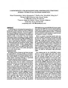
conform to the routing choices in R uni . Furthermore, if DGuni is free from cycles, it provides a deadlock-free reconfiguration path between DG��old and DG��new through the use of adding and removing phases. The conceptual relationship between the channel dependency graphs of routing functions as described above is illustrated in Figure 1; Table 1 summarizes the notation used. From these notions, some very important definitions that relate two routing functions are asserted below. Definition 1 Two routing functions Ra and Rb are said to be conforming (or a conforming pair) if for at least one of the routing functions, all of the channels it supplies are also supplied by the other routing function. For two conforming routing functions R a and Rb , the routing function given by Ra ∩ Rb is referred to as the reduced routing function, and the one given by R a ∪ Rb is referred to as the extended routing function. Each of these routing functions (reduced and extended) are either equal to Ra or Rb . Definition 2 A routing function R is said to be maximally extended (denoted by R � ) if it can supply 6
DGold
DG’’old
DGnew
DG’’new
DGold DGnew DG’new DGuni DGint Figure 1. Illustration of relationship between channel dependency graphs. For compatible routing functions Rold and Rnew (left), add → DG�old →remove → DGint →add → DG�new →remove → DGnew . transition phases are DGold → DG’old
The depiction on the right is the dual case of the one on the left. For dual compatible routing functions, transition phases are
DGold →remove → DG��old →add → DGuni →remove → DG��new →add → DGnew .
Note that the amount to
which the original dependency graphs can be extended (or reduced) may vary, depending on the particular routing function and choice of routing options added or removed.
Routing function
Dependency graph
Description
Rold
DGold
The old routing function and its dependency graph
Rnew
DGnew
� Rold
DG�old
� Rnew
DG�new
Rint
DGint
The new (final) routing function and its dependency graph. A maximal cycle free extension of DG old and a routing function that has DGold as dependency graph. A maximal cycle free extension of DG new and a routing function that has DGnew as dependency graph. The routing function and dependency graph emerging from the intersection between DG�old and DG�new
�� Rold
DG��old
A minimal connected sub-graph of DG old and its routing function.
�� Rnew
DG��new
A minimal connected sub-graph of DG new and its routing function.
Runi
DGuni
The union of DG ��old and DG��new and its routing function.
Table 1. Notation used to represent routing functions and channel dependency graphs.
no other channel without closing a dependency cycle in its dependency graph DG. Likewise, a routing function R is said to be minimally reduced (denoted by R �� ) if no other channel can be removed from the set that it supplies without disconnecting the routing function. Definition 3 Two routing functions Ra and Rb (likewise, their extended versions) are said to be compatible if a connected routing function R int can be found from the intersection of the two routing functions or from the intersection of any combination of their extended versions up to their maximal extensions Ra� and Rb� . Note that Rint conforms to these routing functions and could be equivalent to one of them. If such a connected and conforming routing function does not exist, the two routing functions (likewise, their extended versions) are said to be incompatible. Definition 4 In the dual case, two routing functions R a and Rb (likewise, their minimal versions) are said to be dual compatible if a deadlock-free routing function R uni can be found from the union 7
of the two routing functions or from the union of any combination of their reduced versions down to their minimal reductions R a�� and Rb�� . The (reduced) routing functions, which are conforming to Runi , are said to be coexisting (or coexistent) since they can coexist in a deadlock-free manner. If such a deadlock-free routing function does not exist, the two are said to be dual incompatible. Definition 5 A reconfiguration process is said to be persistently deadlock-free if the prevailing routing function remains deadlock-free at any step, where a step is an atomic update to one or more local routing functions. Our aim is to have reconfiguration processes be derivable from a simple and straightforward methodology in which the following sufficient conditions for deadlock-free reconfiguration—as given by the main lemma below—are upheld. This lemma is derived from the stronger theorem and first corollary given in [1]. We will show exactly how these conditions can be upheld in most cases in later sections. Sufficient Conditions for Deadlock-free Reconfiguration: 1. The prevailing routing function is connected and deadlock-free at all times. 2. During an Adding Phase, no routing choice may be added to any switch that closes a cycle of dependencies on escape resources. 3. During a Removing Phase, no routing choice may be removed from any switch before it is known that there will be no packet needing this routing choice—either to proceed or to enter escape resources. 4. All potential ghost dependencies are removed from the network before a transition from a Removing Phase to an Adding Phase. Note that condition 4 requires a barrier synchronization between a removing phase and an adding phase. This is most easily implemented as part of the drainage algorithm. One way of doing this is explained in the Appendix. Lemma 1 A reconfiguration process derived from a sequence of atomic phases of adding and removing zero or more routing choices in each phase is deadlock-free if all four conditions above are satisfied. (A full formal proof using the theory in [1] is provided in the Appendix.)
8
Proof Sketch: We can prove Lemma 1 by considering all cases separately: the Adding Phase, the Removing Phase, and the transitions between these two phases. Assume the prevailing routing function at the start of any phase is connected and deadlock free (1st condition). Throughout an adding phase, no deadlock can form as the escape path remains deadlock-free (2nd condition), and there can be no ghost dependencies—these would have been there at the start of that phase but are eliminated by the 4th condition. As routing choices may only be added to an already connected routing function, the prevailing routing function remains both connected and deadlock free. These properties remain over the transition from an adding phase to a removing phase. Throughout a removing phase, the configuration of packets in the network at any time is allowed by the routing function that prevailed at the beginning of the phase. Since the 3 rd condition guarantees that no routing choice is removed before we know that it is no longer needed, no packets will be rendered unroutable by the network (thus blocking other packets) and the escape path will not be destroyed by the removal of a routing choice (i.e., it remains intact). This remains over the transition from a removing phase to an adding phase. As the prevailing routing function remains connected and deadlock-free throughout all phases, the reconfiguration process is persistently deadlock-free.
3 The Design Methodology In this section, we present a global view of the methodology, analyze the possible cases that may arise in practice, and show how the methodology addresses each of them. How the sufficient conditions for deadlock-free reconfiguration are satisfied is also considered. The descriptions in this section are intentionally informal, aiming at providing a global view of the different strategies that can be used in each case and their relationship. Therefore, this section also provides pointers to the various sections where each case is analyzed in more detail. The gist of the methodology is the following. Reconfiguration processes in their most rudimentary form can be derived from a sequence of conforming pairs of routing functions. The transition between two conforming routing functions is done through atomic phases of either adding zero or more routing options (i.e., Adding Phase) or removing them (i.e., Removing Phase). For the simplest cases, reconfiguration is done between coexisting routing functions or between compatible (or dual compatible) routing functions using an appropriate sequence of at most four conforming pairs of routing functions. For some cases in which compatibility may be undetectable 9
or non-existent (i.e., incompatible or dual incompatible routing functions), reconfiguration processes may be derived using an appropriate sequence of more than one pair of (dual) compatible routing functions where each (dual) compatible routing function in the sequence is reached via an appropriate sequence of at most four conforming pairs of routing functions. For all cases, the properties of coexistence and (dual) compatibility conveniently ensure that all four sufficient conditions in Lemma 1 are upheld, and forward progress toward the new routing function is always made. For other cases in which compatibility may be undetectable or non-existent, forward progress may be stalled since a connected (alternatively, cycle-free) conforming routing function may not exist along appropriate sequences between the old and new routing functions. In these particular cases, selective halting of packet injection may be used to relax part of the 1 st condition, i.e., allowing the prevailing routing function not to be connected at the start of a phase. Only those packets needing the reconfiguration-induced disconnected region of the network are prevented from being injected; all others continue to be allowed into the network and are routed normally. Below, we outline the methodology in greater detail for all the practical cases that may arise when dynamically reconfiguring from an initial routing function, R old , to a final one, Rnew . Case 1: The simplest case occurs when Rold and Rnew are coexisting routing functions. In this case, Rold ∪Rnew does not contain any cycle in its channel dependency graph and, thus, is obviously deadlock-free and connected. In this case, the transition from Rold to Rnew poses no problem. Two sub-cases arise. First, if Rold ∪ Rnew = Rold or Rnew , the two are a conforming pair—in which case, if Rold is the extended routing function, routing options are removed until R new is reached; otherwise, routing options are added until R new is reached. Second, if Rold �= Rold ∪ Rnew �= Rnew , routing options from Rnew are first added to Rold until it is made equal to R old ∪Rnew (the extended conforming routing function), then routing options are removed until it is made equal to R new . Note that a sequence of at most two conforming pairs of routing functions are needed, which happen to be connected and deadlock-free at all times. Case 2: An equally simple case occurs when Rold ∩ Rnew is connected. This is the dual of Case 1 above and is the simplest case of compatibility between R old and Rnew when they are nonconforming pairs. Obviously, R old ∩ Rnew does not contain any cycle in its channel dependency graph because Rold and Rnew are deadlock-free. Again, the transition from Rold to Rnew poses 10
no problem. As with Case 1, two sub-cases arise. First, if R old ∩ Rnew = Rold or Rnew , the two are a conforming pair: if Rold is the reduced routing function, routing options are added until Rnew is reached; otherwise, routing options are removed until R new is reached. Second, if Rold �= Rold ∩ Rnew �= Rnew , routing options from Rold that are not in Rnew are first removed from Rold until it is made equal to R old ∩ Rnew , then routing options are added to R old ∩ Rnew until it is made equal to Rnew . Again, note that a sequence of at most two conforming pairs of routing functions are needed, which happen to be connected and deadlock-free at all times. Cases 1 and 2 present two basic reconfiguration primitives: transition between two routing functions via an intermediate conforming routing function made either by an adding phase possibly followed by a removing phase or by a removing phase possibly followed by an adding phase. Most of the remaining cases are handled by using a sequence of either of these two primitives. Case 3: The next case in increasing order of complexity occurs when Rold and Rnew are compatible but Rold ∩ Rnew is not connected. As described in the previous section, this case is handled by first adding routing choices to Rold without introducing cycles in its channel dependency graph. � � � � The extended routing function Rold is such that Rint = Rold ∩ Rnew is connected, where Rnew is � through an adding phase from Rold , a removing a suitable extension of Rnew . After reaching Rold
phase is performed in such a way that Rint is obtained. This is followed by another instance of � adding and removing phases, which lead to R new and Rnew , respectively. � � � � = Rold ∪ Rint and Rnew = Rnew ∪ Rint , and both Rold and Rnew It should be noted that Rold
have no cycles in their respective channel dependency graphs. Thus, the strategy followed in this case can be viewed as a sequence of two Case 1 steps consisting of at most four pairs of conforming routing functions. In the first one, an adding and a removing phase is implemented in order to reach Rint (which is compatible with Rold as well as with Rnew ). In the second one, another instance of an adding and a removing phase is implemented in order to reach R new . Case 4: The dual of Case 3 occurs when it is possible to find two connected reduced routing �� �� �� functions Rold and Rnew such that Rold supplies a subset of the routing options provided by R old , �� �� �� Rnew supplies a subset of the routing options provided by R new , and Runi = Rold ∪ Rnew does not
contain any cycle in its channel dependency graph—that is, R old and Rnew are dual compatible. In this case, it is obvious that the sequence of steps should be the dual of the sequence used in Case 11
�� 3. First, a removing phase is required to reach Rold , followed by an adding phase to reach Runi ; �� then, a removing phase is required to reach Rnew , followed by an adding phase to reach Rnew .
It should be noted that Case 3 may occur when Rold and Rnew can be extended to provide additional routing options without closing any cycle in their channel dependency graph. This is usually the case when both Rold and Rnew are minimally connected—that is, they provide the minimum number of routing options to guarantee connectivity (e.g., dimension-order routing in n-dimensional meshes). However, the strategy proposed in Case 3 does not work when R old and Rnew are such that adding a single routing option anywhere in the network will close a cycle in the corresponding channel dependency graph (e.g., up*/down* routing [13]). On the other hand, the strategy proposed in Case 4 does not work for minimally connected routing functions but may work for routing functions that provide several options for each message destination (e.g., [25]). Case 5: When compatibility between Rold and Rnew is undetectable or non-existent, two adding and two removing phases are no longer enough to move from R old to Rnew while keeping the prevailing routing function connected and deadlock-free at all times. In this case, the strategy to follow consists of finding a sequence of intermediate connected and deadlock-free routing functions such that each one guarantees the compatibility or dual compatibility between the previous intermediate routing function and the next one. Obviously, the first intermediate routing function should guarantee the compatibility or dual compatibility among R old and the second intermediate routing function. A similar condition is required for the last intermediate routing function with respect to Rnew . Also, intermediate routing functions should be such that forward progress toward Rnew is done from one intermediate routing function to the next one—that is, each intermediate routing function removes some routing options from R old and/or adds some routing options from Rnew with respect to the previous one. This is referred to as a progressive step-by-step approach. Case 6: When compatibility between Rold and Rnew is undetectable or non-existent and there is no sequence of intermediate routing functions implementing a progressive step-by-step dynamic reconfiguration, it may still be possible to follow a non-progressive approach. In this case, the approach is similar to the one for Case 5—that is, finding a sequence of intermediate connected and deadlock-free routing functions such that each one guarantees the compatibility or dual compatibility among the previous intermediate routing function and the next one. However, in this case, 12
a point is reached where it is not possible to make constant forward progress. In particular, if we denote the prevailing intermediate routing function at step k as R k using either the compatible or dual compatible reconfiguration primitive, it is not possible to remove from R k any routing option that is in Rold but not in Rnew without disconnecting Rk , and it is not possible to add to R k any routing option that is in R new but not in Rold without closing a cycle in the channel dependency graph for Rk . Therefore, it is necessary to backtrack instead of always making forward progress. In other words, when computing the next intermediate routing function, some routing options that are in Rnew are removed from Rk without disconnecting it. Obviously, those routing options will have to be added in a later step, but their removal at the current step re-enables forward progress to be made from the current step by adding other routing options that are in R new without closing a cycle in the channel dependency graph for Rk . Several detours may be necessary, but as forward progress is always (re)enabled, reconfiguration is guaranteed to complete. This approach is referred to as detoured step-by-step dynamic reconfiguration. Case 7: Finally, when compatibility between R old and Rnew is undetectable or non-existent and there is no sequence of intermediate routing functions implementing a step-by-step dynamic reconfiguration (neither progressive nor detoured), it is still possible to perform dynamic reconfiguration, but in a somewhat degraded manner. The degradation comes from the fact that part of the network will either become disconnected or will contain cycles in the channel dependency graph for the prevailing intermediate routing function at some point during the reconfiguration. Obviously, among these two options, we select disconnectivity because it is less dangerous than the risk of deadlock. Hence, if part of the network becomes disconnected at some step during the reconfiguration process, the 1st condition in Lemma 1 no longer holds. The consequence of this is that some pairs of nodes will be unable to communicate due to the lack of connectivity among them. This situation can be handled by selectively halting the injection of packets for which the prevailing routing function currently supplies no path toward their destination. Injection will be halted for as short a time as possible, but it definitely has the potential to degrade performance. Anyway, this is still much better than halting the injection of all packets in the entire network during the whole reconfiguration process, as is done with static reconfiguration. Overall, the methodology in this case should also deliver a sequence of steps similar to one of the previous cases, the only difference 13
being that injection is halted in part of the network (and only for some source-destination pairs) during some of the steps. This approach is referred to as selective halting dynamic reconfiguration. The previous analysis considers all the cases that may arise when trying to derive a dynamic reconfiguration process between two routing functions, all of which are handled by the proposed methodology. In the following sections, we give details for the most relevant cases. In particular, the complex cases of compatible and dual compatible routing functions (Cases 3 and 4) are further discussed in Section 4, with some relevant examples. The case for incompatible routing functions is covered in further detail in Section 5, which includes both the cases for progressive and detoured step-by-step dynamic reconfiguration (Cases 5 and 6). Section 6 discusses the case when injection must be halted at some nodes to deal with the lack of connectivity (Case 7), also presenting a representative example. As Cases 1 and 2 are trivial, they are not explicitly covered in further detail, although instances of these occur implicitly within other cases. Finally, in Section 7, we describe a heuristic algorithm useful for testing (dual) compatibility between routing functions and for finding their extensions (reductions). This allows for automated mapping of old and new routing functions to the various cases to which they belong for the appropriate actions to be followed.
4 Compatible and Dual Compatible Routing Functions 4.1 Compatible Routing Functions We first apply the methodology to Case 3 in which the old and new routing functions are compatible but Rold ∩ Rnew is not connected. In this case, we know that there exists a connected and deadlock-free routing function, namely Rint , that conforms to both the extended versions of Rold and Rnew without closing cycles of channel dependencies. Therefore, the transition between Rold and Rnew can be done in two main steps: first, transition from R old to Rint , and then transition from Rint to Rnew . The transition between routing functions for each step is done using the basic reconfiguration primitive of an adding phase followed by a removing phase (i.e., Case 1). Reconfiguration processes can be derived as described below. R ECONFIGURATION P ROCESSES FOR C OMPATIBLE ROUTING F UNCTIONS : First Adding Phase: Asynchronously add the new routing choices of Rint to all switches. First Removing Phase: Following the order of the channel dependency graph DGold , wait until there are no packets in each channel needing the routing choices of Rold that are not in Rint , then remove these routing choices from the switch to which this channel delivers packets. 4 4
In reference to the theory presented in [1], removing phases act to filter out unwanted ghost dependencies, i.e., in
14
Second Adding Phase: Wait until there are no potential ghost dependencies in the system (i.e., wait until all the switches complete the first removing phase), then asynchronously add the new routing choices of Rnew . Second Removing Phase: Following the order of the channel dependency graph DGint , wait until there are no packets in each channel needing the routing choices of Rint that are not in Rnew , then remove these routing choices from the switch to which this channel delivers packets. 5 Note that the method we have given for reconfiguration between compatible routing functions does not require any traffic source to stop injecting packets into the network at any time nor does it result in the premature removal of routable packets from the network before reaching their destinations. As other channels can be used to route packets, the halting of packet injection into drained channels does not result in the overall halting of packet injection by sources—injection can still take place into those alternatively supplied channels from the adding phases. Reconfiguration is therefore dynamic and deadlock-free. Also, as connectivity and deadlock freedom are maintained throughout, no packet dropping is required on account of reconfiguring the routing function. Below, we provide two specific applications of our methodology for this case of compatible routing functions. In the first, a new and previously unknown dynamic reconfiguration process is derived; in the second, a version of the previously proposed Double Scheme [23] dynamic reconfiguration technique is derived. These examples show the power and simplicity of the proposed methodology and also serve to verify its validity. Example 1: Consider a mesh topology, as shown in Figure 2, that uses YX dimension order routing— that is, first route in the Y dimension and then route packets in the X dimension to reach their destination. Assume that we would like to dynamically reconfigure the routing of this topology into XY routing instead. We have depicted the channel dependencies of DG old (YX routing) in the form of allowable turns6 between consecutive network channels in the upper row of Figure 3. To continue along a dimension, note that zero degree turns are allowed. The channel dependencies of DGnew (XY routing) are depicted in the middle row of Figure 3 in the form of allowable turns. this case, through the use of negative CND-tuples expressed here as R old routing choices that are not in R int . 5 A detailed discussion of one of possibly many techniques for implementing the channel drainage needed in the removing phases is included in the Appendix. 6 Dimensional turns for a 2-D mesh are enumerated from 1 to 8 in the figure.
15
We show that the old and new routing functions are compatible, allowing us to find a DG int whose channel dependencies are depicted in the lower row of Figure 3.
CA-0
C01
0
C03
C12
1
C10
C30
I
C14
2
C21
C41
C25
CA-2
C34
3
C36
C63
C45
4
C43
C47
C74
C58
6
C67 C76
7
C78 C87
R
I
0 0 R
C01
C10 I
1 1
C12
C25
C03
C14
C41
C52
C30
C41
C34
C43
R
4 I
5 R
I C45
3 3 I R
R
C34
C43 I
4 4
I
C52 5 5 I R C45
C47
C58
C36
C63
C74
C85
C63
2 2 R C25
R
C54
C36
C21
R
C30
CA-5
C54
C47
C58
y
C85
7
6 8
2 I
C14
3
x CA-6
C21
R
C03
C52
5
C54
C12
1 I
R
I CA-3
C10
C01
0
CA-1
CA-4
CA-8
I
I
R C67
C74
8 R
C76
I C78
C87
R
I
6 6 R
C85
I C67
C76
7 7
R
I C78
8 8 R
C87
CA-7
(b) DG old = YX
(a) 3 x 3 mesh N I
Figure 2. (a) A
Rnew = XY
3 × 3 mesh network routing.
R
(c) DG new = XY
Injection/Reception Channels at node N Network channel
and corresponding channel dependency graphs for (b)
DGold
Rold = Y X
routing and (c)
Additional dependencies in DG’old
4
7
3
6
1
5
DGnew
Additional dependencies in DG’new
8
3
7
2
5
1
DGint
3
7
5
1
� � Figure 3. Dependencies allowed in the channel dependency graphs of Rold , Rold , Rnew , Rnew , and Rint , respectively. Dependencies between channels are shown as allowable turns.
In constructing an extended DG�old , we can safely add dependencies from left-up and left-down turns (turns 3 and 5) to DGold , shown on the upper right-hand side of Figure 3. There are no cycles of dependencies in the clockwise direction in DG �old since there are no dependencies making a right-down turn (turn 2). Furthermore, there are no cycles in the counterclockwise direction because the right-up turn is prohibited (turn 8). Thus, DG �old is cycle-free. Nevertheless, if any other turn were added to DG�old , the graph would not remain cycle-free. Hence, this is the maximum extent to which the graph can be extended in this manner. The corresponding routing function for this graph happens to be East Last (EL) Turn Model routing [25] (Figure 4(a)). In constructing DG�new , we may add up-right and down-right dependencies and establish the cycle-free properties of an extended dependency graph in an analogous way. These turns (turns 1 and 7) are shown on the righthand side of the middle of Figure 3. Prohibited turns for this graph 16
C01
0 I
C10
C12
1 I
R
C21
R
2 I
R
C01
0 I
C03
C14
C25
C30
C41
C52
C10
3
C34
4
C43
R
I
I C45
C36
C34
3 I
C54
R
I
7 I
R C67
I C45
C76
I C78
C87
C41 C34
C43
R
I
I
R
C36
C47
C63
C74
8 R
C76
I C78
I R
R
C52 5
R
I
R
C54 C58
C85 7
I
R C67
C87
(b) DG’ new = West First I
R
C25
4 I
6
N
� Figure 4. Dep. graphs for (a) Rold
C85 7
6 C67
(a) DG’ old = East Last
C14
C45 C58
C74
R
2 I
R
C54
C47
C63
8 R
C21
R
C30 I
C85
6 I
C52
R
C12
1 I
C03
5
C58
C74
C25
4
C10
R
3
C43
C36 C63
I R
C41
R
C47
2 I
C14
C30
5 R
C01
0
C21
R
C03
I
C12
1 I
R
C76
8 R
I C78
R
C87
(c) DG int = Hybrid YX/XY
Injection/Reception Channels at node N Network channel
� = East Last, (b) Rnew = West First, and (c) Rint = Hybrid: Y ±X+/X-Y ±.
are down-left and up-left turns (turns 4 and 6), resulting in a cycle-free DG�new . The corresponding routing function for this happens to be West First (WF) Turn Model routing [25] (Figure 4(b)). The intersection of the channel-tuple sets for DG�old and DG�new allow us to construct DGint , depicted in the lower row of Figure 3. and shown in Figure 4(c). Clearly DGint is connected and gives rise to a Hybrid YX/XY routing function R int in which packets going rightwards (i.e., in the X+ direction) use YX routing and those going leftwards (i.e., in the X- direction) use XY routing (i.e., Hybrid Y ±X+/X-Y ±). Consequently, the routing choices supplied by R int are a subset of those supplied by EL routing and WF routing. Using the above, our methodology allows us to derive the following new and previously unknown, dynamic reconfiguration algorithm consisting of two adding and two removing phases. A N EW DYNAMIC R ECONFIGURATION P ROCESS
FOR
YX
TO
XY ROUTING :
To streamline the description, the table below indicates the routing functions that prevail between each phase and the changes that must take place in the preceding adding or removing phase: Routing function
Allowed turns
Changes
1
Rold (Y X)
1,4,6,7
2
� Rold (East Last)
1,3,4,5,6,7
(+3, +5)
3
Rint (Hybrid: Y ±X+/X-Y ±)
1,3,5,7
(-4, -6)
4
� Rnew (West First)
1,2,3,5,7,8
(+2, +8)
5
Rnew (XY )
2, 3, 5, 8
(-1, -7)
Example 2: Another application of our methodology for reconfiguration between compatible routing functions leads to a version of the Enhanced Basic Double Scheme [23] applicable in this case to table 17
based virtual cut-through switched networks with regular or irregular topology. Here, we assume that there are two virtual channels associated with each physical channel. We group the virtual channels into global virtual networks, so that we have the notion of upper and lower layers—each layer corresponding to a distinct virtual network. Assume Rold supplies fully adaptive (cycle-prone) routes in the lower layer and cycle-free routes in the upper layer. Furthermore, assume packets can go from the lower layer to the upper layer and vice versa, using the upper layer as an escape layer with a deadlock-free routing subfunction, as described in [6]. Furthermore, no assumption is made on whether R new is compatible with Rold ; Rnew supplies adaptive routes in the upper layer and cycle-free routes in the lower layer in such a way that the lower layer becomes the escape layer (as opposed to the upper layer in R old ). Given the above, it can be proved that Rold and Rnew are always compatible. The basis of the proof comes from the fact that Rold can take on any extension in the lower layer without � , all turns generating deadlocks as long as the upper layer remains an escape layer. Thus, in R old � are allowed in the lower layer. Similarly, all turns are allowed in the upper layer in R new . The
intersection of the channel-tuple sets for the extended dependency graphs allows DG int to be constructed. The intersection causes it to contain dependencies only from DG new in the lower layer and dependencies only from DGold in the upper layer. Therefore, Rint is a routing function in which the lower layer is routed according to Rnew and the upper layer is routed according to Rold . Since the upper layer is the escape layer of Rold and the lower layer is the escape layer for Rnew , Rint must be connected and deadlock-free. This leads to a dynamic reconfiguration algorithm derived from our methodology that contains two adding and two removing phases. 7 4.2 Dual Compatible Routing Functions The two previous examples considered compatible routing functions. Here, we apply our methodology to Case 4 in which the old and new routing functions are dual compatible. With this, we know that there exists a connected and deadlock-free routing function, namely R uni , that conforms to both reduced versions of Rold and Rnew without closing cycles of channel dependencies. Therefore, the transition between Rold and Rnew can be done in two main steps: first, transition from Rold to Runi , and then transition from Runi to Rnew . The transition between rout7
A detailed description of the complete reconfiguration process is in the Appendix.
18
ing functions for each step is done using the basic reconfiguration primitive of a removing phase followed by an adding phase (i.e., Case 2). Reconfiguration processes can be derived as below. R ECONFIGURATION P ROCESSES
FOR
D UAL C OMPATIBLE ROUTING F UNCTIONS :
First Removing Phase: Following the order of channel dependency graph DGold , wait until there �� are no packets in each channel needing the routing choices of Rold that are not in Rold , then
remove these routing choices from the switch to which this channel delivers packets. First Adding Phase: Wait until there are no potential ghost dependencies in the system (i.e., wait until all the switches complete the first removing phase), then asynchronously add the new routing choices of Runi to all switches. Second Removing Phase: Following the order of channel dependency graph DGuni, wait until �� there are no packets in each channel needing the routing choices of Runi that are not in Rnew ,
then remove these routing choices from the switch to which this channel delivers packets. Second Adding Phase: Wait until there are no potential ghost dependencies in the system (i.e., wait until all the switches complete the second removing phase), then asynchronously add the new routing choices of Rnew . Example 3: In this example, we develop a process for reconfiguration between two Turn Model based routing functions for meshes, namely North First (NF) and North Last (NL). North First is characterized by having every turn into the north direction prohibited, so any packet that needs to go northwards must go in the north direction first. For North Last, all turns out of the north direction are prohibited, so every packet that needs to go northwards has to go in that direction last after all other directions have been used. Recall that the various turns for a 2-D mesh are depicted and enumerated in Figure 3. In North First routing, turns 3 and 8 are disallowed, whereas in North Last routing, turns 1 and 6 are disallowed. Clearly, North First and North Last are incompatible. They are both maximally extended, so no additional turns may be added without closing a cycle of dependencies. Furthermore their intersection is not connected—if there are no turns into nor out of the north direction, no packet can travel northwards. However, it can be shown that the two routing functions are dual compatible. �� Let the minimal subset of North First routing (i.e., R old ) be equal to Y X routing. Furthermore,
19
�� �� obtain Rnew from North Last by disallowing turns 2 and 5. It can now be easily verified that R new �� �� �� and Rold are connected. Furthermore, the union of Rnew and Rold results in South First Turn Model
routing, thus this union is clearly deadlock free. The following new reconfiguration process with two removing and two adding phases is, thus, correct (i.e., always connected) and deadlock-free. A N EW DYNAMIC R ECONFIG . P ROCESS F OR N ORTH F IRST Routing function
Allowed turns
Changes
1
Rold (North First)
1,2,4,5,6,7
--
2
�� Rold (Y X)
1,4,6,7
(-2, -5)
3
�� �� Rold ∪ Rnew (South First)
1,3,4,6,7,8
(+3, +8)
4
�� Rnew (Hybrid: X±Y +/Y -X±)
3,4,7,8
(-1, -6)
5
Rnew (North Last)
2,3,4,5,7,8
(+2, + 5)
TO
N ORTH L AST ROUTING :
5 (Dual) Incompatible Routing Functions 5.1 Progressive Step-by-step Reconfiguration Here, we address the progressive step-by-step approach described for Case 5 given in Section 3. Recall that the idea is that whenever two routing functions cannot be verified as either compatible or dual compatible, a sequence of intermediate routing functions that are either compatible or dual compatible is searched for. In the following, we describe an approach that aims at finding a sequence of compatible routing functions; the case for finding sequences of dual compatible routing functions when Rold and Rnew are dual incompatible is analogous. If Rold and Rnew are incompatible, then there exists no routing function R int that is connected � � and conforming to both of them nor with their maximally extended versions R old and Rnew . In this
case, a step-wise approach may be used in which, in each step k, an attempt is made to find an intermediate routing function Rk that is compatible with the routing function in the previous step and that is closer to Rnew than what Rold is. This intermediate routing function will, in turn, play the role of Rold in the next successive step. Example 4: One interesting application of progressive reconfiguration is when the configuration task at hand can be divided into a sequence of reconfigurations on subparts of the network. One such case is the reconfiguration of a three-dimensional mesh from dimension order routing in XYZ order 20
to routing in YZX order8 . This can be done by first, in two adding and two removing phases, reconfiguring each XY-plane so that each of them routes in YX order rather than XY. This part of the reconfiguration will (in each plane) be identical to a YX to XY reconfiguration which we have already described above, but done in the reverse direction. It results in dimension order routing in YXZ order. Then, in two consecutive adding and removing phases, reconfiguration is done in each XZ plane so that packets route in ZX order. This results in YZX routing over the entire cube. This example can be generalized as follows: In an n-dimensional mesh with dimension order routing, the YX to XY reconfiguration described previously can be used to swap any two dimensions that are adjacent in dimension order. Any total dimension order can therefore be reached by progressive step-wise reconfigurations, where each step swaps adjacent dimensions. In the above example, we were able to identify the intermediate routing functions in each step by using our knowledge of another reconfiguration process, i.e., the one described in Section 4.1. Sometimes, however, a sequence of intermediate routing functions is not known and must somehow be derived. Consider the methodology for compatible routing functions. Assuming that we do not detect compatibility, we will not be able to find a connected R int from DG�old and DG�new . In order to achieve connectivity for some Rint , we can extend DGint with dependencies (as few as possible) from DGold until connectivity is reached. Let us call this new dependency graph corresponding to this first intermediate step DG int1 and the routing function induced from it R int1 . � Obviously, DGint1 is a reduced version of DG�old , making Rold and Rint1 a conforming pair of � are a conforming pair). routing functions (we already know that Rold and Rold
Now, DGint1 may be extended with as many dependencies from DGnew as possible without creating cycles. Let us call this new dependency graph DGnew1 and the routing function derived from it Rnew1. Whenever a path from Rnew is allowed in Rnew1 , that path is supplied. Obviously, DGint1 is a reduced version of DGnew1, making Rint1 and Rnew1 a conforming pair of routing functions. These observations allow us to postulate the following: Lemma 2 Rold and Rnew1 are compatible. � (an Proof: This follows easily from the fact that R int1 is connected, and it is conforming with R old
extended version of Rold ) and with Rnew1 . 8
It can be shown that XYZ and YZX routing is compatible, thus this reconfiguration problem can also be solved through the approach described in Section 4.1. Nevertheless, we include this example here for illustration purposes.
21
Given Lemma 2 and the reconfiguration primitive defined for compatible routing functions, we are now able to approach Rnew from Rold by first transitioning to Rnew1 . This new routing function will be closer to Rnew than Rold is if at least one of the following two outcomes occur: • The set of dependencies that was added in order to make DGint1 connected left out some dependencies from DGold . Therefore, the number of dependencies that have to be removed in order to reach DGnew has been reduced. • There is at least one dependency from DGnew that could be added without creating a cycle in DGint1 . Therefore, the number of dependencies that remain to be added in order to reach DGnew has been reduced. The step above can now be repeated as many times as necessary. Every time an old dependency is removed in one step, it might open the possibility of adding a new dependency in the next step. In the same way, a dependency that is added in one step might allow the removal of an old dependency in a later step without losing connectivity of the intermediate routing function. Assuming that at least one of the two outcomes above always occurs at each step, the process is guaranteed to terminate and arrive at Rnew . The process above could lead to a successful conclusion or it could terminate at a step in which neither of the two outcomes mentioned occurs, thus no further progress toward R new would be possible. In this case, there are two possibilities. The first is that there is no sequence of adding and removing phases that take Rold closer to Rnew no matter what routing choices are added or removed. This case, which is Case 7, is treated in Section 6. The other possibility is that there exists a sequence of adding and removing phases taking Rold into Rnew , but this sequence may consist of some steps that require the removal of routing choices needed by the new routing function that must later be added or, alternatively, the addition of unnecessary routing choices that must later be removed. We saw this occur earlier in Example 3 for dual compatible routing functions, where turns 2 and 5 had to be temporarily removed and later added. In such cases, R new can be approached from Rold by taking some detours.9 In the next section, we consider the only case in which selective halting of injection of some 9
An example of a detoured reconfiguration process can be found in the Appendix.
22
packets into the network may be necessary, Case 7.
6 Selective Halting of Packet Injection For the final case in which no dependencies from Rold that need to be removed can be removed without loosing connectivity and none of the dependencies in R new that need to be added can be added without closing a cycle of dependencies, selective halting of packet injection can be used to ensure forward progress. That is, in order to proceed from a stalled state, a phase(s) is traversed in which either full connectivity cannot be supported or cyclic dependencies will form. We consider the problems of allowing a cyclic dependency graph even for a very short period of time to be too severe for this to be an attractive option. We therefore relax the condition of maintaining connectivity for a limited period of time. This is done by first removing some dependencies d rem , and then inserting new ones dadd . It must, however, be ensured that even if connectivity is lost when removing d rem , it must be reestablished when dadd has been added. Furthermore it must be guaranteed that after the addition of dadd , acyclicity of the dependency graph on escape resources is preserved. The proposed sequence of operations for finding drem and dadd is the following: 1. Start with empty drem and dadd . 2. Select one of the dependencies needing removal from DGold to reach DGnew ; add it to drem . 3. Add dependencies from DGnew that are not in DGold to dadd until (DGold \ drem ) ∪ dadd is connected. 4. If (DGold \ drem ) ∪ dadd is not cycle free on escape resources, go to step 2. Clearly the above procedure will make (DGold \ drem ) ∪ dadd approach Rnew . Since Rnew is connected and deadlock free, the procedure will terminate with sets d rem and dadd having the required properties. Hence, reconfiguration may proceed in the following way: 1. In the order of the current channel dependency graph, drain the network for packets using any dependency in drem . This will require injection links to stop injecting packets needing these dependencies. 2. When an input link to a switch is drained of these packets, remove routing table entries that are no longer needed (i.e., those in drem ). 23
3. When all required input links to a switch have been drained, insert the new entries that let packets use paths containing dadd . 4. When the above has been performed for all switches, open the injection links for all packets. Although selective halting of packet injection is part of the methodology, its correctness and freedom from deadlock is considered too obvious to require a proof. We simply conjecture that a phase with selective halting of packet injection can be part of any reconfiguration process without interfering with Lemma 1. Example 5: Assume a network where five switches enumerated from 1 to 5 are arranged in a cycle. Assume also that the routing function is such that no packet traverses Switch 5. This would give a network and dependency graph DGold as illustrated to the left in Figure 5. This routing function is clearly connected, and since the channel dependency graph is free from cycles, it is also deadlock free. 2
3
1
2
4
55
Figure 5. Selective halting of packet injection.
3
1
2
4
55
3
1
4
55
drem contains the two dependencies crossing Switch 2 in the leftmost figure, whereas
dadd contains the two dependencies crossing Switch 5 in the rightmost figure.
In this figure the arrows indicate a transition from
an input channel to an output channel over a switch according to the routing function. To avoid cluttering of the figure we have not illustrated the fact that each link contains two channels in opposite directions. However, through observing that there cannot be any dependency from a channel in one direction to a channel in the opposite direction around the cycle, the channel dependency graph should be easily assessed.
Now we would like to change the routing function into one where packets can traverse Switch 5, but where they cannot traverse Switch 2. The dependency graph DGnew for this routing function are illustrated to the right in Figure 5. None of the dependencies crossing Switch 5 can be added to DGold without closing a cycle. Furthermore, no dependencies in DG old can be removed without loosing connectivity. Now let us follow the approach described above for finding d add and drem. First we put the dependency crossing Switch 2 in the clockwise direction into d rem . In order to regain connectivity, 24
the dependency crossing Switch 5 in the counter-clockwise direction must be added to d add . The result of removing drem from DGold and then adding dadd is now connected but not deadlock free. Therefore we have to put the dependency that crosses Switch 2 on the counter-clockwise direction into drem as well. Now dadd can be enriched with both dependencies crossing Switch 5, and the procedure terminates with dadd and drem having the required properties. The reconfiguration method now requires us to selectively halt injection of packets into Switches 3, 4, and 5 that cross Switch 2. When these packets have been drained from the network, we know that the dependency in drem has been removed. After updating of the routing tables and introducing the new dependencies across Switch 5, the restriction on injection of packets can be lifted again. The resulting reconfiguration process is that illustrated in Figure 5. It should be noted that this simple example is a very important one since most topologies can be viewed as a set of linked and/or nested cycles. Indeed, reconfiguration in a cycle is the basic reconfiguration primitive used in some previously proposed dynamic reconfiguration schemes (e.g., PPR [20]).
7 Automating the Methodology The proposed methodology takes the old and new routing functions as inputs and generates a dynamic, deadlock-free reconfiguration process as output. If the union of the old and the new routing function is deadlock free (Case 1) or the intersection between them is connected (Case 2), then reconfiguration can be done in at most one adding and one removing step. If the old and the new routing functions are (dual) compatible, the reconfiguration can be done in at most two adding and two removing steps using an intermediate routing function. If compatibility is undetectable or non-existent, the new routing function may be approached step-wise by either removing dependencies that are not allowed by the new routing function or introducing dependencies that are required in the new routing function, or both. In some cases where this fails, it will be necessary to temporarily halt injection of some packets. These are the cases in which no routing function can be found that is both closer to the new routing function and compatible with the current one. In order to implement the actions prescribed by our proposed methodology, it is necessary to map routing functions appropriately to the various possible cases identified. In addition to testing for (dual) compatibility between R old and Rnew , it may also be necessary to test for (dual) 25
compatibility between two intermediate routing functions R int i and Rint
j
along some sequence
of steps composing the reconfiguration process. The main difficulty lies in the fact that there are, in general, many ways to extend DGold and DGnew into DG�old and DG�new to search for a connected intersection DGint and, thereby, establish compatibility. In the same way, there may be many ways to reduce DGold and DGnew into DG��old and DG��new to search for a deadlock-free union DGuni so that dual compatibility can be established. For networks of moderate size (or for networks with a repetitive structure where the repetition pattern is of moderate size), it is possible to do an exhaustive search through computer simulation. For large networks, however, this might not be feasible due to combinatorial explosion of the number of possibilities. In those cases, we suggest an heuristic to construct DGint or DGuni directly through an automated process. It is possible to search for DGint by starting with the intersection between DG old and DGnew . For as long as this intersection remains unconnected, the heuristic selectively adds to both DG old and DGnew the dependencies that are necessary to make DGint connected while keeping their extended versions DG�old and DG�new deadlock-free. This process will either succeed with a connected DGint —in which case DGold and DGnew are compatible—or it will fail in that no more dependencies can be added without creating cycles in either DG�old or DG�new —in which case we might still have compatibility, but the heuristic fails to detect it. Conversely, for DG uni, we start with the union of DGold and DGnew . For as long as this union is not cycle free, the heuristic selectively removes from DGold and DGnew dependencies that will make DGuni cycle free while keeping their reduced versions DG��old and DG��new connected. This will either succeed with a cyclefree DGuni —in which case DGold and DGnew are dual compatible—or it will fail in that no more dependencies can be removed without disconnecting either DG ��old or DG��new . The effectiveness of the above heuristic depends upon some choices of significance. The choice of which dependencies to add (or remove) from DGold and DGnew , for example, will decide whether an existing (dual) compatibility will actually be found. Although not guaranteed to detect (dual) compatibility for any given set of choices (i.e., in every instance), the proposed heuristic can detect compatibility given the right set of choices. Hence, the heuristic is not a limitation in and of itself. The following lemmas ensure that all examples provided in this paper are findable with the proposed heuristics. 26
Lemma 3 Assume that DGold and DGnew are compatible. Then there exist choices by which this compatibility can be detected by the above heuristics. Proof: If DGold and DGnew are compatible then there exist cycle free extensions DG�old and DG�new whose intersection DGint is connected. If the heuristic chooses to add to DG old and DGnew exactly those turns in DGint that they lack, they will clearly end up in a situation where their intersection will be exactly DGint , thus the compatibility is detectable. Lemma 4 Assume that DGold and DGnew are dual compatible. Then there exist choices by which this dual compatibility can be detected by the above heuristics. Proof: If DGold and DGnew are dual compatible then there exist connected subgraphs DG ��old and DG��new whose union DGuni is cycle free. If the heuristic chooses to remove from DGold and DGnew exactly those turns that are not in DGuni , they will clearly end up in a situation where their union will be exactly DGuni, thus the dual compatibility is detectable. Given the above heuristic, a complete algorithm that implements the proposed methodology for deriving dynamic deadlock-free reconfiguration processes between any two arbitrary routing functions can be defined. This is given in Figure 6 below. Our straightforward test-implementation of the heuristics was without guidance and in reasonable time able to find the intermediate routingfunctions that have been used in the examples throughout the paper.
8 Conclusions and Future Work In this paper, we have proposed a simple yet powerful methodology for deriving procedures for dynamic and deadlock-free reconfiguration between routing functions. This methodology puts no requirements on the type of routing function, switching technique, network topology, nor virtual network layering capability. It is capable of generating new and previously unknown reconfiguration processes as well as straightforwardly reproducing previously proposed processes. To our knowledge, this is the first completely general methodology for developing deadlock-free, dynamic reconfiguration processes proposed in the literature and is consistent with the theory described in a related paper [1]. The proposed methodology generates a step-wise approach for reaching a new routing function starting from an initial one. In the course of the development, the new notions of compatibility 27
if DGold ∪ DGnew is cycle free: [CASE 1]; done if DGold ∩ DGnew is connected: [CASE 2]; done else % the following code checks for Case 3 (compatible) let DG�int = DGold ∩ DGnew , let DG�old = DGold and let DG�new = DGnew while ((DG�int not connected) and (exists unexplored turn T ∈ / DG �int that makes neither DG �old nor DG�new cyclic)): add T to all of DG�int and DG�old and DG�new if (DG�int connected): [CASE 3] Reconfigure from DG old to DG�old to DG�int to DG�new to DGnew ; done else % the following code checks for Case 4 (dual compatible) let DG�uni = DGold ∪ DGnew , let DG��old = DGold , and let DG��new = DGnew while ((DG�uni not cycle free) and (exists unexplored turn T that closes a cycle in DG �uni and that can be removed from DG��old and DG��new without disconnecting them)): remove T from all of DG �uni and DG��old and DG��new % note that either DG��old or DG��new may not contain T if (DG�uni cycle free): [CASE 4]: Reconfigure from DG old to DG��old to DG�uni to DG��new to DGnew ; done else % the following code checks for the possibility of a progressive step (Case 5) using Case 2; remember that % at this point DG�old and DG�new are both maximally extended, but DG �int is still not connected while (DG�int not connected): add turn from DG old to DG�int if (DG�int different from DG old ): [CASE 5] Let a reconfiguration from DG old to DG�old to DG�int constitute one reconfiguration step; goto top of the algorithm letting DG �int play the role of DG old . % If this is the case, at least one turn from DG new that is not in DGold will be in DG�int , % or DG�int will lack a turn that was in DGold but not in DGnew , allowing forward progress to be made. else % the following code checks for the possibility of a progressive step (Case 5) using Case 1; remember that % at this point DG��old and DG��new are both maximally reduced, but DG �uni is still not cycle free while (DG�uni not cycle free): remove turn from DG �uni that closes a cycle in DG�uni and that exists in DGnew but not in DGold if (DG�uni different from DG old ): [CASE 5] Let a reconfiguration from DG old to DG��old to DG�uni constitute one reconfiguration step; goto top of the algorithm letting DG �uni play the role of DG old . % If this is the case, at least one turn from DG new that is not in DGold will be in DG�uni , % or DG�uni will lack a turn that was in DGold but not in DGnew , allowing forward progress to be made. else % here we did not find any way to get closer to DG new , so resort to Case 7 (Case 6 not used by heuristic) let drem and dadd be empty, and then add to d rem a turn T in DGold that is not in DGnew while ((DGold \ drem ) ∪ dadd not connected): add to d add a turn T � from DGnew that is not in DGold while ((DGold \ drem ) ∪ dadd not cycle free): [CASE 7] remove turns in d rem from DGold through halting of packet injection, add turns from d add , restart unrestricted packet injection, and continue from the top letting (DG old \ drem ) ∪ dadd play the role of DG old Figure 6. A heuristic algorithm for automated application of the proposed methodology.
28
and dual compatibility between routing functions are defined as well as the notions of conforming and coexisting routing functions. For routing functions that have the property of (dual) compatibility and for many cases of (dual) incompatible routing functions, the proposed methodology derives reconfiguration processes based on sequences of basic reconfiguration primitives which, themselves, have (dual) compatibility properties. For other types of (dual) incompatible routing functions, rudimentary sequences of conforming pairs of intermediate routing functions are used, possibly requiring in the worst case intermittent selective halting of packet injection. The power of the methodology lies in the fact that all possible cases of reconfiguration are handled simply and straightforwardly, and automated application of it is also possible. Future work may include a study of the relative frequency of (dual) compatibility between routing functions—in particular, in cases where R old is a routing function that works in the faultfree case, and Rnew allows all the surviving nodes to be connected in the presence of faults in the network. Another interesting problem is that of precisely defining—perhaps in a more automated way—possible sequences of intermediate (dual) compatible routing functions for (dual) incompatible routing functions and defining the conditions under which they can be known to exist with more precise heuristics. Currently, whenever such a sequence can be found, the methodology derives a reconfiguration process that can be used; however, in terms of efficient implementation of the methodology, it would be helpful to know early-on under which case (Case 1 - 7) the reconfiguration falls. Finally, the methodology assumes that out-of-order delivery of packets during reconfiguration is acceptable. It might be interesting to refine the methodology so that reconfiguration processes guaranteeing in-order delivery of packets might also be derived.
References [1] Jose Duato, Olav Lysne, Ruoming Pang, and Timothy Mark Pinkston. Part I: A Theory for Deadlock-free Dynamic Network Reconfiguration. In IEEE Transactions on Parallel and Distributed Systems, this issue. [2] P. Kermani and L. Kleinrock. Virtual cut-through: A new computer communication switching technique. Computer Networks, 3:267–286, 1979. [3] W. J. Dally and C. L. Seitz. Deadlock-free message routing in multiprocessor interconnection networks. IEEE Transactions on Computers, C-36(5):547–553, 1987. [4] W. J. Dally. Virtual-channel flow control. IEEE Transactions on Parallel and Distributed Systems, 3(2):194–205, March 1992. [5] J. Duato. A necessary and sufficient condition for deadlock-free adaptive routing in wormhole networks. IEEE Transactions on Parallel and Distributed Systems, 6(10):1055–1067, 1995.
29
[6] J. Duato. A necessary and sufficient condition for deadlock-free routing in cut-through and store-and-forward networks. IEEE Transactions on Parallel and Distributed Systems, 7(8):841–854, 1996. [7] J. Duato, S. Yalamanchili, and L. Ni. Interconnection Networks an engineering approach. IEEE Computer Society, 1997. [8] Kourosh Gharachorloo, Madhu Sharma, Simon Steely, and Stephen Van Doren. Architecture and design of AlphaServer GS320. ACM SIGPLAN Notices, 35(11):13–24, November 2000. [9] HP SC45 Team. The AlphaServer SC45 www.hp.com/techservers/systems/sys sc45 features.html.
Supercomputer:
Facts
and
Figures.
[10] W. Barrett et al. An overview of the blue-gene/l supercomputer. In Proceedings of the 2002 ACM/IEEE Conference on Supercomputing, CD ROM, November 2002. [11] David Garcia and William Watson. ServerNet TM II. Lecture Notes in Computer Science, 1417:119–135, 1998. [12] InfiniBand Trade Association. InfiniBand Architecture. Specification Volume 1. Release 1.0a. Available at http://www.infinibandta.com, 2001. [13] M. D. Schrder et al. Autonet: a high-speed, self-configuring local area network using point-to-point links. SRC Research Report 59, Digital Equipment Corporation, 1990. [14] N. J. Boden, D. Cohen, R. E. Felderman, A. E. Kulawik, C. L. Seitz, J. N. Seizovic, and Wen-King Su. Myrinet – a gigabit-per-second local-area network. IEEE MICRO, 1995. [15] Inc. Myrinet. Guide to Myrinet-2000 Switches and Switch Networks. www.myri.com, August 2001. [16] O. Feuser and A. Wenzel. On the effects of the IEEE 802.3x flow control in full-duplex Ethernet LANs. In IEEE, editor, LCN’99: proceedings: 24th Conference on Local Computer Networks: October 18–20, 1999, Lowell, Massachusetts, USA, pages 160–161. IEEE Computer Society Press, 1999. [17] Thomas L. Rodeheffer and Michael D. Schroeder. Automatic reconfiguration in Autonet. In Proceedings of 13th ACM Symposium on Operating Systems Principles, pages 183–197. Association for Computing Machinery SIGOPS, October 1991. [18] Dan Teodosiu, Joel Baxter, Kinshuk Govil, John Chapin, Mendel Rosenblum, and Mark Horowitz. Hardware fault containment in scalable shared-memory multiprocessors. In Proceedings of the 24th Annual International Symposium on Computer Architecture (ISCA-97), volume 25,2 of Computer Architecture News, pages 73–84, New York, 1997. ACM Press. [19] Aurelio Berm´udez, Rafael Casado, Francisco J. Quiles, Timothy M. Pinkston, and Jos´e Duato. On the infiniband subnet discovery process. In Proceedings of the International Cluster Computing Conference, December 2003. [20] R. Casado, A. Berm´udez, J. Duato, F. J. Quiles, and J. L. S´anchez. A protocol for deadlock-free dynamic reconfiguration in high-speed local area networks. IEEE Transactions on Parallel and Distributed Systems, 12(2):115–132, February 2001. [21] R. Casado, A. Berm´udez, F. J. Quiles, J. L. S´anches, and J. Duato. Performance evaluation of dynamic reconfiguration in high-speed local area networks. In Proceedings of the Sixth International Symposium on HighPerformance Computer Architecture, 2000. [22] N. Natchev, D. Avresky, and V. Shurbanov. Dynamic reconfiguration in high-speed computer clusters. In Proceedings of the International Conference on Cluster Computing, pages 380–387, Los Alamitos, 2001. IEEE Computer Society. [23] Timothy Mark Pinkston, Ruoming Pang, and Jose Duato. Deadlock-free Dynamic Reconfiguration Schemes for Increased Network Dependability. IEEE Transactions on Parallel and Distributed Systems, 14(8):780–794, August 2003. [24] O. Lysne and J. Duato. Fast dynamic reconfiguration in irregular networks. In Proceedings of the 2000’ International Conference of Parallel Processing, Toronto (Canada), pages 449–458. IEEE Computer Society, 2000. [25] C. J. Glass and L. M. Ni. The turn model for adaptive routing. Journal of the Association for Computing Machinery, 41(5):874–902, 1994.
30
Appendix for “Part II: A Methodology for Developing Deadlock-Free Dynamic Network Reconfiguration Processes” Olav Lysne, Timothy Mark Pinkston and Jos´e Duato 1 Formal Proof of Lemma 1 Using Theory in [1] The interested reader is referred to [1] for a definition of concepts and notation used in this proof. Large parts of this proof are based on the relation between two sets of CND-tuples. One set represents the set of all possible legal runtime states at a given instant in time of a reconfiguration process and is called the global set of legal CND-tuples at time T . The other set represents the set of possible legal runtime states allowed by the current routing function. This covers the states that the network could have been in if no reconfiguration occurred and the prevailing routing function had been there all the time. This is called the global set of legal CND-tuples with respect to the routing function R. A situation that may occur at some time T in a reconfiguration process is that the prevailing routing function R is deadlok free, but the global set of legal CND-tuples at time T is a superset of the global set of legal CND-tuples with respect to R so that the network is susceptible to deadlocking. The methodology proposed in this paper aims at avoiding such a situation. We start the proof by establishing some facts about the connection between these sets of CNDtuples at various points in a reconfiguration process. First, we consider the adding phase. Proposition 1 Let P be an arbitrary dynamic reconfiguration process that satisfies all four conditions, let T be an arbitrary point in an adding phase in P , and let R be the prevailing routing function at T . Then the global set of legal CND-tuples Θ T at time T is a subset of the global set of legal CND-tuples ΘR with respect to R. Proof: Let RS be the prevailing routing function at the start of the adding phase, and let Θ RS be the global set of legal CND-tuples with respect to R S . Condition 4 ensures that the global set of legal CND-tuples at the entrance of the adding phase is a subset of ΘRS . Since the adding phase only consists of adding routing choices we know that R S is contained in R, thus ΘRS ⊆ ΘR . Therefore, if there is a CND-tuple in ΘT that is not in ΘR , this must have been introduced by a routing choice outside of R between the start of the adding phase and T . Since the adding phase only consists of adding routing choices, we know that this is impossible. The next proposition handles the start of removing phases. Proposition 2 Let RS be the prevailing routing function at the start of a removing phase, and let ΘRS be the set of legal CND-tuples with respect to RS . Then the global set of legal CND-tuples at the start of this phase is a subset of Θ RS .
1
Proof: There are two cases: either this removing phase was the first phase in the reconfiguration, or it was preceded by an adding phase. In the first case, it follows trivially that the global set of legal CND-tuples at the start of the removing phase is a subset of Θ RS . If it was preceded by an adding phase, the start of this removing phase coincides with the end of the previous adding phase. In that case, the proof follows from Proposition 1. Finally, we consider the situation during a removing phase. Proposition 3 Let P be an arbitrary dynamic reconfiguration process that satisfies all four conditions, let T be an arbitrary point in a removing phase in P , and let R S be the prevailing routing function at the start of the removing phase containing T . Then the global set of legal CND-tuples ΘT at time T is a subset of the global set of legal CND-tuples Θ RS with respect to RS . Proof: From Proposition 2 we know that the set of legal CND-tuples at the start of the removing phase is a subset of ΘRS . During the removing phase routing choices are only removed, thus all routing decisions that can been made from the start of the removing phase until T are also allowed by RS . Therefore, no CND-tuples outside ΘRS can be introduced between the start of the removing phase and T , thus the proposition follows. Now we are ready to present the formal proof of Lemma 1 (we repeat the lemma below for ease of reading):
Lemma 1 A reconfiguration process derived from a sequence of atomic phases of adding and removing zero or more routing choices in each phase is deadlock-free if all four conditions stated in Section 2 are satisfied.
Proof: Let P be an arbitrary dynamic reconfiguration process that satisfies all four conditions. According to Corollary 1.1 of Theorem 1 in [1], we need to prove that for all legal runtime states T in P , where R is the prevailing routing function and Θ T is the set of legal CND-tuples at time T , there exists an escape channel set ∆ ⊆ DEP (R, ΘT ). We divide the proof into two cases, each one depending on whether T is in an adding phase or a removing phase. Case 1, T is in an adding phase: Let ΘR be the global set of legal CND-tuples with respect to R. Since R is free from deadlocks, we know that DEP (R, ΘR ) has an escape channel dependency set. If we can show that ΘT is a subset of ΘR , then DEP (R, ΘT ) must have the same escape channel dependency set. This follows from Proposition 1. Case 2, T is in a removing phase: Let ΘR be the global set of legal CND-tuples with respect to R. Furthermore, let RS be the prevailing routing function at the start of this phase, and let Θ RS be the global set of legal CND-tuples with respect to R S . The rest of the proof is by contradiction. Assume that the lemma is not true. Informally, this means that there must be a CND-tuple that is possible at time T which is not allowed according to the prevailing routing function R and whose corresponding packet cannot reach the escape 2
resources that R must have according to condition 1. More formally: there exists at least one CND-tuple < c� , c� , d >∈ (ΘT \ ΘR ) for which there does not exist c�� ∈ R(c� , d) such that < c� , c�� >∈ ∆ for some escape channel dependency set ∆ of DEP (R, ΘR ). From Proposition 3 we know that the problematic CND-tuple must have been allowed by the routing function at the start of the removing phase, that is, < c � , c� , d >∈ ΘRS . Furthermore, condition 1 says that a routing choice that would have allowed the packet whose header may reside in c� to enter the escape resources must have been in RS . Therefore, at some point during the removing phase, a routing choice must have been removed that deprived the packet whose header may reside in c� the possibility of moving into escape resources. This contradicts condition 3.
2 Implementation of Channel Drainage In the description of the methodology there are two issues for which we have not detailed out a solution. The first issue concerns how one can make sure that all potential ghost dependencies are drained from the system before the transition from a removing phase to an adding phase. The second problem regards the removing phase - how can one make sure that there are no more packets in the system that need an old routing table entry? Both of these questions regard drainage of the system of a certain class of packets. Assuming that we have solved the second problem, the first problem is easy: At the end of a removing phase we know that dependencies that are not part of the prevailing routing function will not be reintroduced. Therefore, the absence of ghost dependencies in a switch is a persistent situation once it has occurred, thus it suffices to let all switches report to a coordinating unit when they have no more ghost dependencies. We therefore only have to consider the problem of making sure that there are no more packets in the system that need an old routing table entry. Assume that we are entering a removing phase, and that we have a set of routing entries R rem that we want to remove. If the prevailing channel dependency graph is acyclic, and the prevailing routing function is connected, the removing phase can be implemented as follows. Let each injection link report to its attached switch that no packets that at some point will be routed according to Rrem will arrive. For each output link of each switch, do the following: 1. Wait until all input links from which the output link can expect traffic have reported that no more packets that at some point have been routed according to R rem will arrive. 2. Wait until there are no more packets in the input buffers of these input links that have previously been routed according to routing choices in R rem , then remove the routing entries from Rrem that are local to this output port. 3. Report on this output port that no more packets that had been routed according to R rem will be sent on this link. The reason why the end of the removing phase will be reached stems from a simple observation: The messages that indicate that no more packets having used R rem will arrive, will traverse all 3
channels in the order defined by the channel dependency graph. As this graph is acyclic, no channel will be visited twice, and thus, it consists of a finite number of steps. Also, as the prevailing routing function is connected, its channel dependency graph contains paths from every injection link to every reception link. Thus no report message will block forever in the network. Note that all of this happens while the network remains fully connected. The routing options that are removed in a removing phase are not necessary for connectedness. Therefore the draining process is independent of how the application uses the network, and end to end connections across the network can prevail while the draining of channels takes place. The barrier synchronization that is necessary between a removing phase and an adding phase can be implemented by letting all switches report to a coordinating unit that they have removed their subset of Rrem . This coordinating unit can in turn initiate the start of the adding phase. If the prevailing channel dependency graph is cyclic, however, the above algorithm will deadlock. All links along a cycle in the graph will forever be waiting for each other in step 1 above. The solution to this problem is to introduce a preprocessing step, where the active channel dependency graph is restricted to an acyclic one. In order to do this, we first observe that even if the routing function gives rise to a cyclic dependency graph, one may simply remove some routing choices from it and reach a connected routing function whose dependency graph is acyclic. Lemma A.1 In any connected and deadlock-free routing function that has cycles in its channel dependency graph, one may remove some routing choices from it and reach a connected and deadlock-free routing function whose dependency graph is acyclic. Proof: This is a consequence of a previous result in [2], that states that for an adaptive routing function to be deadlock free, there has to exist a connected routing sub-function whose channel dependency graph is acyclic. For proof detail, we refer to [2]. Let us denote this routing sub-function as R sub . The preprocessing step we propose is simply to instruct all switches to remove routing choices that are not in R sub . This step does not require any synchronization between switches because packets stored in any switch buffer will simply use routing options provided by R sub for the rest of their trip. Since Rsub is connected and does not give rise to cycles in the dependency graph, this preprocessing step will effectively reduce the prevailing routing function to one where the channel dependency graph is acyclic, hence the drainage algorithm described above can be used. Later on, the removed routing choices can be added back if their removal was only due to draining, not to reconfiguration. There are many potential ways to implement this preprocessing step. The fastest way would be to sweep the network in the reverse order of some spanning tree that is predefined. Each switch waits until its neighboring switches below it in the spanning tree are finished with their preprocessing step, then makes sure that no routing choices outside R sub are longer active before it informs its neighbor upwards in the spanning tree that it is finished with its preprocessing step. That way, the root of the spanning tree will, in time proportional to the maximum depth of the spanning tree,
4
know that Rsub is operational. Although the drainage algorithm is much more complex in the case of a cyclic channel dependency graph, we do not expect this to be a problem because this situation is rare. Indeed, R int is usually minimally connected by construction (or not connected, in case of incompatible R old and Rnew ), and this implies that its channel dependency graph is acyclic.
3 Dynamic Reconfiguration Process for Escape Layered Routing Functions 1. Add all the new routing choices of Rnew to the lower network layer. 2. Drain the lower network layer for packets needing the routing choices of R old that are not in Rnew by moving them to the upper network layer, then remove these routing choices from the switches in the lower layer as well as the transitions from the lower to the upper network layer. The routing function remains connected at all times, and there are no ghost dependencies by the end of this step. 3. Add all routing choices from Rnew to the upper network layer as well as the transitions from the upper to the lower network layer. 4. Drain the upper network layer for packets needing the routing choices of R old that are not in Rnew by moving them to the lower network layer, then remove these routing choices from the switches in the upper network layer. The routing function R new is now in operation.
4 An Example of Detoured Dynamic Reconfiguration In this example, we develop an alternative process for reconfiguration between North First (NF) and North Last (NL), which are incompatible. It will not be as efficient as the process described earlier that took advantage of the fact that these two routing functions are dual compatible. Nevertheless, we still choose to use this example as it clearly illustrates the methodology applied to the case of step-by-step detoured reconfiguration of incompatible routing functions when it may not be easily determined that they are dual compatible. Let us first demonstrate that progressively approaching North Last from North First (i.e., Case 5) is futile. Consider again the enumeration of turns shown in Figure 1. Starting from North First, the progressive approach prescribes a first step in which either or both turns 3 or 8 are added or turns 1 and/or 6 are removed. Since North First is already maximally extended, no turns can be added without closing a cycle of dependencies. Furthermore, the removal of turn 1 will make packets going to the north-east corner from the south-west of the mesh unroutable. Likewise, the removal of turn 6 will make packets going to the north-west corner from the south-east unroutable. Therefore, no further progress is possible. However, there exists a sequence of adding and removing phases that takes North First into North Last through a detour. Observe first that YX-routing allows a subset of the turns allowed in 5
DGold
Additional dependencies in DG’old
4
7
3
6
1
5
DGnew
Additional dependencies in DG’new
8
3
7
2
5
1
DGint
3
7
5
1
� � Figure 1. Dependencies allowed in the channel dependency graphs of Rold , Rold , Rnew , Rnew , and Rint , respectively. Dependencies between channels are shown as allowable turns.
North First, and that XY routing allows a subset of the turns allowed in North Last. This means that a reconfiguration process from North First to North Last can be derived by first applying a removing phase from North First into YX-routing, followed by two adding and two removing phases taking YX-routing into XY-routing in the way described in Example 1, and finally an adding phase taking XY-routing into North Last. This reconfiguration process is given below. A N A LTERNATIVE DYNAMIC R ECONFIGURATION P ROCESS F OR N ORTH F IRST TO N ORTH L AST ROUTING : Again, to streamline the description, we present the process by indicating the routing functions that prevail between phases and the changes that must take place in the preceding adding or removing phase. 1 2 3 4 5 6 7
Routing function
Allowed turns
Changes
Rold (North First) �� Rold (Y X) Rk=1 = RY� X (East Last) Rint (Hybrid: Y ±X+/X-Y ±) � Rk=2 = RXY (West First) �� Rnew (XY ) Rnew (North Last)
1,2,4,5,6,7 1,4,6,7 1,3,4,5,6,7 1,3,5,7 1,2,3,5,7,8 2, 3, 5, 8 2,3,4,5,7,8
(-2, -5) (+3, +5) (-4, -6) (+2, +8) (-1, -7) (+4, + 7)
Note that the above reconfiguration process can be further improved. In the first removing phase, we remove turn 5 only to add it back immediately in the next adding phase. The same thing happens to turn 7 in the last two steps. These removals and immediate additions are not necessary for the process to work; in an optimized process, this would not be done. However, we give the above process only to remain consistent with the intermediate routing functions given in YX to XY example. At this point we can highlight again many of the different cases described in Section 3 of the main paper using the table above. Case 1 (or Case 2) for only one conforming pair is illustrated, 6
for example, with Rold = North First and Rnew = Y X routing. This is the simple subcase of only removing or adding routing choices, as would be the case if nodes were added or removed at the periphery of a network (i.e., at leaf positions) or if adaptivity were allowed or disallowed for a given topology. Case 1 for two conforming pairs of routing functions is illustrated for R old = Y X routing and Rnew = Hybrid Y X/XY routing. Case 2 for two conforming pairs of routing functions is illustrated for Rold = East Last and Rnew = West First routing, and Case 3 naturally follows from this for Rold = Y X and Rnew = XY routing, as we saw earlier. These and other cases could correspond to reconfiguring the routing function only to improve performance (i.e., to better match the communication patterns of the underlying process). Case 4, the dual of Case 3, is illustrated for Rold = North First and Rnew = West First routing. Case 5 is illustrated for Rold = XY Z routing and Rnew = Y ZX routing by repeated application of Case 3 at each intermediate step. Case 6 is illustrated by the detoured transition between R old = North First and Rnew = North Last.
References [1] Jose Duato, Olav Lysne, Ruoming Pang, and Timothy Mark Pinkston. A Theory for Deadlockfree Dynamic Network Reconfiguration. In IEEE Transactions on Parallel and Distributed Systems, this issue. [2] J. Duato. A necessary and sufficient condition for deadlock-free adaptive routing in wormhole networks. IEEE Transactions on Parallel and Distributed Systems, 6(10):1055–1067, 1995.
7