Partial Power Operation of Multi-level Modular Converters under Subsystem Faults Philip Clemow
Timothy C. Green
Michael M. C. Merlin
Electrical and Electronic Engineering Imperial College London Email:
[email protected]
Electrical and Electronic Engineering Imperial College London Email:
[email protected]
Electrical and Electronic Engineering Imperial College London Email:
[email protected]
Abstract—The large number of proposals for wind farm developments across northern Europe and the North Sea have lead to the suggestion that a European Supergrid using High Voltage DC (HVDC) would be beneficial. Grid formats of HVDC will use Voltage Source Converters (VSCs) with a fixed voltage polarity and power flow controlled through current magnitude and direction. The multi-level form of VSC looks set to displace 2-level for reasons of lower switching power loss and lower harmonics. Given the significant size of the power transfers involved compared to total capacity in GB and other smaller systems, there is a potential loss-of-infeed problem if a converter station or line fails. This paper examines the extent to which Multi-level Modular Converters (MMC) can continue to transfer some power following the loss of a subsystem such that a lossof-infeed is limited to some fraction of the total capacity. The subsystem faults tested were a single DC line to ground fault and a transformer phase fault. In both cases the converter is able to transfer 50% of rated power continuously with the fault applied. This result means that the HVDC converter stations and routes could possibly be built at higher ratings than the system loss-of-infeed limit.
I. I NTRODUCTION High Voltage DC (HVDC) links have, in recent years become a popular method of reinforcing AC grids [1] and connecting between the grids of different countries [2]. HVDC links do not suffer reactive losses so they are particularly suited to transferring large amounts of power over extreme distances or undersea/underground cables which require reactive power compensation. Additionally HVDC links allow two grids of differing frequencies to connect. Finally the HVDC link is able to provide support for AC system stability [3] by damping subsynchronous oscillations or providing reactive power in case of a fault. Most of the largest systems have been developed with current source converters (CSCs) as these are available in high voltage and high power arrangements. The CSC technology has been used extensively but it has its downsides: the converters must be connected to strong AC grids, a large amount of inductive reactive power is required during operation and power reversal requires reversal of terminal voltages, this can be an issue in hybrid and multi-terminal grids. These issues make CSC HVDC links less suitable for future connections between large offshore wind farms, due to the lack of a strong AC grid and for DC grids, due to the likely requirement for frequent power (and hence voltage) reversals making a parallel
connection challenging. In northern Europe, and especially around the wind-rich North Sea, many large offshore wind farms are proposed for the near future. Each of these is likely to be connected using Voltage Source Converters (VSCs) due to the long undersea cables (suggesting AC is unsuitable) and lack of strong AC source at the offshore end (suggesting CSCs are unsuitable). With a large number of VSC converter stations far offshore from each country, it has been suggested that connecting the countries to each other using an HVDC grid would be beneficial for all [4]. The wind farms proposed are rated in the gigawatts and, with the addition of country to country transfers, the grid is likely to be transferring power in the tens of gigawatts. An issue that has come to the fore when discussing HVDC links, especially when the proposed power transfers are in the GW range is loss of infeed. The loss of infeed level is defined by the transmission system operator (TSO) as the maximum power that the grid can lose suddenly and due to single contingency and still maintain system frequency within acceptable limits. The loss of infeed limit is one factor in determining short term operating reserve (STOR). In the GB grid this is set at 1.3 GW and is proposed to be raised to 1.8 GW [5]. It is clear that this level is well below the proposed power transfers between large wind farms in the North Sea and the GB network, let alone country to country transfers. This has an impact on how large a single link can be. At present, VSC in operation stand at 0.4 GW [6] with 1.44 GW now under construction [7] and 2 GW in prospect by 2020. Future technologies might allow single HVDC links to be larger still, at which point the loss of infeed issue becomes blocking. In order to determine whether a loss-of-infeed limit will constrain how large a VSC scheme could be built, one must determine the extent to which a VSC link suffering a subsystem failure can continue to transfer some power. Obviously a line to line DC fault, or a catastrophic converter failure will always result in the full converter power being lost. In other circumstances, such as a DC line to ground fault, some power transfer capability could be retained. This research is aimed at determining the amount of power transfer capability that remains under partial system fault cases. Section II outlines the converter layout and models used in this research including the converters, AC and DC systems and the faults tested. The
IDC
Vgrid Igrid
VCell N or
. . .
. . .
. . .
VDC
VCell 1 Iarm 1
Iarm 2 VCell 1 . . .
IDC
Fig. 2. System diagram for the simulations with important voltages and currents marked
VConverter (C)
. . .
VDC
. . .
VCell N
Fig. 1. MMC Converter with circuit layout and important voltages and currents marked
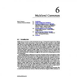
test regime is described in section III. Section IV includes the results of the tests simulated and Section V gives the conclusions. II. M ODELLING For this research, a typical HVDC VSC was considered. The VSC was simulated alone rather than with a second converter or a grid as this allows the issues associated with the faults to be isolated and analyzed. Many faults that could be tested, such as line to line faults, will likely result in full power loss. Two of the most likely faults that could permit partial power transfer capability were simulated: a DC line to ground fault and a single phase transformer fault. A. Converter Model The Multi-level Modular Converter (MMC) [8] shown in Fig. 1 is constructed with six arms, two for each AC phase, connected to the positive and negative DC rails. The arms consist of a series chain of capacitor cells, switched into or out of conduction by either a half-bridge or a full H-bridge of IGBT switches. The output voltage is constructed by switching the appropriate number of cells into conduction such that the arm voltage is equal to the difference between the DC rail voltage and the desired AC voltage. Converters based on full-bridge and half-bridge capacitor cells were simulated in order to compare their capabilities. The simulation models were component-level, meaning that individual IGBTs and their switching were represented. The nominal voltage of each module was 1.5 kV and 14 modules
were used in each arm. The converter was rated at 20 kV DC and 1 kA DC and the converter side AC voltage was set to have a peak of 10 kV (so no over-modulation was required). The converter was simulated at a significantly lower power rating than will be utilized in a supergrid to keep the number of modules small and allow a reasonable simulation time. At the DC rails of the converter a small impedance was inserted to give a basic representation of a DC source that is not completely ‘stiff’. The converter current is controlled using proportional plus resonant controllers on each phase. The converter current references are pre-calculated rather than calculated using feedback for this set of simulations. During conduction the cell capacitors charge/discharge depending on the current direction and switching pattern, a DC current is circulated in each arm to ensure the cells remain at the correct voltage. This DC current can provide most of the cell balancing but cannot account for energy differences between the top and bottom arms in any given phase or between the cells in any given arm. Following the work of [9], an AC current is circulated such that the arms can transfer energy between them to balance their cells. To ensure the cells remain evenly charged within an arm a cell rotation calculation is used so that they receive approximately equal duty. B. System The system simulated (shown in Fig. 2) consists of the converter, an AC grid, a transformer and a pair of DC sources. The grid is simply three single-phase AC voltage sources at 11kV connected to a star point which is grounded. This represents a strong AC grid like that found at the onshore converter in an HVDC link. The transformer is simulated as three single-phase transformers in a delta-star configuration. The midpoint of the star is made available to the converter for certain fault cases. The DC side of the converter is supplied by two strong DC sources representing a DC grid or a well controlled HVDC link. C. Faults As this research was to determine the power transfer capability of the MMC following partial faults, no actual fault resistances or device failures were simulated. The faults do not automatically clear as it is important to test that the converters are able to transfer the power for a significant period of time. Faults such as those tested are liable to require a long period of time to repair due to the difficulties in accessing offshore
converters, this will be in the order of months or weeks rather than days or hours. The DC line to ground fault was simulated by setting one of the DC voltage sources to zero whilst the other remains at 10 kV. This can either represent a fault on a grid where the other converters control the voltage down to 10 kV rather than allowing the remaining line to double its voltage. Alternatively this could be seen as the remaining 10 kV source acting as a surge arrester and thus not allowing the voltage to rise above 10 kV. The limit to power output is expected to be 10 MW for a 20 MW converter as this will keep the DC current at its rated value. The return of the current could be through ground for a short period of time, or a low voltage metallic return. As the converter has its DC rails connected to 0 V and 10 kV there will be a 5 kV DC strain on the transformer windings. The transformer would need insulation sufficient to block this. The transformer fault was simulated by switching out one of the three transformers using the switches shown in Fig. 3. The converter arms on the faulted phase are then connected to the neutral. For these simulations the transformer is only removed on the secondary side, in practice it could and would be removed from the primary circuit without affecting the results. The removal of one of the transformers means that the secondary voltages and currents are significantly different from those proceeding the fault. The voltages remain the same magnitude but the voltage on the faulted phase (phase C in these simulations) is now zero on the secondary (converter) side. The currents, driven from the converter need to be adjusted so that they remain at their prefault levels on the primary (grid) side.
iA = ia − ib iB = ib iC = −ia
√
π ) 6 √ 2π π = 3Iˆb sin(ωt − + ) 3 6 √ 2π π ˆ = 3Ic sin(ωt + + ) 3 6 =
3Iˆa sin(ωt +
a
ia
iA
B
b
ib iB
A
iC
C
c
ic
n Fig. 3.
Disconnection of a transformer during a transformer fault Primary (Grid) 120
90
150
Pre-Fault
60 0.5
1 30
180
0
210
330 240
120
270
90
150
Post-Fault
Secondary (Converter)
60
180
0
210
330 270
300
60 0.5
180
1 30 0
210
330 240
1 30
90
150
300
0.5
240
120
120
270
90
150
300
60 0.5
180
1 30 0
210
330 240
270
300
Fig. 4. Current phasors for primary and secondary of the transformer, preand post-fault. Plots in per-unit with the base being converter current rating. Plots show resulting currents if 1pu current was transferred pre-fault.
(1) (2) (3)
Equations (1) to (3) show the new relationship between primary and secondary currents of the faulted transformer. They show that the three primary currents are produced using √ two secondary side currents. These currents must each be 3 larger in magnitude than the unfaulted case as this magnitude increase is a property of the delta star relationship which no longer holds. Additionally they must be phase shifted such that their difference makes the third desired primary current. Fig. 4 shows the phasors of the primary and secondary currents, before and after the transformer is switched out. As the currents no longer sum to zero at the DC rails of the converter, a large 50 Hz current ripple will be seen at the terminals. The third phase is used to circulate a compensating current. This compensating current is larger than the other two phase currents and limits the maximum power transfer. As with the DC line to ground fault this is expected to be 10 MW in the 20 MW system.
III. T EST S PECIFICATION For each test the converter was commanded to produce 10 MW throughout. This means that, if predictions were correct, the AC side currents and voltages remain undisturbed through the fault. After an initial PLL settling period of approximately 0.1 s the fault is applied at 0.3 s and the test was run for 0.8 s to show that the end result is stable. The full set of AC and DC voltages and currents were monitored along with the average cell voltage for each arm (cell rotation ensures all cells are within a small amount of this average), and the full set of six arm currents. The two output plots are separated into System and Converter plots. The system plots (figures 5, 6 and 8) show the voltages and currents of both the AC and DC sources. The converter plots (figures 7 and 9) show the voltages produced by the converter, the arm currents and cell voltage averages for the six arms in the converter. IV. R ESULTS A. Line to Ground DC Fault When using half-bridge cells the system is unable to function during DC faults. If the DC voltage is below the peak AC
10 Vgrid (kV)
Vgrid (kV)
10 0 −10
0
0.1
0.2
0.3
0.4
0.5
0.6
0.7
0 −10
0.8
0 −10
0
0.1
0.2
0.3
0.4
0.5
0.6
0.7
VDC (kV)
VDC (kV)
0.3
0.4
0.5
0.6
0.7
0.8
0
0.1
0.2
0.3
0.4
0.5
0.6
0.7
0.8
0
0.1
0.2
0.3
0.4
0.5
0.6
0.7
0
0.1
0.2
0.3
0.4
0.5
0.6
0.7
0.8
0
0.1
0.2
0.3
0.4 Time(s)
0.5
0.6
0.7
0.8
0 −20
0.8
2 IDC (kA)
10 0
0.2
0.3
0.4 Time(s)
0.5
0.6
0.7
Fig. 5. System voltages and currents for the half-bridge MMC line to ground fault
voltage then the IGBT diodes start conducting and the current becomes uncontrolled, a phase reactor of 0.1pu prevents this from rising above 10pu current. This could potentially damage the converter. Fig. 5 shows this is the case when applying a line to ground fault with the half-bridge version of the MMC. No power is able to be transferred in this case and the converter would have to be tripped at the AC breakers (or a DC circuit breaker if fitted). The full bridge converter is able to reverse the cell voltages to oppose the AC peak voltage when needed (at the expense of higher losses and more devices). This means that the converter is able to ride through a DC line to ground fault without significant disturbance on the AC side. From the system plots (Fig. 6) it can be seen that the DC current rises to rated as the DC voltage falls. Due to the earthing arrangements the converter is able to float to keep the voltage balanced across the arms. On the converter side (Figure. 7) it is clear that nothing is disturbed during the fault and the new operating point is stable and the converter could run with one DC line and 10 MW power transfer indefinitely. B. Transformer Fault With the transformer fault, the performance of the two cell types was near identical so only the full bridge results are presented here for brevity. From the system plots (Fig. 8), it is clear that the AC grid voltage, and current, are unaffected by the removal of the transformer, this shows that the response to the fault is appropriate. However, some additional ripple has been applied to the DC voltage as the power draw from the DC side is no longer constant. Within the converter (Fig. 9), the two unfaulted phases see higher currents and larger cell voltage variation. This is due to the requirement to transfer
0 −2
0.8
Fig. 6. System voltages and currents for the full-bridge MMC line to ground fault
Vconverter (kV)
0.1
10 0 −10 0
0.1
0.2
0.3
0.4
0.5
0.6
0.7
0.8
0
0.1
0.2
0.3
0.4
0.5
0.6
0.7
0.8
0
0.1
0.2
0.3
0.4 Time(s)
0.5
0.6
0.7
0.8
1 Iarm (kA)
0
0 −1
2.5 Vcell (kV)
IDC (kA)
0.2
20
0
−10
0.1
0 −1
0.8
20
−20
0
1 Igrid (kA)
Igrid (kA)
10
2 1.5 1
Fig. 7. Cell voltages and arm currents for the full-bridge MMC line to ground fault
all of the remaining power through these phases. The third phase sees a yet higher current demand to balance out the DC ripple current. However, the new duty is causing the cells to drift from their nominal voltage. The DC ripple is kept to a minimum with this control but starts to increase as the cells drift from nominal. This simulation was a proof of concept style simulation therefore a full cell balancing arrangement was not in place to counter the variations seen in the third
Vgrid (kV)
10 0 −10
0
0.1
0.2
0.3
0.4
0.5
0.6
0.7
0.8
0
0.1
0.2
0.3
0.4
0.5
0.6
0.7
0.8
Igrid (kA)
1 0 −1
ability to transfer power under two subsystem faults. In both cases, a single line to ground DC fault and a single phase transformer fault, the converter is able to transfer 50% of the power indefinitely after the faults occur. This means that the loss of supply risk for this converter is lower than would otherwise be calculated if under the assumption that all power is lost in all cases. This in turn may allow for larger power ratings to be used when building HVDC links and HVDC grids. ACKNOWLEDGEMENTS
0
This work is supported by the Research Councils UK Energy Program Grand Challenge - Top and Tail Transformation Project. Grant Number EP/1031707/1
VDC (kV)
20
−20
0
0.1
0.2
0.3
0.4
0.5
0.6
0.7
0.8
2 IDC (kA)
R EFERENCES 0 −2
Vconverter (kV)
Fig. 8. fault
0
0.1
0.2
0.3
0.4 Time(s)
0.5
0.6
0.7
0.8
System voltages and currents for the full-bridge MMC transformer
10 0 −10 0
0.1
0.2
0.3
0.4
0.5
0.6
0.7
0.8
0
0.1
0.2
0.3
0.4
0.5
0.6
0.7
0.8
0
0.1
0.2
0.3
0.4 Time(s)
0.5
0.6
0.7
0.8
Iarm (kA)
1 0 −1
Vcell (kV)
3 2 1 0
Fig. 9. Cell voltages and arm currents for the full-bridge MMC transformer fault
phase. An alternative cell balancing technique will be required on the third arm when under this fault condition. The power of 10 MW was transferred to the AC side throughout the fault without AC side disturbance, as planned. V. C ONCLUSIONS Presented in this paper are some initial results on the practicality of connecting very large HVDC links to existing AC grids. A multi-level modular converter was tested for its
[1] SP Transmission, “Western HVDC Link Website,” http: //www.westernhvdclink.co.uk/. [2] National Grid, “National Grid Interconnectors - France,” http://www. nationalgrid.com/uk/Interconnectors/. [3] Y. Pipelzadeh, N. Chaudhuri, B. Chaudhuri, and T. Green, “System stability improvement through optimal control allocation in voltage source converter-based high-voltage direct current links,” Generation, Transmission Distribution, IET, vol. 6, no. 9, pp. 811 –821, september 2012. [4] D. Van Hertem, M. Ghandhari, and M. Delimar, “Technical limitations towards a supergrid 2014; a european prospective,” in Energy Conference and Exhibition (EnergyCon), 2010 IEEE International, dec. 2010, pp. 302 –309. [5] SQSS Review Group, “Largest Power Infeed Loss Amendment to GSR007 proposals,” www.nationalgrid.com/uk/Electricity/Codes/ gbsqsscode/reviews. [6] Siemens, “Trans Bay HVDC System,” http://www.energy.siemens.com/nl/ pool/hq/energy-topics/living-energy/issue-5/LivingEnergy 05 hvdc.pdf. [7] power-technology.com, “Alstom Grid secures utility contract from Svenska Kraftnt in Sweden,” http://www.power-technology.com/news/ newsalstom-grid-secures-utility-contract-from-svenska-kraftnt-in-sweden/. [8] A. Lesnicar and R. Marquardt, “An innovative modular multilevel converter topology suitable for a wide power range,” in Power Tech Conference Proceedings, 2003 IEEE Bologna, vol. 3, june 2003, p. 6 pp. Vol.3. [9] P. Munch, D. Gorges, M. Izak, and S. Liu, “Integrated current control, energy control and energy balancing of modular multilevel converters,” in IECON 2010 - 36th Annual Conference on IEEE Industrial Electronics Society, nov. 2010, pp. 150 –155.