Partitioning Digitally Programmable Power-Control for Applications to Ballasts Douglas C. Hopkins, Ph.D.
James Moronski
Energy Systems Institute 312 Bonner Hall, University at Buffalo Buffalo, New York 14260-1900
[email protected]
Binghamton University c/o 316 Rayelene Dr. Vestal, New York 13850
[email protected]
Abstract: The move to full digital control of power electronic circuits has been mixed. This paper describes the procession of technology to embed digital power control in power supply circuits, with particular attention to dimmable fluorescent lighting ballasts. Partitioning of power circuits shows a near optimum match with the evolving System on Chip (SoC) approach taken for microcontrollers to provide an integrated digital power control. A performance description of several approaches is given with performance bounds.
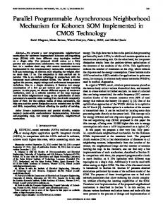
I. INTRODUCTION The move in the industry to fully digital control of power electronic circuits has been mixed. The use of microcomputers in lighting applications developed in the early 1980s as reputable energy savings data showed acceptable payback periods [1]. Typically, they were used for zoned control of lighting levels and scheduling, and EMI Filter
PFC
Housekeeping Power Supply
com m unications
PW M Tem perature sensing
ADC
OV, UV, Over Current
Inrush lim it, antiresonance
PW M
Output Filter
Figure 1 Power blocks and partitioning
they directly addressed ballasts as controllable power amplifier blocks [2] (side note: The system cost $1.02/sq.ft. with a two-year payback). Command sets were limited mostly to on/off and dimming.
0-7803-7404-5/02/$17.00 (c) 2002 IEEE
Microcomputer use was expanded in the mid 1990s from system level control to include supervision functions [3]. It was programmed to control subsystems and perform complete system self-test, including interrogation of the ballast, to ensure correct operation and to reduce maintenance costs. At the higher performance end, DSP control has been applied extensively in embedded motion control, and over the last three years, moved slowly into static, three-phase converters with some application to single phase. One application area of interest is power factor correction (PFC) circuits [4,5]. These algorithms are applicable to lighting ballasts as well as in motion control and active filtering. However, application to residential and commercial ballasts and systems does not appear practical due to cost and development complexity (relatively speaking). For low-end applications in dimmable lighting ballasts and power supplies, control is primarily accommodated by analog ASICs to attain low cost. These chips are usually dedicated to lamp types, configurations, communications and control interface. However, recently to broaden the market defined by a chip, hardware programmable power-control ASICs have been developed to lower system costs, yet retain high performance. There does not appear to be a generalized fully digital ballast approach for complete power circuit control readily available and proven in the marketplace. An intermediate approach between analog and all digital melds a digital communications interface to an analog ballast controller. A recent approach for dimmable fluorescent lighting ballasts by International Rectifier [6] uses a Microchip PIC16F628 for communications to a system controller (through a two wire protocol - DALI1). The PIC16F628 is a FLASHbased 8-bit CMOS Microcontroller. The microcontroller, then, outputs a PWM signal, which is filtered and sent to an IR 2159 hardware-programmable analog ballast-controller chip for dimming control. The ballast-controller chip has on chip highvoltage level translation for direct drive of the power inverter stage. The remainder of the power stage uses a PFC controller 1
DALI, Also known as: EN 60229, IEC 929, is an evolving IEC standard, IEC 60929, due for completion in September 2002. The protocol covers dimming of up to 64 addressable ballasts.
931 0-7803-7405-3/02/$17.00 (C) 2002 IEEE
chip, such as the L6561D from STMicroelectronics (per the IR app note). It is important to note the system partitioning dividing the low voltage control and the high voltage power drivers. IR technology has an advantage in the low versus high voltage partitioning. A fully digital approach is very timely to the industry and can bring some unexpected benefits, such as
•
The controller can be programmed in manufacturing for changes within a product family. Thus, reducing stocking fees.
• •
Digital can provide on-board diagnostics.
•
New opportunities in intellectual property are available, whereas "physical circuit configurations" now limit many manufacturers. Digital algorithms have replaced physical implementations of functions.
Ballasts can be field programmable, for retrofit updating.
In the examples given, there is sufficient computational power to run supervisory control of the ballast and communications at a networked systems level. However, there are several chips needed for control of the PFC, inverter and communications functions, where communications has a wide spectrum of needs depending on approach. The recent increase in processing speed and the use of embedded functions as found in the latest System on Chip (SoC) microcontrollers may provide the needed functional combinations to provide a complete, fully digital, fluorescent ballast controller. Though low to high voltage interface will need traditional approaches. A. Communications When ballast control is implemented in purely digital SoC, most protocols and hardware used to network these ballasts with a system (building) controller can be optimized in the SoC. Current protocols that include power line carrier, DALI, Lon Works, and simple analog voltage level representation have been developed around the idea that there is a communications controller located within the ballast, but not actually controlling the ballast operation of the PFC, inverter, etc. (Rightly so, since some of these protocols are licensed and are expensive to implement.) Since there is no "intimate" connection between communications hardware and power controller, much information about the current state of the power conversion hardware and load is not available. [10] With the integration of the communications controller with power control, operational parameters can be remotely and dynamically changed with immediate feedback. Also, new, cheaper and easier to implement protocols and algorithms can be developed that leverage the available hardware within the SoC. Libraries of
functions may evolve as now occurring with DSP applications. A robust communications protocol that has seen slow acceptance because of RX/TX chip costs is LonWorks by Echelon Corporation (circa 1990). The Echelon chip sets are the centerpiece to a lighting system and can provide power line carrier communications. There is a complete protocol for twoway communications. A ballast design is reported in [7] which uses the IR 2111 for inverter control, a Motorola MC34262 for the PFC control and the Echelon 3120 Neuron Chip for control. The 3120 Neuron Chip includes three CPUs, on-board nonvolatile and random-access memory, an applications I/O port, and a network communications port which implements Echelon’s LonTalk protocol. The communication stage is based on the power-line transceiver module PLT20 from Echelon. DALI, as mentioned earlier, is a communications protocol for dimming and on/off controls of electronic lighting ballasts. It is designed exclusively for lighting and is a development of the European companies Helvar, Huco, Philips, Osram, Tridonic, Trilux and Vossloh-Schwabe companies. A system using DALI would have up to 64 ballasts connected along a twisted-pair cable. Maximum network size is 300m, thus suitable for mid-size rooms and standalone systems. Sixty-four unique ballasts can be identified, and sixteen groups of ballasts. DALI messages consist of 1 start bit, 8 address bits, 8 databits, and 2 stopbits. A reply consists of 1 startbit, 8 databits, and 2 stopbits. Typical DALI network commands are "set light level", "go to minimum level", "turn lamp off", "set light at predefined level", "return light level", and "return status". Light levels are specified via a logarithmic regulation curve, running from 0.1% to 100%, specified in an 8 bit number. Operating parameters can be changed and stored dynamically in the ballast's memory, i.e. sixteen different light levels, fade time, fade rate, minimum light level, maximum light level, actual light level. Diagnostics include the status of each ballast and lamp. (See user group at DALI AG at http://www.dali-ag.org) To determine the feasibility of using a microcontroller, such as the Cypress PSoC series, requires a review of the partitioning of the power functions, and considerable re-thinking of control implementation and algorithm development to keep performance high and costs low. This paper describes power control partitioning for a generalized set of power topologies (resonant and bridge topologies), and a System on Chip (SOC) approach to lay the ground work for an integrated digital controller approach. II. POWER PARTITIONING A generic off-line power structure is composed of several power building blocks as shown in Fig. 1. In recent years several new topologies have been proposed that combine
932 0-7803-7405-3/02/$17.00 (C) 2002 IEEE
the PFC and inverter stages [8]. However, these do not lend themselves to dimming across a suitable range. The traditional parallel-loaded series resonant inverter remains the common topology in use. The categorization is consistent with the PEBB [9] approach. For lighting ballasts the specific blocks of interest are the PFC, inverter and communications. The blocks require both control and monitoring for operation and fault conditions. A minimum set of control and sensed parameters is given in Table 1.
applications in power control, particularly dimmable electronic ballasts. Now, previously code intensive activities can be "programmed" into embedded hardware offloading the microprocessor, and allowing more time for control, diagnostics and feature functions. Since the lighting ballast environment is relatively static, a SoC approach provides functional partitioning to allow the needed interface for a variety of communications standards used in external ballast control.
The control for the PFC and inverter are subdivided into circuit and system control requirements. The fault handling in the circuit control drives the requirements in performance and often limits a digital approach. Hence, clear definitions of the control functions are required to create the proper performance specification for a digital controller design. The present day operating parameters for dimmable fluorescent ballasts fall generally into the following values
TABLE 1. GENERIC POWER FUNCTIONS AND FEATURES
PFC:
• • •
PWM drive
• • •
ZVS super synchronous drive
Critically continuous operation
Switching frequency between 20kHz and 150kHz Inverter: 40kHz to 60kHz, Q