Citroën Berlingo van on a private driving circuit. ... A commercial vehicle - a
Citroën Berlingo van with .... 5 shows the decision diagram implemented in the.
Path following with backtracking based on fuzzy controllers for forward and reverse driving Joshu´e P´erez Rastelli, Jorge Godoy, Vicente Milan´es, Jorge Villagra, Enrique Onieva
To cite this version: Joshu´e P´erez Rastelli, Jorge Godoy, Vicente Milan´es, Jorge Villagra, Enrique Onieva. Path following with backtracking based on fuzzy controllers for forward and reverse driving. IV 2012 IEEE Intelligent Vehicles Symposium, Jun 2012, Alcala de Henares, Madrid, Spain. IEEE, 2012, .
HAL Id: hal-00732935 https://hal.inria.fr/hal-00732935 Submitted on 1 Oct 2012
HAL is a multi-disciplinary open access archive for the deposit and dissemination of scientific research documents, whether they are published or not. The documents may come from teaching and research institutions in France or abroad, or from public or private research centers.
L’archive ouverte pluridisciplinaire HAL, est destin´ee au d´epˆot et `a la diffusion de documents scientifiques de niveau recherche, publi´es ou non, ´emanant des ´etablissements d’enseignement et de recherche fran¸cais ou ´etrangers, des laboratoires publics ou priv´es.
2012 Intelligent Vehicles Symposium Alcalá de Henares, Spain, June 3-7, 2012
Path following with backtracking based on fuzzy controllers for forward and reverse driving J. Pérez, J. Godoy, V. Milanés, J. Villagrá, E. Onieva Abstract— Autonomous navigation is one of the most important challenges in the outdoor mobile robot field. For an automatic vehicle (which can be considered a type of outdoor mobile robot), path following can be implemented using global positioning systems (GPS) to allow the configuration of different navigation styles such as the shortest or fastest route, toll avoidance, etc., and even the definition of new routes. The main problem is when an unexpected circumstance occurs - traffic accident, road closure, etc. This paper presents an autonomous vehicle guidance system based on fuzzy logic systems to resolve unexpected road situations. A fuzzy steering controller performs the autonomous navigation, allowing reverse as well as forward driving in urban environments. Good performance was obtained in trials performed with a commercial electric Citroën Berlingo van on a private driving circuit.
I. I NTRODUCTION Path following, obstacle avoidance, and lateral control strategies have been extensively studied in the fields of mobile robots and intelligent transportation systems (ITS). In robotics, various navigation, obstacle avoidance, and localization algorithms have been developed for urban environments [1], [2]. The perspective taken in their research is that of unchanged environments, but in real vehicles driven on urban circuits, the environment can change for infrastructure work or emergency road closures. The presence of obstacles or road closures usually requires a new definition of the route or backtracking manoeuvres. Other groups have presented simulation results in dynamic environments, using techniques based on the Simultaneous Localization and Map Building (SLAM) to resolve problems with the location of the road in which a constrained Kalman filter algorithm is used to minimize errors in the vehicle’s location and the mapping [3]. Reverse driving is used in several real applications in the autonomous vehicle field. Most important ones have been tested with tractor-trailers [4], trucks [5] and parking manoeuvres, [6], [7]. Fuzzy logic techniques have been used to resolve the problem of automatically backing up a truck [5]. Although those experiments gave good results, they were performed only in simulations. Finally, the autonomous parking problem is partially resolved and implemented in high-end vehicles using the Park Mate system developed by Siemens. Other autonomous parking systems use ultrasonic sensor techniques Authors are with Programa AUTOPÍA at Centro de Automática y Robótica, Consejo Superior de Investigaciones Científicas, 28500 Madrid, Spain {joshue.perez, jorge.godoy, jorge.villagra, enrique.onieva}@csic.es. V. Milanés is a ME/Fulbright Visiting Scholar at California PATH, UC Berkeley. {
[email protected]}.
978-1-4673-2118-1/$31.00 ©2012 IEEE
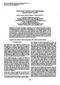
to parallel and reverse park in a space that is 1.5 times the vehicle’s length [6]. All these manoeuvres involve control of the steering wheel, throttle, and brake, but none considers a gearshift. Since fuzzy logic is a good intuitive technique for the control of nonlinear systems, the steering control of a vehicle is an excellent test-bench on which to test a controller of this kind. We here describe a novel architecture to perform forward and reverse driving using fuzzy logic. Also, the shortest alternative route to reach the destination is implemented should the first route be blocked. In section II, the instrumentation of the Citroën Berlingo van is explained. A description of the fuzzy controller is presented in Section III, detailing the forward and reverse controllers. Section IV describes the control scheme and the alternative path planning calculator. The experiments and results are presented in Section V, and some remarks and conclusions in Section VI. II. T ESTING P LATFORM A commercial vehicle - a Citroën Berlingo van with electric-powered motor - was instrumented to allow the automatic control of the vehicle’s actuators. A. Driving control The control of our autonomous vehicle can be divided into three main phases: perception, decision, and action. This architecture is capable of dealing with different vehicle models, actuators, and control methods [8]. An overview of the driving control can be seen in Fig. 1. The perception phase is responsible for receiving information from the environment. Different sensors can be used for this task: a Differential Global Positioning System (DGPS) as main sensor [9], an inertial measurement unit (IMU) [10], RFID sensors [11] and/or vision cameras [12]. Furthermore, data from other vehicles, monitoring stations, or traffic signals can be read onboard using a wireless network. The second phase, the decision phase, is responsible for evaluating the conditions obtained in the perception phase. It is subdivided in three sub-phases. The first one is the navigator that, in this case, will be defined as a set of GPS waypoints used as reference route. The second one is the adviser, whose mission is to select among all the different controllers. These controllers - all of them based on fuzzy logic - have been designed to take into account any traffic condition - straight-road tracking, bend tracking, overtaking or adaptive cruise control. Finally, the pilot made up by the low level controllers that receive which is the best controller
1108
Wifi Comunication
Action
Vision cameras
IMU
RFID
Onboard PC:
Decision
Perception
DGPS
- Decision Stage - Fuzzy control
Steering Wheel
Throttle
Brake
Gear Shift
Longitudinal Control
Lateral Control
Fig. 1.
Fig. 3.
Fuzzy control system of the steering wheel.
Van’s control architecture.
be selected from the onboard PC, bypassing the gearshift output (upper right part of Fig. 2), and connecting one of the analogue output of the digital-analogue module to set the reference voltage (0.9, 1.7, 2.5, and 3.3 volts, for P, R, N and D respectively). III. F UZZY C ONTROLLER
Fig. 2.
Electric van and the actuators.
for each traffic situation and generate the output for the actuators. The following sections will give details of the functionality of each of the system’s control modes. The first task is to determine the conditions of the environment, i.e., if the vehicle is advancing and the route is clear then it will continue on the route ahead, but if the route is blocked, the vehicle should stop and turn back if necessary to seek some other possible route. There are four possibilities: start driving, stop, drive forward, and drive in reverse. The action phase is in charge of the execution of the targets coming from the planning stage [9], [8]. B. Vehicle automation The hardware modifications applied over the steering wheel, the gearshift, the throttle and the brake are presented in Fig. 2. An automatic steering wheel system was taken conditioned to keeping the original steering wheel system of our electric car [13]. The system is organized as a DC motor connected to the steering bar through two gears, one in the motor rotor and the other in the shaft (lower left part of Fig. 2). The throttle and brake are controlled by a digital-analogue module and a electro-hydraulic pump respectively, which receive the reference from the longitudinal fuzzy controller (upper left and lower right part of Fig. 2) [9], [14]. The gearshift has four possible states: parking or blocked (P), reverse (R), neutral (N) and drive (D). In commercial vehicles such as our Citroën Berlingo, the gearshift is used as a trimmer, sending a control voltage to the gearbox which indicates the gear to use. Thus, the shifter position can
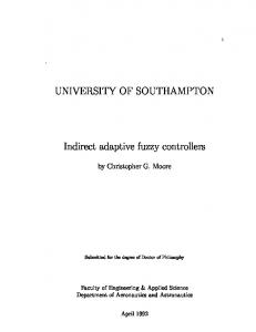
Fuzzy logic is a powerful Artificial Intelligence (AI) tool. Its use facilitates the control of processes so complex as those that are involved in autonomous vehicle driving In 1985, Sugeno demonstrated that a scale model car can be controlled by fuzzy logic using only human experience [15] as a knowledge base. In this line, the goal of the present work was to develop a fuzzy controller to perform autonomous guidance in reverse as well as forward driving, and to update the trajectory in the case that some unexpected driving circumstance is encountered along the route. The elements of a fuzzy system were defined by Zadeh [16], dividing it into three stages: fuzzification, inference, and defuzzification (Fig. 3). In the fuzzification stage, the actual "crisp" numerical values of the input variables are transformed into "linguistic" values that can be processed by the fuzzy processor. In the inference stage, the values of the output variables are generated in accordance with the knowledge base - human drivers’ experience. Finally, the defuzzification state yields the "crisp" values from the output fuzzy values. Methodologically, a fuzzy system contains input variables, a knowledge base comprising fuzzy rules, and output variables. Each input variable is defined through a set of linguistic values with their respective associated membership function. These input values are transformed and interpreted as fuzzy data in the inference stage. The knowledge base stores the rules as sentences in a natural-like language which is based on human experience. Finally, the linguistic values of the output variable are defined as Sugeno singletons, calculating their "crisp" values using the centre-of-mass method [17]. Our fuzzy controller is an experimental fuzzy coprocessor denominated ORBEX [18]. It allows variables to be defined and combined in rules of the form: IF... THEN.... Examples of this syntax will be presented later. The control of an autonomous vehicle can be divided into longitudinal (throttle, brake, and gear) and lateral (steering) control. Here, a fuzzy controller for the lateral control is presented together with action on the gear by the longitudinal
1109
functions. The small differences from the forward driving membership functions is that the reference point used to compute the lateral error has been moved to the rear-end of the car. With this simple inversion, the rule base for reverse driving is as follows: IF IF IF IF IF IF Fig. 4.
Membership functions of the lateral fuzzy control.
IV. C ONTROL
controller. Two main fuzzy controllers are used: one for forward driving (drive mode) and the other for reverse driving (reverse mode). Two control variables are considered in the lateral control loop: angular error and lateral error (Fig. ??). These variables are used to control the steering wheel position. The angular error is defined as the angle between the vehicle’s axis and the pre-defined route, in degrees. The lateral error is defined as the distance from the front of the vehicle to the pre-defined route, in metres. A. Forward driving fuzzy controller The lateral controller was a further development of that used in previous work [13]. The left-hand side of Fig. 4 shows the input variable membership functions used in the lateral control for the forward driving fuzzy controller. In each sampling period, the values of the two variables are determined from two consecutive GPS points. The membership functions have triangular and trapezoidal shapes. The rule base for the forward driving is the following: IF IF IF IF IF IF
Lateral Error Left THEN Steer. Wheel Pos. LEFT Lateral Error Middle THEN Steer. Wheel Pos. NOTHING Lateral Error Right THEN Steer. Wheel Pos. RIGHT Angular Error Left THEN Steer. Wheel Pos. LEFT Angular Error Middle THEN Steer. Wheel Pos. NOTHING Angular Error Right THEN Steer. Wheel Pos. RIGHT
Lateral Error Left THEN Steer. Wheel Pos. RIGHT Lateral Error Middle THEN Steer. Wheel Pos. NOTHING Lateral Error Right THEN Steer. Wheel Pos. LEFT Angular Error Left THEN Steer. Wheel Pos. RIGHT Angular Error Middle THEN Steer. Wheel Pos. NOTHING Angular Error Right THEN Steer. Wheel Pos. LEFT
The "Steer. Wheel Pos." is the output value whose linguistic values are defined as singletons as is suggested in [18]. The possible values are: RIGHT (1), NOTHING (0) and LEFT (-1). Where 1 means +540 degrees of the steering wheel to the right, al -1 is the opposite. The corresponding linguistic labels (for the membership functions) are: Right, Middle and Left. B. Reverse driving fuzzy controller Another fuzzy controller was designed to perform the autonomous reverse driving. Since emulating human behaviour is one of the goals of this work, the idea was to extrapolate the thinking of a human when driving backwards. So, analogously to the definition of the first controller, the rules were simply inverted because a human driver perceives the route as simply running backwards in time. The righthand side of Fig. 4 shows the reverse driving membership
SCHEME
After having defined the fuzzy controllers for the two driving control modes, forward and reverse, it was necessary to fix a decision algorithm to determine which of them to use. Autopia’s control architecture [8] permits the straightforward incorporation of driving controllers for different traffic circumstances. For instance, overtaking [19] ACC [9], and intersection manoeuvres [14] have already been included. In order to include the new reverse driving mode controller, two other driving situations were considered: the initial and stop sub-modes. The first situation corresponds to when the vehicle starts, and lasts until it has aligned itself to the initial path. The second situation is when the vehicle must stop either because it has arrived at its destination or for some other special situation such as a blocked path. Fig. 5 shows the decision diagram implemented in the vehicle. Initially, the destination is set. Then, the first path leading to this destination goal is selected, and the forward driving mode is enabled. From this moment onwards, the control architecture checks if there is any other vehicle on our route, and selects the appropriate controller -ACC, overtaking, intersections - accordingly. While no other vehicles are being encountered, the car proceeds until the end. In the case that some block in the defined route is detected, the vehicle stops, and a new path is sought. If this new route requires backtracking and no U-turn is possible, the reverse driving controller is selected and the car backs up until reaching a point at which it can turn around. Then, the forward driving controller takes over again, and it proceeds along the new path. There are some commercial algorithms (in navigators) to determinate a new alternative route. A road network is represented as a graph in which the streets are arcs labelled with their lengths to allow the computation of optimal routes, and the ends of streets, crossroads, and roundabouts are nodes. Each node stores data about the arcs and nodes connected to it. A route is represented as a node list. When a street is closed, the cartography system assigns infinity to its length to prevent its selection. Once the vehicle has detected an unavoidable obstacle (through cameras or RFID [12], [11]) the reverse gear is applied, and the cartography system seeks a point at which to perform a change of direction manoeuvre. Then a new route is computed, and the car continues driving normally.
1110
Cooperative Manoeuvres: • ACC. • Overtaking. • Access in the intersection. ...
Set the goal Define the path
Driving Forward
Yes
no
Is there another vehicle on the road ?
Yes
End of the Path? no
no
Continue to the goal
Is there a block signal ?
Yes
Stop the Vehicle
Stop the Vehicle Looking for a new path
Yes
Can it turn ? no
Yes
Reverse Driving
Fig. 5.
no
Is necesary reverse ?
Fig. 6. Vehicle’s trajectory in the fordward driving reverse driving control modes.
Control Scheme.
Straight-road Bends Total
V. E XPERIMENTS The experiments were conducted in a private driving circuit at the IAI-CSIC facilities. In order to test the behaviour of the designed system, two different trials have been done. First, the forward driving controller as well as the reverse one was tested independently but doing the same route. Second, a real traffic situation -road blocked- was tested. In this trial, both controllers were to cooperate to carry out this manoeuvre. Three reference speeds were set for these experiments: the starting speed (initial driving) was set at 6 km/h; the forward driving speed at 12 km/h; and the reverse driving speed at 7 km/h. For the first experiments, a route was selected within the circuit that included cornering to both the right and the left. In particular, the route included 8 curves, half to the left and half to the right. The results are shown in Fig. 6. The upper part plots the behaviour of the vehicle while doing the route in forward driving, showing the actual performance when following the pre-defined path. The speed used was the set 12 km/h, constant over the entire route because the purpose of the work was to test the lateral control. The lower part of the figure shows the performance of the vehicle when driving in reverse at the set target speed of 7 km/h. Both autonomous driving controllers gave excellent guidance results, simply with the inversion of the rule base in the fuzzy controller. In order to evaluate the algorithm we have compared the actual trajectory with the target one. The reference line is generated as a set of straight segments connected with
Forward driving 0.3182 0.8287 0.4997
Reverse driving 0.3148 0.9363 0.5222
TABLE I RMSE IN THE FIRST EXPERIMENTS WITH RESPECT TO REFERENCE LINE
quadratic Beziers curves [20]. Table I presents the root mean square error (RMSE) with respect to the reference line. It shows the RMSE for the whole route and also for the straight stretches and bends. As we can see the major error is when the vehicle takes corners. However, this error is lower than 1 metre in all the cases. Considering the dimensions of the vehicle and the road width this error is acceptable. We can also see that the error while driving in reverse is similar to the one while driving forward , because the vehicle dynamic infuluence is negligible at low speed. The second experiment was designed to test the vehicle’s ability to drive both forwards and backwards in a real environment. It consisted of initiating a route, encountering an obstacle, and reversing until a detour is found that permits the car to perform a change of direction manoeuvre so that it can continue driving to its final destination. To this end, we defined a destination (end point) and a route, as shown in the upper left illustration of Fig. 7 with the points (black dots) and routes (gray lines) that were used, together with the start and end points. During the experiment, when the car was approaching the point where the block was assumed to be, a signal was sent to the vehicle’s control
1111
Fig. 7.
Route using both controller modes and the definer of alternative route.
warning it of the block. This was a simulated signal since detecting obstacles was beyond the scope of the present work. The upper right part of Fig. 7 shows the selected path (grey) and the path actually covered (black) until the blocked path signal was received. The vehicle then entered in stop mode, and evaluated other possible routes. Once a new route was found, the control algorithm evaluated whether reverse driving was necessary. Since it found this to be so in the present case, the vehicle drove backwards until it could change direction. The bottom left part of Fig. 7 shows the route covered in reverse driving. The digital cartography allowed a short stretch of path to be found that was perpendicular to the road, and which the vehicle could enter to change direction. When the vehicle reached that point, it stopped, and then changed to forward driving mode and re-entered the road to follow the new path until the end point (bottom right part of Fig. 7). We have also made a similar error study for this case. Table II presents the RMSE in the last experiment with respect to the reference line, and now we distinguish among bends and straights both in forward and in reverse. The overall error is a little greater than in the first experiment, because of the U turn manoeuvre when the vehicle is to redefine its route (Lower right part of Fig. 6). The total RMSE is closer to the straight-road error, because the vehicle is considerably longer in forward driving than in reverse driving. Fig. 8 shows the vehicle’s speed (target and actual) over the entire length of this trial. At the beginning, the initial target speed was set (6 km/h), but the target very soon
Straight-road Bends Total
Forward driving 0.4219 0.9042 0.6283
Reverse driving 0.1868 0.5815 0.3947
Total of the tour 0.4086 0.8778 0.6123
TABLE II RMSE IN THE SECOND EXPERIMENT WITH RESPECT TO REFERENCE LINE
changed to 12 km/h once the vehicle was aligned with the path. When the vehicle detected the blocked path, the speed dropped until the vehicle had stopped. Then the reverse target speed was set (at between 92 and 105 seconds). Another stop (between 105 and 112 seconds) was required to change back to forward driving. When the vehicle started again, it was not aligned with the path, so the target speed was set to 6 km/h until alignment was achieved at around second 150. The target speed was then changed to 12 km/h until the end of the experiment. VI. C ONCLUSIONS We have presented the implementation of two fuzzy controllers for reverse as well as forward driving in autonomous vehicles. Using a commercial vehicle with instrumented actuators, manoeuvres with a high degree of complexity were performed. Fuzzy logic controls perform well in autonomous vehicle applications. In the present case, a simple change of the sense of the fuzzy controller rule base allowed the vehicle to be controlled in reverse driving. The fuzzy parameters can
1112
Fig. 8.
Actual longitudinal speed in the last experiment.
be designed and tuned against human driving experience. The controllers that were implemented gave good results on an urban-type circuit, both separately (first experiment) and conjointly in a complex manoeuvre (second experiment). The combination of steering wheel, throttle, and brake actuators has already yielded excellent results in the ITS field. With the inclusion of the gearshift as a new actuator, there should be further improvements in more precise and complex manoeuvres. The results suggest that an automatic controller for forward and reverse driving can be used in combination with a path following system to perform autonomous routes with real vehicles. This would thus offer a possible solution to make easier the driving task on roads as a complement to obstacle detection systems. ACKNOWLEDGMENT
[10] V. Milanés, J. E. Naranjo, C. Gonzélez, J. Alonso, and T. de Pedro, “Autonomous vehicle based in cooperative gps and inertial systems,” Robotica, vol. 26, no. 05, pp. 627–633, 2008. [11] J. Pérez, F. Seco, V. Milanés, A. Jiménez, J. Díaz, and T. de Pedro, “An rfid-based intelligent vehicle speed controller using active traffic signals,” Sensors, vol. 10, no. 6, pp. 5872–5887, 2010. [12] M. A. Sotelo, D. Fernandez, J. E. Naranjo, C. Gonzalez, R. Garcia, T. de Pedro, and J. Reviejo, “Vision-based adaptive cruise control for intelligent road vehicles,” in Proc. IEEE/RSJ Int. Conf. Intelligent Robots and Systems (IROS 2004), vol. 1, 2004, pp. 64–69. [13] J. Pérez, V. Milanés, and E. Onieva, “Cascade architecture for lateral control in autonomous vehicle,” Intelligent Transportation Systems, IEEE Transactions on, vol. 12, NO. 1, no. 6, pp. 73–82, 2011. [14] V. Milanes, J. Perez, E. Onieva, and C. Gonzalez, “Controller for urban intersections based on wireless communications and fuzzy logic,” IEEE Transactions on Intelligent Transportation Systems, vol. 11, no. 1, pp. 243–248, 2010. [15] M. Sugeno and M. Nishida, “Fuzzy control of model car,” Fuzzy Sets Syst., vol. 16, pp. 103–113, July 1985. [16] L. A. Zadeh, “Fuzzy sets,” Information and Control, vol. 8, pp. 338– 353, 1965. [17] A. V. Patel and B. M. Mohan, “Some numerical aspects of center of area defuzzification method,” Fuzzy Sets Syst., vol. 132, pp. 401–409, December 2002. [18] R. Garcia and T. D. Pedro, “First application of the orbex coprocessor: Control of unmanned vehicles,” Mathware and Soft Computing, vol. 7, pp. 265–273, 2000. [19] J. E. Naranjo, C. Gonzalez, R. Garcia, and T. de Pedro, “Lane-change fuzzy control in autonomous vehicles for the overtaking maneuver,” IEEE Transactions on Intelligent Transportation Systems, vol. 9, no. 3, pp. 438–450, 2008. [20] I. Skog and P. Handel, “In-car positioning and navigation technologies—a survey,” IEEE Transactions on Intelligent Transportation Systems, vol. 10, no. 1, pp. 4–21, 2009.
J. Godoy wants to specially thank to the JAE program (Consejo Superior de Investigaciones Científicas) and J. Pérez wants to thank to the FPI program for its support in the development of this work. V. Milanés wants to express his gratitute to the ME/Fulbright program. R EFERENCES [1] D. Bodhale, N. Afzulpurkar, and N. Thanh, “Path planning for a mobile robot in a dynamic environment,” in Robotics and Biomimetics, 2008. ROBIO 2008. IEEE International Conference on, feb. 2009, pp. 2115 –2120. [2] D. Fox, W. Burgard, F. Dellaert, and S. Thrun, “Monte carlo localization: Efficient position estimation for mobile robots,” in Proc. of the National Conference on Artificial Intelligence, 1999. [3] C. Menglong, Y. Lei, and C. Pingyuan, “Simultaneous localization and map building using constrained state estimate algorithm,” in Control Conference, 2008. CCC 2008. 27th Chinese, july 2008, pp. 315 –319. [4] C. Pradalier and K. Usher, “A simple and efficient control scheme to reverse a tractor-trailer system on a trajectory,” in Proc. IEEE Int Robotics and Automation Conf, 2007, pp. 2208–2214. [5] G. Chen and D. Zhang, “Back-driving a truck with suboptimal distance trajectories: a fuzzy logic control approach,” IEEE Transactions on Fuzzy Systems, vol. 5, no. 3, pp. 369–380, 1997. [6] T. hua Hsu, J.-F. Liu, P.-N. Yu, W.-S. Lee, and J.-S. Hsu, “Development of an automatic parking system for vehicle,” in Proc. IEEE Vehicle Power and Propulsion Conf. VPPC ’08, 2008, pp. 1–6. [7] T. X. P. Diem and M. Pasquier, “From operational to tactical driving: A hybrid learning approach for autonomous vehicles,” in Proc. 10th Int. Conf. Control, Automation, Robotics and Vision ICARCV 2008, 2008, pp. 285–290. [8] J. Perez, C. Gonzalez, V. Milanes, E. Onieva, J. Godoy, and T. de Pedro, “Modularity, adaptability and evolution in the autopia architecture for control of autonomous vehicles,” in Proc. IEEE Int. Conf. Mechatronics ICM 2009, 2009, pp. 1–5. [9] J. E. Naranjo, C. Gonzalez, R. Garcia, and T. de Pedro, “Cooperative throttle and brake fuzzy control for acc+stop&go maneuvers,” IEEE Transactions on Vehicular Technology, vol. 56, no. 4, pp. 1623–1630, 2007.
1113