302
IEEE TRANSACTIONS ON INDUSTRIAL INFORMATICS, VOL. 6, NO. 3, AUGUST 2010
PAUC: Power-Aware Utilization Control in Distributed Real-Time Systems Xiaorui Wang, Member, IEEE, Xing Fu, Xue Liu, and Zonghua Gu
Abstract—CPU utilization control has recently been demonstrated to be an effective way of meeting end-to-end deadlines for distributed real-time systems running in unpredictable environments. However, current research on utilization control focuses exclusively on task rate adaptation, which cannot effectively handle rate saturation and discrete task rates. Since the CPU utilization contributed by a real-time periodic task is determined by both its rate and execution time, CPU frequency scaling can be used to adapt task execution times for power-efficient utilization control. In this paper, we present PAUC, a two-layer coordinated CPU utilization control architecture. The primary control loop uses frequency scaling to locally control the CPU utilization of each processor, while the secondary control loop adopts rate adaptation to control the utilizations of all the processors at the cluster level on a finer timescale. Both the two control loops are designed and coordinated based on well-established control theory for theoretically guaranteed control accuracy and system stability. Empirical results on a physical testbed demonstrate that our control solution outperforms a state-of-the-art utilization control algorithm by having more accurate control and less power consumption. Extensive simulation results also show that our solution can significantly improve the feasibility of utilization control. Index Terms—Feedback control, power-aware computing, realtime embedded systems, utilization control.
I. INTRODUCTION
T
RADITIONAL approaches to handling end-to-end realtime tasks, such as end-to-end scheduling [33] and distributed priority ceiling [29], rely on schedulability analysis, which requires a priori knowledge of the tasks’ Worst-Case Execution Times (WCET). While such open-loop approaches work effectively in the closed execution environments of traditional real-time systems, they may violate the desired timing constraints or severely underutilize the system when task execution times are highly unpredictable. In recent years, a new Manuscript received October 01, 2009; revised March 24, 2010; accepted May 17, 2010. Date of publication June 14, 2010; date of current version August 06, 2010. This paper was presented in part at the Real-Time and Embedded Technology and Applications Symposium (RTAS), San Francisco, CA, 2009. This work was supported in part by the National Science Foundation (NSF) under CSR Grant CNS-0720663 and CSR Grant CNS-0915959 and in part by the NSF CAREER Award CNS-0845390, and in part by ONR under Grant N00014-09-1-0750. Paper no. TII-09-10-0249. X. Wang and X. Fu are with Department of Electrical Engineering and Computer Science, University of Tennessee, Knoxville, TN 37996 USA (e-mail:
[email protected];
[email protected]). X. Liu is with Department of Computer Science and Engineering, University of Nebraska, Lincoln, NE 68588 USA (e-mail:
[email protected]) . Z. Gu is with College of Computer Science, Zhejiang University, Hangzhou, China (e-mail:
[email protected]). Color versions of one or more of the figures in this paper are available online at http://ieeexplore.ieee.org. Digital Object Identifier 10.1109/TII.2010.2051232
category of real-time applications called Distributed Real-time Embedded (DRE) systems has been rapidly growing. DRE systems commonly execute in open and unpredictable environments in which workloads are unknown and may vary significantly at runtime. Such systems include data-driven systems whose execution is heavily influenced by volatile environments. For example, task execution times in vision-based feedback control systems depend on the content of live camera images of changing environments [18]. DRE systems call for a paradigm shift from classical real-time computing that relies on accurate characterization of workloads and platform. Recently, feedback control techniques have shown a lot of promise in providing real-time guarantees for DRE systems by adapting to workload variations based on dynamic feedback. In particular, feedback-based CPU utilization control [26], [37] has been demonstrated to be an effective way of meeting the end-to-end deadlines for soft DRE systems. The primary goal of utilization control is to enforce appropriate schedulable utilization bounds (e.g., the Liu and Layland bound for RMS) on all the processors in a DRE system, despite significant uncertainties in system workloads. In the meantime, it tries to maximize the system utility by controlling CPU utilizations to stay slightly below their schedulable bounds so that the processors can be utilized to the maximum degree. Utilization control can also enhance system survivability by providing overload protection against workload fluctuation [38]. However, previous research on CPU utilization control exclusively relies on task rate adaptation by assuming that task rates can be continuously tuned within specified ranges. While rate adaptation is an effective actuator for some DRE systems, it has several limitations. First, it is often infeasible to achieve desired utilization set points by rate adaptation alone [35]. For example, many DRE systems are configured based on tasks’ WCETs. Consequently, even when all the tasks are running at their highest rates, CPU utilizations are still way below the desired set points, resulting in severely underutilized systems and excessive power consumption. In that case, CPU frequency scaling can be used for power savings while keeping the utilizations slightly below the schedulable bounds. Second, many tasks in DRE systems only support a few discrete rates. While optimization strategies [12], [22] are developed to handle discrete task rates, they rely on the common assumption that task WCETs are known a priori and accurate, which makes them less applicable to DRE systems running in unpredictable environments. Third, the model of task rate in many applications could be complex and vary at runtime based on application evolution [15], [6]. As a result, the estimated task rate ranges are often inaccurate and may change significantly online, leading to unexpected rate saturation and even deadline misses when
1551-3203/$26.00 © 2010 IEEE Authorized licensed use limited to: UNIVERSITY OF TENNESSEE. Downloaded on August 17,2010 at 01:53:33 UTC from IEEE Xplore. Restrictions apply.
WANG et al.: PAUC: POWER-AWARE UTILIZATION CONTROL IN DISTRIBUTED REAL-TIME SYSTEMS
utilizations are higher than the schedulable bounds and can be lowered down only by rate adaptation. Finally, tasks in many real DRE systems may only have very narrow rate ranges or not allow rate adaptation at all, but the CPU utilizations of the processors still need to be controlled. Therefore, it is important to explore complementary ways for effective CPU utilization control. In this paper, we propose to use Dynamic Voltage and Frequency Scaling (DVFS) jointly with rate adaptation for utilization control. Since the CPU utilization contributed by a real-time periodic task is determined by both its rate and its execution time, CPU frequency scaling can be used to adapt task execution time for power-efficient utilization control. The integration of DVFS in utilization control introduces several new challenges. First, a centralized controller for simultaneous rate adaptation and DVFS would have a Multi-Input-Multi-Output (MIMO) nonlinear model. Therefore, multiple linear control loops are more preferable for acceptable runtime overhead. Second, different control loops need to be carefully designed to coordinate together for the desired control functions. Finally, the control accuracy and global system stability of the coordinated control solution must be analytically assured. This paper presents PAUC, a two-layer coordinated CPU utilization control architecture. The primary control loop uses DVFS to locally control the CPU utilization of each processor. In the meantime, the secondary control loop adopts rate adaptation to control the utilizations of all the processors at the cluster level on a finer timescale. Specifically, the contributions of this paper are fourfold: • We derive an analytical model that captures the system dynamics of the new CPU utilization control problem. • We design a two-layer coordinated control architecture and conduct detailed coordination analysis. • We implement our control architecture in an open-source real-time middleware system. • We present empirical results to demonstrate that our control solution outperforms a state-of-the-art utilization controller that relies solely on rate adaptation. Extensive simulation results also show that our solution can significantly improve the feasibility of utilization control. The rest of this paper is organized as follows. We formulate the new CPU utilization control problem in Section II. Section III presents the system model and control architecture. Section IV briefly introduces the rate adaptation loop, while Section V provides the detailed design and analysis of the CPU frequency scaling loop. Section VI discusses the coordination between different control loops. Section VII introduces the implementation of the control architecture in a real-time middleware system. Section VIII presents our empirical results on a physical testbed. Section IX reviews the related work. Finally, Section X summarizes this paper. II. PROBLEM FORMULATION In this section, we formulate the new CPU utilization control problem for DRE systems. A. Task Model We adopt an end-to-end task model [25] implemented by many DRE applications. A system is comprised of periodic
303
executing on processors tasks . Task is composed of a set of subtasks which may be located on different processors. A processor may host one or more subtasks of a task. The release of subtasks is subject to precedence constraints, i.e., subtask cannot be released for execution until its predecessor subtask is completed. All the subtasks of a task share the same rate. The rate of a task (and all its subtasks) can be adjusted by changing the rate of its first subtask. If a nongreedy synchronization protocol (e.g., release guard [33]) is used to enforce the precedence constraints, every subtask is released periodically without jitter. In our task model, each task has a soft end-to-end deadline related to its period. In an end-to-end scheduling approach [33], the deadline of an end-to-end task is divided into subdeadlines of its subtasks. Hence, the problem of meeting the end-to-end deadline can be transformed to the problem of meeting the subdeadline of each subtask. A well known approach for meeting the subdeadlines on a processor is to ensure its utilization remains below its schedulable utilization bound [25]. Our task model has three important properties. First, while has an estimated execution time available each subtask at design time, its actual execution time may be different from its estimation and vary at runtime due to two reasons: CPU frequency scaling or workload uncertainties. Modeling such uncertainties is important to DRE systems operating in unpredictable may be dynamienvironments. Second, the rate of a task cally adjusted within a range . This assumption is based on the fact that the task rates in many applications (e.g., digital control [28], sensor update, and multimedia [7]) can be dynamically adjusted without causing system failure. The rate ranges are determined by the applications (e.g., the limited sampling frequency of a sensor) and are not necessarily accurate. A task running at a higher rate contributes a higher value to the application at the cost of higher utilizations. Please note that our solution does not rely on continuous task rates. For a task with only discrete rates, its continuous rate value will be truncated to the highest discrete rate supported by the task that is below the continuous value. The utilization difference resulted from the truncation can be compensated by CPU frequency scaling. Third, the CPU frequency of each processor may be dynam. This assumption ically adjusted within a range is based on the fact that many today’s processors are DVFS-enabled. For processors that do not support DVFS, clock modulation can be used instead to change CPU frequency [23]. The frequency ranges are assumed to be continuous because a continuous value can be approximated by a series of discrete frequency levels supported by a processor, as we explain in Section VII. B. Problem Formulation Utilization control can be formulated as a dynamic constrained optimization problem. We first introduce some notation. , the control period, is selected so that multiple instances of each task may be released during a control period. is the CPU utilization of processor in the th control is not idle during time period, i.e., the fraction of time that . is the desired utilization set point interval is the invocation rate of task in the th on .
Authorized licensed use limited to: UNIVERSITY OF TENNESSEE. Downloaded on August 17,2010 at 01:53:33 UTC from IEEE Xplore. Restrictions apply.
304
IEEE TRANSACTIONS ON INDUSTRIAL INFORMATICS, VOL. 6, NO. 3, AUGUST 2010
control period. is the relative CPU frequency (i.e., CPU ) of processor frequency relative to the highest level in the th control period. Given a utilization set-point vector, , rate for each task , and frequency constraints for each processor , the control constraints ) is to dynamically choose goal at th sampling point (time task rates and CPU frequencies to minimize the difference between and for all the processors (1)
period can be modeled as , where is the estimated as defined in Section II-A. The estimated execution time of can be modeled as CPU utilization of processor (4) where is the set of subtasks located at processor . Example: Consider a system with two processors and three has only one subtask on processor . has two tasks. and on processors and , respectively. subtasks has one subtask allocated to processor . The estimated and are utilizations of
subject to constraints (2) (3) The rate constraints ensure that all tasks remain within their acceptable rate ranges. The frequency constraints ensure that all CPU frequencies remain within their acceptable ranges. The optimization formulation minimizes the difference between the utilization of each processor and its corresponding set point, by manipulating the rate of every task and the frequency of every processor within their constraints. The design goal is to ensure that all processors quickly converge to their utilization set points after a workload variation, whenever it is feasible under the constraints. Therefore, to guarantee end-to-end deadlines, a user only needs to specify the set point of each processor to be a value below its schedulable utilization bound. Utilization control algorithms can be used to meet all the end-to-end deadlines by enforcing the set points of all the processors in a DRE system, when feasible under the constraints. When a system’s workload exceeds the limit that can be handled within the rate and frequency constraints, utilization control needs to be combined with admission control in order to provide desired real-time guarantees. III. END-TO-END UTILIZATION CONTROL In this section, we model the end-to-end utilization control problem and present our control architecture. A. System Modeling Following a control-theoretic methodology, we establish a dynamic model that characterizes the relationship between the controlled variable and the manipulated variables and . We first model the utilization of one processor . As observed in previous research [4], [30], the execution times can be approximately estimated to be a linear of tasks on function of ’s relative CPU frequency.1 In many real-time systems, the CPU resource is the bottleneck of system performance and tasks are mostly computationally intensive. In those systems, the linear relationship can be a valid estimation. Therein the th control fore, the estimated execution time of task 1In general, the execution times of some tasks may include frequency-independent parts that do not scale linearly with CPU frequency [3]. We plan to model frequency-independent parts in our future work.
Note that the utilizations of and are coupled because , affects the utilizations of both the task rate of , i.e., and . We then define the estimated utilization change of , as (5) Note that is based on the estimated execution time . Since the actual execution times may be different from their estimation due to workload variations, we model the actual uti, as the following difference equation: lization of (6) represents the ratio between the where the utilization gain . For change to the actual utilization and its estimation example, means that the actual change to utilization is twice the estimated change. Note that the exact value of is unknown at design time due to the unpredictability of subtasks’ execution times. The system model (6) is nonlinear because the manipulated and , are in both the numerator and denomvariables, in (5), respectively. Thereinator of the definition of fore, we need to simplify the controller design for acceptable runtime overhead. There are two ways to simplify the system model. First, we may assume that all the processors always run at their highest CPU frequency and the utilizations are conbecomes 1 and trolled by rate adaptation only. As a result, the system model (6) becomes a linear model between and . Second, we can assume that the utilizations are controlled by frequency scaling only. As a reis a constant and the model becomes a linear model sult, and . between However, in a system that allows both rate adaptation and frequency scaling, relying solely on one adaptation strategy may unnecessarily reduce the system’s adaptation capability because both task rates and CPU frequencies can only be adapted within limited ranges. Therefore, a novel control architecture needs to be designed for utilizing both rate adaptation and frequency scaling to maximize the system’s adaptation capability.
Authorized licensed use limited to: UNIVERSITY OF TENNESSEE. Downloaded on August 17,2010 at 01:53:33 UTC from IEEE Xplore. Restrictions apply.
WANG et al.: PAUC: POWER-AWARE UTILIZATION CONTROL IN DISTRIBUTED REAL-TIME SYSTEMS
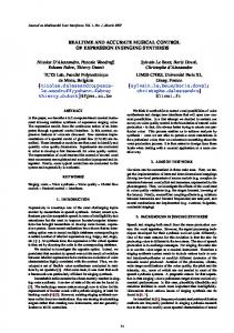
Fig. 1. The utilization control architecture of PAUC.
B. Control Architecture of PAUC In this paper, we propose PAUC, a two-layer utilization control architecture, as shown in Fig. 1. To avoid having a nonlinear model, our control architecture features two coordinated control loops running in different control periods. First, the cluster-level rate adaptation loop dynamically controls the utilizations of all the processors by adjusting task rates within their allowed ranges. Because the rate change of a task affects the utilizations of all the processors where the task has subtasks, this loop is a MIMO control loop, which works as folsends its lows: 1) the utilization monitor on each processor in the last control period to the Model Predicutilization for tive Controller; 2) the controller computes a new rate every task and sends the new rates to the rate modulators; and 3) the rate modulators change the task rates accordingly. Please note again that for a task with only discrete rates, the rate modulator will truncate its continuous rate value to the highest discrete rate supported by the task that is below the continuous value. Second, on every processor in the system, we have a local controller that controls the utilization by scaling the CPU frequency of the processor. The controller is a Single-Input-SingleOutput (SISO) controller because the CPU frequency change of only affects the utilization of . This loop works as follows: sends its utilization to 1) the utilization monitor on the local controller; 2) the controller computes a new CPU freand sends it to the frequency modulator on ; quency and 3) the frequency modulator changes the CPU frequency accordingly. Clearly, without effective coordination, the two control loops may conflict with each other because they are controlling the same variable, i.e., CPU utilization. To achieve the desired control function and system stability, one control loop, i.e., the primary loop, needs to be configured with a control period that is longer than the settling time of the other control loop, i.e., the secondary loop. As a result, the secondary loop can always enter its steady state within one control period of the primary control loop. The two control loops are thus decoupled and can be designed independently. The impact of the primary loop on the secondary loop can be modeled as variations in its system model, while the impact of the secondary loop on the primary loop can be treated as system noise. As long as the two control loops are stable individually, the whole system is stable.
305
In our design, we choose the task rate adaptation loop as the secondary control loop for two reasons. First, the secondary loop reacts faster to utilization variations. As a result, the secondary loop has the priority to increase the value of its manipulated variable(s) when the actual utilization is lower than the set point, especially at the beginning of a system run. We assume that a higher task rate contributes a higher system value to the application and system value is more important than power efficiency in our target real-time applications. Second, the secondary loop must remain stable despite its model variation caused by the primary loop. The stability of the rate adaptation loop is less sensitive based on our coordination analysis in (6). In PAUC, the rate adaptation loop tries to achieve the desired CPU utilization set points, while maximizing the task rates. When it is infeasible to control utilizations by rate adaptation alone (e.g., due to rate saturation or discrete task rates), the frequency scaling loop can help to achieve the desired set points on a coarser timescale, while reducing the power consumption of the processors. Since the core of each control loop is its controller, we introduce the design and analysis of the CPU frequency scaling controller in the next two sections, respectively. The implementation details of other components are provided in Section VII. IV. TASK RATE ADAPTATION LOOP In this section, we briefly introduce the system model and design of the rate adaptation loop. A. System Model Based on the control architecture, we assume that the relative CPU frequency for all the processors. The case when is analyzed in Section VI. Hence, the estimated utiin (5) becomes lization change (7) where . Based on (6), a DRE system with tasks and processors is described by the following MIMO dynamic model: (8) where
is a diagonal matrix, where and . is a vector including the estimated . utilization change (7) of each processor. is an matrix, where if one or more if subtasks of task are allocated to processor , and is allocated to processor . no subtask of task B. Controller Design In this paper, we adopt the EUCON algorithm presented in our previous work [26] for rate adaptation. EUCON features a Model Predictive Controller (MPC) that optimizes a cost function defined over control periods in the future, called the prediction horizon. The control objective is to select control incontrol periods, called control horizon, puts in the following
Authorized licensed use limited to: UNIVERSITY OF TENNESSEE. Downloaded on August 17,2010 at 01:53:33 UTC from IEEE Xplore. Restrictions apply.
306
IEEE TRANSACTIONS ON INDUSTRIAL INFORMATICS, VOL. 6, NO. 3, AUGUST 2010
that minimize the following cost function, while satisfying the constraints:
B. Controller Design The Z-transform of model (10) with
is (11)
and are the Z-transforms of and , respectively. Following standard control theory [13], the transfer function of the closed-loop system with the conis troller transfer function as where
(9) where is the prediction horizon, and is the control horizon. The first term in the cost function represents the tracking error, and a i.e., the difference between the utilization vector defined in [26]. By minimizing reference trajectory the tracking error, the closed-loop system will converge to the utilization set points if the system is stable. The second term in the cost function represents the control penalty. This control problem is subject to the rate constraints (2). The detailed design and analysis of EUCON are available in [26]. Although the rate adaptation loop has been proved to be stable in [26], in order for the coordinated control architecture to be stable, the stability and settling time of the rate adaptation loop need to be reexamined by considering the impact from the frequency scaling loop. The detailed coordination analysis is presented in Section VI. V. CPU FREQUENCY SCALING LOOP
(12) , we adopt the minimal proTo design the controller totype design method in [17], [27] to specify the desired behavior of the closed-loop system. Specifically, is prewithin one control period, i.e., ferred to converge to . In Z-transform, this requirement translates to the following transfer function for the closed-loop system controlled by the controller: (13) Hence, from (12) and (13), we get the designed Proportional (P) controller transfer function as (14)
In this section, we model, design, and analyze the CPU frequency scaling loop in PAUC. The time-domain form of the controller (14) is
A. System Model Based on our control architecture, the frequency scaling loop can be designed separately from rate adaptation. As a result, model (6) can be simplified by having in (5) as a constant . This decouples different processors because, as discussed in Section III-A, processors are coupled to each other due to the fact that the rate change of a task may affect the utilizations of all the processors where its subtasks are located. The utilization of each processor can now be modeled individually because the CPU frequency change only affects the execution times of all the subtasks on . is Specifically, the model of processor (10) The model cannot be directly used to design controller because the system gain is used to model the uncertainties in task execution times and thus unknown at design time. Therefore, we design the controller based on an approximate system . In a real system model, which is model (10) with where the task execution times are different than their estimations, the actual value of may become different than 1. As a result, the closed-loop system may behave differently. However, in Section V-C, we show that a system controlled by the can remain stable as long as controller designed with is within a certain range. This range is esthe variation of tablished using stability analysis of the closed-loop system by considering the model variations.
(15) We choose to use a P controller instead of a more sophisticated controller such as a PID (Proportional-Integral-Derivative) controller because the actuator already includes an integrator such that zero steady state error can be achieved without resorting to an I (Integral) part. The D (Derivative) part is not used because it may amplify the noise in utilization in unpredictable environments. It is easy to prove that the controlled system is stable and has . The detailed proofs can be zero steady state errors when found in a standard control textbook [13] and are skipped due to space limitations. The desired CPU frequency in the th control period is (16)
C. Control Analysis for Model Variation In this subsection, we analyze the system stability when the designed P controller is used on a system with . A fundamental benefit of the control-theoretic approach is that it gives us theoretical confidence for system stability, even when the task execution times are significantly different from their estimations.
Authorized licensed use limited to: UNIVERSITY OF TENNESSEE. Downloaded on August 17,2010 at 01:53:33 UTC from IEEE Xplore. Restrictions apply.
WANG et al.: PAUC: POWER-AWARE UTILIZATION CONTROL IN DISTRIBUTED REAL-TIME SYSTEMS
The closed-loop transfer function for the real system is
(17) The closed-loop system pole in (17) is . In order for the system to be stable, the pole must be within the unit circle. . The Hence, the system will remain stable as long as result means that the actual utilization change cannot be twice the estimated utilization change. To handle systems with an actual that is outside the established stability range, an online model estimator implemented in our previous work [39] can be adopted to dynamically correct the system model based on the real utilization measurements, such that the system stability can be guaranteed despite significant model variations. We now analyze the steady-state error of the controlled system when (18) Equation (18) means that we are guaranteed to achieve the desired CPU utilization as long as the system is stable. VI. COORDINATION ANALYSIS We now analyze the coordination needed for the frequency scaling and rate adaptation loops to work together with global stability. The analysis here, as well as the control architecture design in Section III and our empirical results, demonstrates the importance of coordinating different control loops, which is a major contribution of our paper. First, we need to ensure that the stability of the rate adaptation loop will not be affected when the frequency scaling loop . Given a specific changes the CPU frequency and so task set, the stability condition of the rate adaptation loop as a range of (i.e., the ratio between the actual utilization change and the estimated change) can be established by following the steps presented in [26]. For example, the stability condition of the task set used in our experiments is that the actual change cannot be 10 times the estimated change. Accordingly, we must guarantee that the relative CPU frequency of each processor , because the is not smaller than 0.1, i.e., rate adaptation controller is designed with the assumption of . This constraint must be enforced in the frequency scaling loop. One of the reasons for us to choose the rate adaptation loop as the secondary loop in our control architecture is that it has a larger stability range and thus is less sensitive to the impact of the primary loop. Second, we must guarantee that the frequency scaling loop is . Since the frequency scaling loop is also stable, i.e., the primary loop of our two-layer control architecture, the difference between the actual and estimated utilization changes is mainly caused by the differences between the actual and estimated execution times. Therefore, it is preferable to use pessimistic estimation on execution times such that the controlled system can be guaranteed to be stable and the system oscillation can also be reduced. Please note that using pessimistic estimated execution times does not result in underutilization of the CPU as in systems that rely on traditional open-loop scheduling. This is
307
because our control architecture dynamically adjusts CPU frequencies and tasks rates based on measured utilization rather than the estimated execution times. The downside of using more pessimistic estimation on execution times is that it leads to a smaller system gain, which may cause slower convergence to the set points. However, since it is more important to guarantee system stability in a DRE system, it is still preferable to overestimate task execution times. We now rigorously derive the relationship between the convergence (settling) time of the system and the value of . By transforming the closed-loop transfer function (17) to the time domain, the system variation model . As commonly debecomes converges fined in control theory, the system settles when into the 2% range around the desired set point . Hence, the required number of control periods, , for the system to settle can be calculated as: . Based on a required convergence time, we can derive a range of . As long as is within this range, the system is guaranteed to achieve the required settling time. Third, we need to analyze the settling time of the rate adaptation loop in order to determine the control period of the frequency scaling loop. Since settling time has not been analyzed in [26], we now outline the general process of analyzing the settling time of the rate adaptation loop when the actual utilization . change is different from the estimated change, i.e., 1) Given a specific task set, we derive the control inputs (i.e., desired task rate changes) that minimize the cost function . The (9) based on the nominal system model with represent the control decision based control inputs on the estimated system model (19) where , and are parameter matrices. The designed MPC controller is a dynamic controller. Therefore, the stability analysis needs to consider the composite system consisting of the dynamics of the original system and the controller. 2) We then derive the closed-loop model of the composite system by substituting the control inputs derived in Step 1 . The closedinto the actual system model (8) with loop composite system is
(20) where is the identity matrix. Note that the closed-loop system model is a function of . 3) We calculate the dominant pole (i.e., the pole with the largest magnitude) of the closed-loop system. According to control theory, the value of the dominant pole determines the system’s transient response such as settling time. Based on our analysis, the task set used in our experiments has a settling time of 5 control periods under rate adaptation. The detailed derivation is not included due to space limitations. The control period of the rate adaptation loop is selected to be
Authorized licensed use limited to: UNIVERSITY OF TENNESSEE. Downloaded on August 17,2010 at 01:53:33 UTC from IEEE Xplore. Restrictions apply.
308
IEEE TRANSACTIONS ON INDUSTRIAL INFORMATICS, VOL. 6, NO. 3, AUGUST 2010
2 s to include multiple instances of each task, resulting in a sets. Therefore, the control period of tling time of the frequency scaling loop is set to 20 seconds, which is much longer than the settling time of the rate adaptation loop. VII. SYSTEM IMPLEMENTATION In this section, we first introduce the physical testbed used in our experiments and the implementation details of the control components. We then introduce our simulation environment. A. Testbed Our testbed includes four Linux servers, called RTES1 to RTES4, to run the end-to-end real-time tasks and a desktop machine to run the MPC controller. The four servers are equipped with 2.4 GHz AMD Athlon 64 3800+ processors with 1 GB RAM and 512 KB L2 Cache. The controller machine is a Dell OptiPlex GX520 with 3.00 GHz Intel Pentium D Processor and 1 GB RAM. All the machines are connected by a 100 Mbps internal Ethernet switch. The four servers run openSUSE Linux 11 with kernel 2.6.25 while the controller machine runs Windows XP. We implement our PAUC control architecture in FC-ORB, an open-source real-time Object Request Broker (ORB) middleware system [34]. FC-ORB supports end-to-end real-time tasks based on the end-to-end scheduling framework [25]. FC-ORB implements the release guard protocol to enforce the precedence constraints among subtasks. Our experiments on the testbed run a medium-sized workload that comprises 12 end-to-end tasks (with a total of 25 subtasks). The subtasks on each processor are scheduled by the RMS al, gorithm [25]. Each task’s end-to-end deadline is is the number of subtasks in task and is the where current rate of . Each end-to-end deadline is evenly divided into subdeadlines for its subtasks. The resultant subdeadline of equals its period, . The utilization set each subtask point of every processor is set to its RMS schedulable utilization bound [25], i.e., , where is the number of subtasks on . All (sub)tasks meet their (sub)deadlines if the desired utilization on every processor is enforced. We now introduce the implementation details of each component in our two-layer control architecture. Please note that the processes running the control loops have the highest priority in the system so that the feedback control loops can be executed even in overload conditions. Utilization Monitor: The utilization monitor uses the /proc/ stat file in Linux to estimate the CPU utilization in each control period. The /proc/stat file records the number of jiffies (usually 10 ms in Linux) when the CPU is in user mode, user mode with low priority (nice), system mode, and when used by the idle task, since the system starts. At the end of each control period, the utilization monitor reads the counters, and estimates the CPU utilization as 1 minus the number of jiffies used by the idle task in the last control period and then divided by the total number of jiffies in the same period. MPC Controller: The controller is implemented as a singlethread process running separately on the controller machine. Each time its periodic timer fires, the controller sends utilization requests to all the four application servers. The incoming
replies are handled asynchronously so that the controller can avoid being blocked by an overloaded application server. After the controller collects the replies from all the servers, it executes the control algorithm introduced in [26] to calculate the new task rates. The controller then sends the tasks’ new rates to the rate modulators on the servers for enforcement. If a server does not reply in an entire control period, its utilization is treated as 100%, as the controller assumes this server is overloaded with its (sub)tasks and so cannot respond. The control period of the rate adaptation loop is 2 s. The execution time of the MPC control algorithm has been analyzed in our previous work [34] to be 5 ms on a 2 GHz Intel Pentium4 processor. Therefore, the overhead of the rate adaptation control loop is smaller than 5 ms in a control period of 2 s, i.e., 0.25% CPU time. Rate Modulator: A Rate Modulator is located on each processor. It receives the new rates from the controller and then resets the timer interval of the first subtask of each task whose invocation rate needs to be changed. The overhead of rate modulation has been analyzed in our previous work [38] to be about 600 microseconds on a 2 GHz Intel Pentium4 processor. Proportional Controller: The controller is implemented as a process running on each of the four servers. With a control period of 20 s, the controller periodically reads the CPU utilization of the server, executes the control algorithm presented in Section V-B to compute the desired CPU frequency, and sends the new frequency to the frequency modulator on the server. Frequency Modulator: We use AMD’s Cool’n’Quiet technology to enforce the new CPU frequency. AMD Athlon 64 3800+ microprocessor has five discrete CPU frequency levels. To change CPU frequency, one needs to install the cpufreq package and then use root privilege to write the new frequency level into the system file /sys/devices/system/cpu/cpu0/cpufreq/scaling setspeed. A routine periodically checks this file and resets the CPU frequency accordingly. The average overhead (i.e., transition latency) to change frequency in AMD Athlon processors is about 100 s according to the AMD white paper report. Recent studies [21] have also shown that the overhead of DVFS can be in nanoseconds in future microprocessors and is thus small enough to be used in real-time systems. Since the new CPU frequency level periodically received from the proportional controller could be any value that is not exactly one of the five supported frequency levels. Therefore, the modulator code must locally resolve the output value of the controller to a series of supported frequency levels to approximate the desired value. For example, to approximate 2.89 GHz during a control period, the modulator would output the sequence 2.67, 3, 3, 2.67, 3, 3, etc., on a smaller timescale. To do this, we implement a first-order delta-sigma modulator, which is commonly used in analog-to-digital signal conversion. The detailed algorithm of the first-order delta-sigma modulator can be found in [23]. Power Monitor: The power consumption of each server is measured with a WattsUp Pro power meter by plugging the server into the power meter, which is connected to a standard 120 V AC wall outlet. The WattsUp power meter has an accu% of the measured value. To access power data, the racy of data port of each power meter is connected to a serial port of the data collection machine. The power meter samples the power
Authorized licensed use limited to: UNIVERSITY OF TENNESSEE. Downloaded on August 17,2010 at 01:53:33 UTC from IEEE Xplore. Restrictions apply.
WANG et al.: PAUC: POWER-AWARE UTILIZATION CONTROL IN DISTRIBUTED REAL-TIME SYSTEMS
309
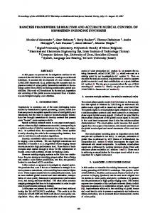
Fig. 2. CPU utilization control by frequency scaling under a workload increase from 600 to 1200 s. (a) CPU utilization, (b) CPU frequency and power consumption.
data every second and then sends the reading to the data collection program through a system file /dev/ttyUSB0. B. Simulation Environment To stress test PAUC in large-scale distributed real-time systems, we have developed an event-driven simulator implemented in C++. The simulator implements task scheduling in a distributed real-time system controlled by the rate adaptation loop and the CPU frequency scaling loop. Based on the frequency range of the real processors used in our testbed, the normalized range of processor CPU frequency in our simulations is configured as [0.417, 1] (to simulate AMD processors) or [0.75, 1] (to simulate Intel processors). The rate adaptation controller is implemented based on the lsqlin least squares solver in MATLAB. At the start time of the simulation, the simulator opens a MATLAB process to initialize the rate adaptation controller. At the end of each control period of the rate adaptation loop, the controller collects the CPU utilizations of the processors from their utilization monitors, and calls the least squares solver in MATLAB with the utilization vector as parameters. The solver then computes the desired rates for all the tasks and returns them to the rate modulators on the processors in the simulator to adjust the task rates. We adopt the power model proposed in [19] to estimate the power consumption of a processor based on its CPU frequency and CPU utilization. Specifically, the power model of the th processor is (21) can be determined by curve fitwhere model parameters ting based on the system identification experiments on a physical server. Based on the processors used in our testbed exper, iments, we have . The results in [19] report that power estimaand tion using this model is considerably accurate (confirmed by the %), with an average coefficient of determination %). The results on our testbed also error of 1% (worst case show that %. We assume that all the processors are homogeneous in our simulations, but it is easy to extend our power estimation to heterogeneous environments. We use randomly generated workloads in our simulations. The details of the workloads are presented in Section VIII-D. VIII. EXPERIMENTATION In this section, we first test the frequency scaling loop alone. We then show that the frequency scaling loop can effectively control utilizations when it is infeasible for a rate adaptation
controller to do so. We then demonstrate that the PAUC coordinated control solution can maximize the system’s adaptation capability for power-efficient utilization control. Finally, we present simulation results in large-scale systems with randomly generated workloads to show that our solution can significantly improve the feasibility of utilization control. A. Frequency Scaling Loop In this experiment, we disable the rate adaptation loop to evaluate the performance of the frequency scaling loop on server RTES1. As a common practice in real-time systems that rely on open-loop scheduling algorithms, the workload of RTES1 is configured with carefully tuned initial task rates such that the server has an initial CPU utilization of 0.72, which is its RMS bound. As shown in Fig. 2(a), at time 600 s, the execution times of all the tasks on RTES1 are suddenly increased by 8% to test the system’s capability of handling workload fluctuations. The increase makes the CPU utilization of RTES1 jump to 0.78, which is higher than the RMS bound and so may cause undesired deadline misses. Fig. 2(b) shows that the frequency scaling loop responds to the utilization increase by dynamically increasing the CPU frequency of the server processor from 2.0 to 2.18 GHz. As a result, the utilization returns back to the set point quickly. In contrast, An open-loop system without dynamic feedback would have its utilization stay above the RMS bound. At time 1200 s, the task execution times are suddenly reduced back to their original values, resulting in a utilization lower than the set point. The frequency scaling loop then responds by reducing the CPU frequency back to 2.0 GHz for power savings. To test the robustness of the controller, we conduct a set of experiments with different utilization set points. Fig. 3(a) plots the means and the standard deviations of RTES1’s CPU utilization after the controller enters the steady state. We can see that the frequency scaling loop can successfully achieve the desired utilization set points. Fig. 3(b) demonstrates that more power saving has been achieved when we allow the system to have a utilization set point closer to its RMS schedulable bound, i.e., 0.72. The maximum standard deviation for power is smaller than 1.5 W. B. Frequency Scaling Versus EUCON In this experiment, we show that frequency scaling can be used to control CPU utilizations when rate adaptation fails to do so in some cases. We compare the frequency scaling loop with a baseline, a state-of-the-art control algorithm called EUCON [26], which relies only on the rate adaptation loop introduced in Section III. Fig. 4(a) shows that EUCON fails to achieve
Authorized licensed use limited to: UNIVERSITY OF TENNESSEE. Downloaded on August 17,2010 at 01:53:33 UTC from IEEE Xplore. Restrictions apply.
310
IEEE TRANSACTIONS ON INDUSTRIAL INFORMATICS, VOL. 6, NO. 3, AUGUST 2010
Fig. 3. CPU utilization control by frequency scaling under different utilization set points. (a) CPU utilization. (b) Power consumption.
Fig. 4. Comparison of control accuracy between EUCON and the frequency scaling loop. (a) EUCON. (b) Frequency scaling activated from 400 s.
Fig. 5. Comparison of power consumption between EUCON and the frequency scaling loop. (a) EUCON. (b) Frequency scaling activated at 400 s.
the desired set points (0.74 for RTES2 and 0.72 for the other three servers) because the task rates saturate at the upper boundaries of their allowed ranges. As a result, the system is underutilized with unnecessarily high power consumption, as shown in Fig. 5(a). We then test the frequency scaling loop using the same workload with the rate adaptation loop disabled. In the experiment, to highlight the performance of the frequency scaling loop, we first let the system run in an open-loop manner (with no controller activated). Therefore, the system initially cannot achieve the desired CPU utilizations. At time 400 s, we activate the frequency scaling loop. Fig. 4(b) shows that the CPU utilizations quickly converge to their desired set points. As a result, all the servers achieve power savings [as shown in Fig. 5(b)], while still guaranteeing the end-to-end task schedulability. C. Coordinated Utilization Control Since both task rates and CPU frequencies can only be adapted within allowed ranges, the PAUC coordinated control
solution is designed to combine them based on control theory for maximized adaptation capability. In this experiment, we run the same workload with all the tasks starting with lower initial rates than those used in Section VIII-B. As a result, Fig. 6(a) shows that the utilizations controlled by the rate adaptation loop start from values lower than those in Fig. 4(a). Similar to Fig. 4(a), the rate adaptation loop fails to achieve the desired utilization set points (dashed lines in the figure) because tasks are already running at their highest possible rates allowed by their ranges. In this case, the CPU frequencies of the processors could be lowered for power savings. We then examine the frequency scaling loop alone by running the same experiment in Section VIII-B with lower initial task rates. Fig. 4(b) shows that the frequency scaling loop fails to achieve the desired utilizations this time because the tasks are running at lower rates. As a result, even when the processors are already running at their lowest CPU frequencies, utilizations still cannot converge to the desired set points. In this case, we
Authorized licensed use limited to: UNIVERSITY OF TENNESSEE. Downloaded on August 17,2010 at 01:53:33 UTC from IEEE Xplore. Restrictions apply.
WANG et al.: PAUC: POWER-AWARE UTILIZATION CONTROL IN DISTRIBUTED REAL-TIME SYSTEMS
311
Fig. 6. Infeasible utilization control by rate adaptation or frequency scaling individually. (a) Rate adaptation. (b) Frequency scaling activated at 400 s.
Fig. 7. CPU utilization control by the PAUC coordinated control solution (activated at 420 s). (a) CPU utilization. (b) Power consumption.
could allow tasks to run at higher rates to contribute a higher value to the system. We now evaluate the PAUC coordinated control solution. To highlight the performance of PAUC, we first run the rate adaptation loop, which achieves the highest rates for all the tasks, resulting in a high system value. At time 420 s, we activate the frequency scaling loop. Fig. 7(a) shows that the coordinated control solution successfully achieves the desired utilization set points. In the meantime, Fig. 7(b) demonstrates that servers RTES2, RTES3, RTES4 also receive considerable power savings. Therefore, the PAUC coordinated control solution can effectively control CPU utilizations to the desired set points, while achieving increased task rates and reduced power consumption. D. Simulation Results in Large-Scale Systems In this section, we conduct three sets of simulations to evaluate the effectiveness of PAUC in large-scale distributed realtime systems with randomly generated workloads. We compare PAUC with two baselines, EUCON and frequency-scaling-only, to examine the power consumption of the system and the percentage of randomly generated task sets that can be feasibly controlled to achieve the desired utilization set points under the three schemes. We define that a task set is feasible for utilization control if the utilizations of all the processors can be controlled to stay within 3% of their respective utilization set points in the steady state [35]. We randomly generate 1000 different synthetic task sets in the first set of simulations and 100 different task sets in the other two sets. The results in the first and the other two sets of simulations are the average results of the 1000 and the 100 task sets, respectively. In all the simulations, each task set
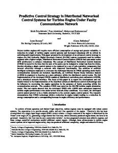
contains 20 periodic tasks and each periodic task has three subtasks that are allocated to three different processors. All the 60 subtasks are randomly deployed on 20 processors in all the simulations. The execution time of each subtask is randomly generated within the range of [23, 53] in each simulation run. In the first set of simulations, the task period range of each task is configured to be [200, 300] and the initial task rate of each task is set to 300. As shown in Fig. 8(a), PAUC outperforms both EUCON and frequency-scaling-only because it integrates rate adaptation and frequency scaling for maximized adaptation capability. EUCON has worse performance than frequency-scaling-only when the frequency range is from 0.417 to 1, because the normalized rate range size is relative small (i.e., ) compared to the normalized range size of exeand the normalized range cution time variations . As a result, the system size of CPU frequency under EUCON has only limited capability for rate adaptation. When the frequency range is reduced to [0.75, 1] (to simulate Intel processors), the performance of EUCON is impacted only slightly as it relies on rate adaptation. However, none of the task sets is feasible under frequency-scaling-only because now the is too normalized range size of CPU frequency small for utilization control. PAUC also has degraded performance as it relies on both rate adaptation and frequency scaling. Nonetheless, the percentage of feasible task sets under PAUC is still significantly higher than that under either EUCON or frequency-scaling-only. Fig. 8(b) shows the total power consumption of the 20 processors in the system averaged over the 1000 task sets. EUCON has the highest power consumption because it does not adjust CPU frequency for power savings.
Authorized licensed use limited to: UNIVERSITY OF TENNESSEE. Downloaded on August 17,2010 at 01:53:33 UTC from IEEE Xplore. Restrictions apply.
312
IEEE TRANSACTIONS ON INDUSTRIAL INFORMATICS, VOL. 6, NO. 3, AUGUST 2010
Fig. 8. Comparison of percentage of feasible tasks and power consumption under the three control schemes. (a) Percentage of feasible tasks. (b) Power consumption.
Fig. 9. Comparison of percentage of feasible tasks when task rate range varies. (a) CPU frequency range is from 0.417 to 1. (b) CPU frequency range is from 0.75 to 1.
Fig. 10. Comparison of power consumption when task rate range varies. (a) CPU frequency range is from 0.417 to 1. (b) CPU frequency range is from 0.75 to 1.
Frequency-scaling-only has the lowest power consumption because it relies only on frequency scaling for utilization control. PAUC has slightly higher power consumption than frequency-scaling-only but achieves a significantly higher feasibility percentage. This experiment demonstrates that PAUC improves the feasibility and power efficiency of utilization control. In the second set of simulations, since the task rate range is an important parameter, we change the rate range size of the tasks in the system to examine the performance of EUCON and PAUC. The highest allowed task rate of every task is fixed to be 300, while the lowest task rate is varied from 195 to 150 with a decrement of 5. As a result, the rate range size normalized to the range used before (i.e., [200, 300]) changes from 1.05 (i.e., ) to 1.5. As shown in Fig. 9(a), the percentage of feasible task sets controlled by EUCON increases almost linearly as the rate range size increases. The reason is that since the execution times are generated randomly, if the rate range size increases linearly, the probability of having feasible utilization control also increases approximately linearly. When we reduce the frequency range from [0.417, 1] to [0.75, 1] in Fig. 9(b), the percentage of feasible task sets under PAUC
drops to 86% when the normalized rate range is 1.05. This is because when both rate and frequency ranges are small, PAUC has a reduced adaptation capability. However, when either range has a reasonable size, PAUC can effectively utilize it to maximize the system adaptation capability. Fig. 10(a) and (b) show that the system power consumption under PAUC is lower than that under EUCON. When the frequency range is [0.417, 1], the power consumption under PAUC increases when the task rate range increases because PAUC tries to conduct rate adaptation first in order to achieve the highest task rates and so highest system value. With wider rate ranges, PAUC is able to control CPU utilizations without lowering the CPU frequencies of the processors, resulting in improved task rates. This experiment demonstrates that EUCON is sensitive to the range size of task rates, while PAUC can have an increased number of feasible task sets and reduced power consumption by integrating frequency scaling. In the third set of simulations, we examine EUCON and PAUC with hybrid workloads, where some tasks do not allow task rate adaptation (i.e., some tasks have constant invocation rates). The motivation is that hybrid workloads are more
Authorized licensed use limited to: UNIVERSITY OF TENNESSEE. Downloaded on August 17,2010 at 01:53:33 UTC from IEEE Xplore. Restrictions apply.
WANG et al.: PAUC: POWER-AWARE UTILIZATION CONTROL IN DISTRIBUTED REAL-TIME SYSTEMS
313
Fig. 11. Comparison of percentage of feasible tasks when the workload composition varies. (a) CPU frequency range is from 0.417 to 1. (b) CPU frequency range is from 0.75 to 1.
Fig. 12. Comparison of power consumption when the workload composition varies. (a) CPU frequency range is from 0.417 to 1. (b) CPU frequency range is from 0.75 to 1.
common in distributed real-time systems than ideal workloads where the rates of all the tasks are adjustable. To test the sensitivity of EUCON and PAUC, we vary the percentage of tasks with constant rates from 20% to 100%. As shown in Fig. 11(a) and (b), the number of feasible task sets under EUCON decreases significantly when the percentage of tasks with constant rates increases from 60% to 100%. This experiment demonstrates that EUCON has inferior performance with realistic workloads, where the majority of tasks do not allow rate adaptation. In contrast, PAUC can achieve a much greater adaptation capability by integrating rate adaptation and frequency scaling. Fig. 12(a) and (b) also demonstrate that PAUC is more power efficient. PAUC has reduced power consumption when the percentage of tasks with constant rates increases because PAUC relies more on frequency scaling for utilization control when more tasks do not allow their rates to be adjusted. IX. RELATED WORK A survey of feedback performance control in computing systems is presented in [1]. Many projects that applied control theory to real-time scheduling and applications are closely related to this paper. Steere et al. and Goel et al. developed feedback-based schedulers [32], [16] that guarantee desired progress rates for real-time applications. Abeni et al. presented control analysis of a reservation-based feedback scheduler [2]. Wang et al. proposed a two-layer response time control architecture for virtualized servers [40]. Lu et al. developed a middleware service that adopts feedback control scheduling algorithms to control CPU utilization and deadline miss ratio [38]. Feedback control has also been applied to power control [43], [23], [39] and digital control applications [8].
Various CPU utilization control algorithms (e.g., [38], [31], [24], [34]) have been recently proposed to guarantee real-time deadlines. For example, Lu et al. designed constrained MIMO utilization control algorithm for multiple processors that are coupled due to end-to-end tasks [26]. Wang et al. proposed decentralized utilization control algorithm for large-scale distributed real-time systems [37]. Yao et al. developed an adaptive utilization control algorithm [42]. However, all those algorithms assume that task rates can only be continuously tuned. Hybrid control theory [22] and optimization strategies [12] are adopted to handle discrete task rates based on the assumption that task WCETs are known a priori and accurate. In contrast to all the existing work that relies exclusively on rate adaptation, we present a two-layer control architecture that uses both rate adaptation and DVFS for power-efficient utilization control. Many energy-efficient real-time scheduling algorithms have been proposed (e.g., [3], [41], [10], [30], [4], and [43]). For example, Aydin et al. considered the energy-aware partitioning of real-time tasks for multiprocessor systems [5]. Huang et al. studied a similar problem in the context of heterogeneous multiprocessors [20]. Chen et al. extended the power models adopted in [5], [20] and proposed a real-time scheduling method that minimizes both dynamic and leakage energy consumption [9]. Aydin et al. addressed the frequency-independent parts in task execution times that do not scale linearly with CPU frequency [3]. Various thermal management algorithms have also been proposed for real-time systems (e.g., [11] and [14]). However, most existing work relies on detailed knowledge (e.g., WCETs) of workloads to minimize the energy consumption or system temperature, or maximize the system reward in an open-loop manner. While they can effectively guarantee task schedulability in closed environments without a feedback loop for adaptations, they may not be directly applied to DRE systems whose
Authorized licensed use limited to: UNIVERSITY OF TENNESSEE. Downloaded on August 17,2010 at 01:53:33 UTC from IEEE Xplore. Restrictions apply.
314
IEEE TRANSACTIONS ON INDUSTRIAL INFORMATICS, VOL. 6, NO. 3, AUGUST 2010
workloads may vary significantly at runtime. In contrast, we use DVFS as a knob to dynamically react to unpredictable workload variations instead of minimizing the energy consumption of the entire DRE system. X. CONCLUSION In this paper, we have formulated a new CPU utilization control problem based on both frequency scaling and rate adaptation. Since a centralized controller for simultaneous frequency scaling and rate adaptation would have a nonlinear system model, we designed PAUC, a two-layer coordinated CPU utilization control architecture. The primary control loop uses frequency scaling to locally control the CPU utilization of each processor, while the secondary control loop adopts rate adaptation to control the utilizations of all the processors in the system at the cluster level on a smaller timescale. Both the two control loops are designed and coordinated based on well-established control theory for theoretically guaranteed control accuracy and global system stability. Empirical results on a physical testbed demonstrate that our control solution outperforms EUCON, a state-of-the-art utilization control algorithm, by having increased adaptation capability and less power consumption. Extensive simulation results also show that our solution can significantly improve the feasibility of utilization control. REFERENCES [1] T. F. Abdelzaher, J. Stankovic, C. Lu, R. Zhang, and Y. Lu, “Feedback performance control in software services,” IEEE Control Systems, vol. 23, no. 3, pp. 74–90, 2003. [2] L. Abeni, L. Palopoli, G. Lipari, and J. Walpole, “Analysis of a reservation-based feedback scheduler,” in Proc. RTSS, 2002, pp. 71–80. [3] H. Aydin, V. Devadas, and D. Zhu, “System-level energy management for periodic real-time tasks,” in Proc. RTSS, 2006, pp. 313–322. [4] H. Aydin, P. Mejía-Alvarez, D. Mossé, and R. Melhem, “Dynamic and aggressive scheduling techniques for power-aware real-time systems,” in Proc. RTSS, 2001, pp. 95–105. [5] H. Aydin and Q. Yang, “Energy-aware partitioning for multiprocessor real-time systems,” in Proc. IPDPS, 2003. [6] S. A. Brandt and G. J. Nutt, “Flexible soft real-time processing in middleware,” in Proc. RTSS, 2004, pp. 77–118 [Online]. Available: http://www.springerlink.com/content/w0043qk112jgu251/ [7] G. C. Buttazzo, G. Lipari, M. Caccamo, and L. Abeni, “Elastic scheduling for flexible workload management,” IEEE Trans. Computers, vol. 51, no. 3, pp. 289–302, 2002. [8] A. Cervin, J. Eker, B. Bernhardsson, and K.-E. Arzen, “Feedback-feedforward scheduling of control tasks,” Real-Time Systems, vol. 23, no. 1, pp. 25–53, 2002. [9] J.-J. Chen, H.-R. Hsu, and T.-W. Kuo, “Leakage-aware energy-efficient scheduling of real-time tasks in multiprocessor systems,” in Proc. RTAS, 2006, pp. 408–417. [10] J.-J. Chen, C.-M. Hung, and T.-W. Kuo, “On the minimization of the instantaneous temperature for periodic real-time tasks,” in Proc. RTAS, 2007, pp. 236–248. [11] J.-J. Chen, S. Wang, and L. Thiele, “Proactive speed scheduling for frame-based real-time tasks under thermal constraints,” in Proc. RTAS, 2009, pp. 141–150. [12] Y. Chen, C. Lu, and X. Koutsoukos, “Optimal discrete rate adaptation for distributed real-time systems,” in Proc. RTSS, 2007, pp. 181–192. [13] G. F. Franklin, J. D. Powell, and M. Workman, Digital Control of Dynamic Systems, 3rd ed. Reading, MA: Addition-Wesley, 1997. [14] X. Fu, X. Wang, and E. Puster, “Dynamic thermal and timeliness guarantees for distributed real-time embedded systems,” in Proc. RTCSA, 2009, pp. 403–412. [15] S. Goddard and X. Liu, “A variable rate execution model,” in Proc. ECRTS, 2004, pp. 135–143.
[16] A. Goel, J. Walpole, and M. Shor, “Real-rate scheduling,” in Proc. RTAS, 2004, pp. 434–441. [17] G. C. Goodwin, S. F. Graebe, and M. E. Salgado, Control System Design. Englewood Cliffs, NJ: Prentice-Hall, 2000. [18] D. Henriksson and T. Olsson, “Maximizing the use of computational resources in multi-camera feedback control,” in Proc. RTAS, 2004, pp. 360–367. [19] T. Horvath and K. Skadron, “Multi-mode energy management for multi-tier server clusters,” in Proc. PACT, 2008, pp. 270–279. [20] T.-Y. Huang, Y.-C. Tsai, and E. T.-H. Chu, “A near-optimal solution for the heterogeneous multi-processor single-level voltage setup problem,” in Proc. IPDPS, 2007, pp. 1–10. [21] W. Kim, M. Gupta, G.-Y. Wei, and D. Brooks, “System level analysis of fast, per-core DVFS using on-chip switching regulators,” in Proc. 14th IEEE Int. Symp. High-Performance Computer Architecture (HPCA), 2008, pp. 123–134. [22] X. Koutsoukos, R. Tekumalla, B. Natarajan, and C. Lu, “Hybrid supervisory utilization control of real-time systems,” in Proc. RTAS, 2005, pp. 12–21. [23] C. Lefurgy, X. Wang, and M. Ware, “Power capping: A prelude to power shifting,” Cluster Computing, vol. 11, no. 2, pp. 183–195, 2008. [24] S. Lin and G. Manimaran, “Double-loop feedback-based scheduling approach for distributed real-time systems,” in Proc. HiPC, 2003, pp. 268–278. [25] J. W. S. Liu, Real-Time Systems. Englewood Cliffs, NJ: PrenticeHall, 2000. [26] C. Lu, X. Wang, and X. Koutsoukos, “Feedback utilization control in distributed real-time systems with end-to-end tasks,” IEEE Trans. Parallel Distrib. Syst., vol. 16, no. 6, pp. 550–561, Jun. 2005. [27] Y. Lu, T. F. Abdelzaher, and A. Saxena, “Design, implementation, and evaluation of differentiated caching services,” IEEE Trans. Parallel Distrib. Syst., vol. 15, no. 5, pp. 440–452, May 2004. [28] P. Marti, G. Fohler, P. Fuertes, and K. Ramamritham, “Improving quality-of-control using flexible timing constraints: Metric and scheduling,” in Proc. RTSS, 2002, pp. 91–100. [29] R. Rajkumar, L. Sha, and J. P. Lehoczky, “Real-time synchronization protocols for multiprocessors,” in Proc. RTAS, 1988, pp. 259–269. [30] S. Saewong and R. R. Rajkumar, “Practical voltage-scaling for fixedpriority RT-systems,” in Proc. RTAS, 2003, pp. 106–114. [31] J. A. Stankovic, T. He, T. Abdelzaher, M. Marley, G. Tao, S. Son, and C. Lu, “Feedback control scheduling in distributed real-time systems,” in Proc. RTSS, 2001, pp. 59–70. [32] D. C. Steere, A. Goel, J. Gruenberg, D. McNamee, C. Pu, and J. Walpole, “A feedback-driven proportion allocator for real-rate scheduling,” in Proc. OSDI, 1999, pp. –158. [33] J. Sun and J. Liu, “Synchronization protocols in distributed real-time systems,” in Proc. ICDCS, 1996, pp. 38–45. [34] X. Wang, Y. Chen, C. Lu, and X. Koutsoukos, “FC-ORB: A robust distributed real-time embedded middleware with end-to-end utilization control,” J. Syst. Softw., vol. 80, no. 7, pp. 938–950, 2007. [35] X. Wang, Y. Chen, C. Lu, and X. Koutsoukos, “On controllability and feasibility of utilization control in distributed real-time systems,” in Proc. ECRTS, 2007, pp. 103–112. [36] X. Wang, X. Fu, X. Liu, and Z. Gu, “Power-aware CPU utilization control for distributed real-time systems,” in Proc. RTAS, 2009, pp. 233–242. [37] X. Wang, D. Jia, C. Lu, and X. Koutsoukos, “DEUCON: Decentralized end-to-end utilization control for distributed real-time systems,” IEEE Trans. Parallel Distrib. Syst., vol. 18, no. 7, pp. 996–1009, Jul. 2007. [38] X. Wang, C. Lu, and C. Gill, “FCS/nORB: A feedback control realtime scheduling service for embedded ORB middleware,” Microprocess. Microsyst., vol. 32, no. 8, pp. 413–424, 2008. [39] Y. Wang, K. Ma, and X. Wang, “Temperature-constrained power control for chip multiprocessors with online model estimation,” in Proc. ISCA, 2009, pp. 314–324. [40] Y. Wang, X. Wang, M. Chen, and X. Zhu, “Power-efficient response time guarantees for virtualized enterprise servers,” in Proc. RTSS, 2008, pp. 303–312. [41] R. Xu, R. Melhem, and D. Mossé, “Energy-aware scheduling for streaming applications on chip multiprocessors,” in Proc. RTSS, 2007, pp. 25–38. [42] J. Yao, X. Liu, M. Yuan, and Z. Gu, “Online adaptive utilization control for real-time embedded multiprocessor systems,” in Proc. CODES ISSS, 2008, pp. 85–90. [43] Y. Zhu and F. Mueller, “Feedback EDF scheduling exploiting dynamic voltage scaling,” in Proc. RTAS, 2004, pp. 84–93.
+
Authorized licensed use limited to: UNIVERSITY OF TENNESSEE. Downloaded on August 17,2010 at 01:53:33 UTC from IEEE Xplore. Restrictions apply.
WANG et al.: PAUC: POWER-AWARE UTILIZATION CONTROL IN DISTRIBUTED REAL-TIME SYSTEMS
Xiaorui Wang (M’06) received the B.S. degree from Southeast University, China, in 1995, and the Ph.D. degree from Washington University, St. Louis, MO, in 2006, both in computer science. He is an Assistant Professor in the Department of Electrical Engineering and Computer Science at the University of Tennessee, Knoxville. He is an author or coauthor of more than 40 refereed publications. In 2005, he worked at the IBM Austin Research Laboratory, designing power control algorithms for high-performance computing servers. From 1998 to 2001, he was a Senior Software Engineer and then a Project Manager at Huawei Technologies Co. Ltd., China, developing distributed management systems for optical networks. His research interests include real-time embedded systems, power-aware computer systems, and cyber-physical systems. Prof. Wang is a member of the IEEE Computer Society. He is the recipient of the NSF CAREER Award in January 2009, the Chancellor’s Award for Professional Promise and the College of Engineering Research Fellow Award from the University of Tennessee in 2009 and 2010, respectively, the Power-Aware Computing Award from Microsoft Research in 2008, and the IBM Real-Time Innovation Award in 2007. He also received the Best Paper Award from the 29th IEEE Real-Time Systems Symposium (RTSS) in 2008.
315
Xue Liu is an Associate Professor in the Department of Computer Science and Engineering, University of Nebraska-Lincoln. Before that, he was an Assistant Professor in the School of Computer Science, McGill University, Canada from 2007 to 2009. He has worked briefly in the Hewlett-Packard Labs and IBM T. J. Watson Research Center. His research interests are in real-time and embedded systems, cyber-physical systems, networking, data centers, and software reliability. Prof. Liu received the IEEE TRANSACTIONS ON INDUSTRIAL INFORMATICS Best Paper Award in 2008.
Zonghua Gu received the Ph.D. degree in computer science and engineering from the University of Michigan, Ann Arbor, in 2004. He worked as a Postdoctoral Researcher at the University of Virginia from 2004 to 2005, and then as an Assistant Professor at the Hong Kong University of Science and Technology from 2005 to 2009 before joining Zhejiang University as an Associate Professor in 2009. His research area is real-time and embedded systems.
Xing Fu received the B.S. and M.S. degrees from Beijing University of Posts and Telecommunications, Beijing, China. He is currently working towards the Ph.D. degree in computer engineering at the Department of Electrical Engineering and Computer Science, University of Tennessee, Knoxville. His research interests are distributed real-time systems with power or thermal constraints and real-time middleware. His current research focuses on poweraware multicore real-time systems.
Authorized licensed use limited to: UNIVERSITY OF TENNESSEE. Downloaded on August 17,2010 at 01:53:33 UTC from IEEE Xplore. Restrictions apply.