PdP: Parallelizing Data Plane in Virtual Network Substrate Yong Liao ECE Department University of Massachusetts Amherst, MA 01003
[email protected]
Dong Yin
∗
Lixin Gao
Automation Department Northwestern Polytech Univ. Xi’an, ShanXi 710072, China
ECE Department University of Massachusetts Amherst, MA 01003
[email protected] [email protected]
ABSTRACT
1.
Network virtualization provides the ability to run multiple concurrent virtual networks over a shared substrate. However, it is challenging to design such a platform to host multiple heterogenous and often highly customized virtual networks. Not only minimal interference among different virtual networks is desired, high speed packet processing is also required. This paper presents PdP, a flexible virtual network platform which can achieve high speed packet processing. A PdP node has a cluster of machines that can perform packet processing in parallel. Each virtual network can be allocated with one or multiple forwarding machines so as to satisfy the packet processing requirement of the virtual network. Furthermore, a virtual network hosted in PdP has the freedom to be fully customized. Both the control plane and the data plane of a virtual network run in virtual machines so as to be isolated from other virtual networks. We have built a proofof-concept prototype of the PdP platform using off-the-shelf commodity hardware and open source software. The performance measurement shows promising results.
Network virtualization provides a powerful way to facilitate testing and deploying network innovations over a shared substrate. Currently the network research community is focusing on building a shared, wide-area experimental platform to support a broad range of research in networking and distributed systems. To that end, and more importantly, toward the long term goal of providing a global infrastructure in which multiple virtual networks, each customized to a specific purpose, could run concurrently, the virtual network substrate must have four key properties: (1) isolation between virtual networks to minimize the interference among them; (2) flexibility to customize the virtual networks to accommodate the various requirements of different virtual networks; (3) high-speed data plane packet processing performance to facilitate realistic experiments and attract long term applications; and (4) low cost in building that platform to lower the barrier of wide-area deployment. The challenge of building such a virtual network substrate is that the four properties, i.e., isolation, flexibility, high performance, and low cost, are often tightly coupled issues in system design so that usually we have to compromise one in order to improve another one. For example, special purpose hardware can achieve better packet processing performance but it can cost significantly more than commodity hardware. Another dilemma is that in order to achieve better performance, the data plane functions of a virtual network should have direct access to the hardware or run in the privileged domain of the hardware. However, opening low-level and close-to hardware programming interfaces usually results in poor isolation among virtual networks. A buggy function implemented in one virtual network can crash the whole system, e.g., shut down a machine hosting multiple virtual networks. Or a malicious user of the virtual network platform can easily affect other virtual networks residing at the same substrate. In order to prevent such a situation from happening but still offering the desired performance benefits, prior work proposes to design a set of well-tested building blocks which have direct access to the hardware or run in the privileged domain of the hardware [18,22]. Virtual networks can assemble those building blocks to implement their desired functions. However, that compromises the flexibility because the virtual networks are limited to the set of provided building blocks. This paper presents a virtual network platform called PdP. In designing PdP, we put flexibility as the first priority goal and try to provide each virtual network the freedom of fully customizing the control plane and the data plane (e.g., run-
Categories and Subject Descriptors C.2 [Computer-Communication Networks]: Network Architecture and Design—Network communications
General Terms Design, Experimentation, Performance
Keywords Network Virtualization, Virtual Network Platform, Parallelization ∗This work was performed when Dong Yin was a visiting student at University of Massachusetts.
Permission to make digital or hard copies of all or part of this work for personal or classroom use is granted without fee provided that copies are not made or distributed for profit or commercial advantage and that copies bear this notice and the full citation on the first page. To copy otherwise, to republish, to post on servers or to redistribute to lists, requires prior specific permission and/or a fee. VISA’09, August 17, 2009, Barcelona, Spain. Copyright 2009 ACM 978-1-60558-595-6/09/08 ...$10.00.
9
INTRODUCTION
ning something other than IP). The basic ideas behind the design of PdP are two-fold. First, both the control plane and data plane of a virtual network run in virtual machines to provide the isolation among virtual networks and the flexibility to customize each virtual network. Second, there are multiple physical machines serving as the “forwarding engines” in a PdP node. To achieve high speed packet processing, a virtual network can have multiple virtual machines (hosted in multiple forwarding engines) running in parallel to serve as its data plane. Note that we can combine PdP with virtual network platforms based on special purpose hardware, in which case PdP supports highly customized virtual network service; while the special hardware based data forwarding elements such as network processors support virtual network services that can be composed with the set of building blocks provided by the network processors. Therefore, PdP can complement the special purpose hardware based solutions. Although the basic idea behind PdP is promising, implementing this platform is challenging. First, for a PdP node, it is important to ensure that the packet processing performance scales with the number of forwarding engines. The machine which coordinates the forwarding engines should not become the bottleneck, especially when the coordination machine is implemented using commodity hardware. Second, parallel packet forwarding by multiple forwarding engines can lead to out-of-order packets and thereby resulting in degraded performance for the up-layer applications such as those applications using TCP. Therefore, it is important to reduce the amount of out-of-order packets. In summary, we make three main contributions in this paper. (I) To the best of our knowledge, PdP is the first virtual network platform which provides both high degree of customization and viable data processing performance. (II) PdP is the first platform demonstrating the scalability of parallelizing packet processing in one virtual network. (III) We have built a proof-of-concept PdP node prototype using off-the-shelf commodity hardware and open source software. Our experiments show promising results. The rest of this paper is organized as follows. Section 2 presents related work on virtual network platforms. Section 3 details the design of PdP. Section 4 presents the experiment evaluation results. Section 5 concludes this paper and projects our future work.
2.
plane, in which scenario its packet processing function has to run in OS user mode and essentially that virtual network loses the performance benefit provided by Trellis. The Virtual Router project [6] adopts the paravirtualization scheme provided by Xen [8] to virtualize a physical router box. A virtual router in VRouter can run in either privileged or unprivileged domains. Running a virtual router in unprivileged domain has unacceptable forwarding performance [16] but running it in privileged domain yields viable data plane performance [15]. However, letting a virtual network run directly in the privileged domain of the underlying hardware leads to less flexibility in customizing the virtual network, because a virtual network will be limited to use a set of “trustful” elements to avoid jeopardizing the shared substrate. The study in [14] explores another design option in which a virtual router can achieve close to native speed and can be highly customizable as well. The idea is to run virtual router in unprivileged domain for high degree of isolation and let each virtual interface exclusively use a physical NIC (this is called direct mapping) for better IO performance. But the number of virtual routers hosted in a machine would be limited by the available physical NICs. The Supercharging PlanetLab Platform (SPP) [22] separates the control plane and data plane of a virtual network and uses network processor (NP) in virtual network data plane for high speed packet processing. But SPP opens only the programming interface to control the TCAM hardware in NP and opening close to hardware programming interface might be a security hole exposed to malicious or reckless users. The source code merging scheme [18] provides a set of function elements which can run in the privileged domain of underlying hardware. As a result, a virtual network is limited to assemble its data plane using the provided elements. The performance potential of software router running in commodity hardware is explored in [9]. It has been shown that commodity PCs, using multi-core CPUs and NICs with multiple virtual queue rings, are capable of achieving high speed packet processing. It is also proposed in [9] that a PC cluster can be used to build routers with high aggregate speed. Compared with other existing platforms, PdP provides good isolation and flexibility properties with little packet processing performance compromise. The existing practice and experience in building and deploying virtual network platforms give us many inspirations in designing PdP. PdP resembles the SPP platform in separating virtual network control plane and data plane. The deployment experience of VINI and Trellis motives us to open only the unprivileged domain to virtual networks in PdP. The PC-cluster router proposed in [9] inspires us to take advantage of parallization for better performance.
RELATED WORK
VINI [5,10] is a flexible virtual network platform which has deployed in several locations cross the Internet. VINI adopts operation system level virtualization to virtualize a physical node. The virtual routers (virtual machines hosted in one or more physical nodes) are connected by tunnels to form an overlay virtual network. A virtual network hosted in VINI can customize its control plane and data plane without interfering other virtual networks. However, a virtual network in VINI has limited data forwarding speed because the data forwarding function essentially runs in OS user mode and one physical machine may host many virtual routers. Trellis [11,12] also adopts operation system level virtualization and virtual routers are connected by tunnels. A virtual router in Trellis can achieve the forwarding speed comparable to the native OS kernel forwarding speed. However, the forwarding performance improvement of Trellis cannot benefit a virtual network that needs to customize its data
3.
THE DESIGN OF PDP
In this section, we first describe the basic ideas behind PdP. Then we present the design of PdP in details. We also point out possible alternative design options in building certain components of PdP and briefly discuss their pros and cons.
3.1
Basic Ideas
The design goal of PdP is to provide maximum flexibility and isolation to virtual networks with minimal compromise
10
in packet processing. For a virtual network, both the control plane and the data plane run in guest machines and the virtualization mechanism (which slices a host machine into one or more guest machines) provides the necessary isolation among different virtual networks. Running the control plane and the data plane in guest machines has certain overhead. Although this overhead may not be an issue for the control plane functions, it can significantly degrade the data plane performance, because essentially the packet processing functions run in the unprivileged domain of the underlying hardware. To compensate the performance degradation of running the data plane in guest machine, we assign one virtual network multiple guest machines to perform the packet processing task1 . With the parallel processing in multiple guest machines, a virtual network in PdP can achieve better data plane performance than the virtual networks in other platforms with similar degree of isolation and flexibility. In other words, PdP trades cost (having multiple physical machines to perform the data plane tasks of virtual networks) for better flexibility, isolation, and performance. Since PdP is built from cost-efficient commodity hardware and open source software, the cost increasing should not be substantial.
3.2
MH
PdP node
MH guest machines multiplexer & demultiplexer
incoming, unprocessed packets
outgoing, processed packets
…... FE guest machines
FEs
red
blue
green
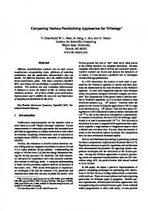
Figure 1: Example of a PdP node. The dashed arrows represent incoming, unprocessed packets. The solid arrows represent outgoing, processed packets. FE guest machines. The red and blue virtual networks require little packets processing power so that one FE is sliced into two FE guest machines, with one guest machine serving for the data plane of the red and blue virtual network, respectively. The green network requires much more processing power so two FE guest machines, each has all the processing power of one FE, are assigned to the green network. After packets being processed, they are returned to the MD with necessary tags and the MD dispatches those packets according to those tags.
PdP Node Architecture
A PdP node actually consists of a cluster of machines. One of the machines is the management host (denoted by MH) and there are multiple machines acting as the forwarding engines (denoted by FEs). A multiplexer/demultiplexer machine (denoted by MD), under the control of the MH, distributes incoming packets to FEs and merges the outgoing packets from FEs. Both the MH and the FEs are sliced into guest machines using operating system level virtualization mechanism [21]. A guest machine hosted in the MH is called a MH guest machine and a guest machine hosted in some FE is called a FE guest machine. We choose OS level virtualization because it is efficient and provides good isolation among guest machines. For one virtual network in PdP, its control plane runs in a MH guest machine. Depending on how much packet processing power a virtual network claims, one or more FE guest machines can be allocated to the virtual network to perform its data plane tasks. Slicing the FEs into how many FE guest machines and assigning which FE guest machines to each virtual network are important issues we need to consider. We will discuss this in detail when we present the design of the FE in Section 3.4. The MD in the PdP node coordinates multiple FE guest machines of the virtual networks hosted in the FEs. Once receiving a packet, the MD first decides which virtual network that packet belongs to and then sends it to corresponding FE guest machines for processing, such as address lookup and traffic shaping. After a packet is processed, it is returned to the MD. At that time, the packet is tagged with necessary information (e.g., the outgoing interface) for the MD to decide how to dispatch it. We show an example of the PdP node in Figure 1. It hosts three virtual networks, i.e., red, blue, and green. There are three MH guest machines, each of which runs the control plane of a virtual network. Packets belonging to virtual networks are classified and distributed from the MD to the
Figure 2 depicts the basic structure of a management host. The control plane of each virtual network runs in the guest machines hosted in the MH. For simplicity, we implement the multiplexer/demultiplexer inside the MH2 . The multiplexer/demultiplexer functions are implemented by the packet classifier and packet dispatcher running in the OS kernel of the MH. The packet classifier and dispatcher perform simple tasks and should process packets at high speed. For each incoming packet, the packet classifier first checks whether the packet belongs to a virtual network (e.g., the packet is encapsulated in UDP). If it does, the packet classifier further finds out which virtual network that packet belongs to and sends it to corresponding FE guest machine. The mapping between the virtual networks and their FE guest machines should be established when creating the virtual networks. After a packet is processed by the FE guest machine and sent back to the MH, it should be properly tagged. The packet dispatcher checks the tags of the packet to see whether this packet should be sent out or it should be delivered to a local MH guest machine. If it should be sent out, the packet dispatcher simply sends the packet to the outgoing interface (the packet has already been properly encapsulated by some FE guest machine and it has a tag to indicate the outgoing interface). If the FE guest machine labels a packet as local delivery (e.g., it is a routing update message), the
1
2
3.3
How many guest machines should be assigned to one virtual network and how much packet processing power one guest machine depend on the requirement the virtual network.
The Management Host and The Multiplexer/Demultiplexer
Note that the multiplexer/demultiplexer can be implemented using another dedicate machine or special purpose hardware.
11
routing software
routing software
mapping between virtual interfaces and physical interfaces
should be forwarded out by the dispatcher running in the MH. The packet processing functions of a virtual network run inside the guest machines so that the virtualization mechanism provides the isolation among different virtual networks. An alternative design option is if a virtual network exclusively uses one or more FEs, we can let its packet processing functions run in the privileged mode of the FEs for better performance (assuming the MD can match the aggregate speed of the FEs). However, opening the privileged mode of FEs necessitates human interactions in some situations, such as a buggy packet processing function hangs the FEs serving for a virtual network so a hard reboot is needed, which is not desirable in managing large scale shared substrates.
User space Kernel space mapping between FEs and virtual networks packet dispatcher
Interface to FEs
packet classifier all packets are sent to FEs
Routing updates are marked by the forwarding machines and sent to routing software
Interface to outside
Figure 2: The internal structure of a Management Host (MH).
3.4.2
packet dispatcher delivers it to the corresponding MH guest machine. Note that we use software to implement the MD function in commodity hardware for prototyping purpose. The MD function can be implemented by special purpose hardware such as Network Processor or NetFPGA for better performance. Since the MD function is not open to each virtual network for customization and programming, using special purpose hardware will not jeopardize the flexibility of PdP.
3.4
How to allocate the processing power of the FEs is of importance, because packet out-of-order resulting from parallelizing packet processing can impact the performance of the up-layer protocols such as TCP.
vnet1
The Forwarding Engine
FE1
The other important component in a PdP node is the FE. Here we first present the structure of the FE and then discuss the problem of how to allocate the processing power of the FEs to virtual networks.
3.4.1
Allocating the Processing Power of FEs
vnet2
vnet3
FE2
FE3
(a)
vnet1
vnet2
vnet3
FE2
FE3
Structure of FE
The structure of an FE is shown in Figure 3. Each FE is sliced into one or more guest machines using OS level virtualization as well. A packet belonging to a virtual network is delivered to the packet processing function running inside the a FE guest machine. The packet processing function processes each packet according to the control plane of that virtual network and marks the processed packet with a set of simple tags. The tags can be some fields in the header of a lightweight encapsulation mechanism used between the MH and the FEs. The tags include information such as whether the packet should be locally delivered, or how the packet
FE1
(b) Figure 4: vnet1 ∼ vnet3 get equal processing power in (a) and (b). In (a) vnet2 and vnet3 has two FE guest machines. In (b) vnet2 (and vnet3 ) has one FE guest machine only. Informally, the basic principle should be not slicing the FEs too finely to avoid such a situation that there are a lot of “fragmented” FE guest machines. For example, suppose there are three FEs (F E1 ∼ F E3 ) and they are allocated to three virtual networks (vnet1 ∼ vnet3 ). Slicing and allocating the FEs according to either Figure 4(a) or Figure 4(b) satisfies the processing power requirement of each virtual network. However, the slicing of FEs as in Figure 4(a) may cause vnet2 and vnet3 to have lots of out-of-order packets. Slicing the FEs as in Figure 4(b) is a better choice because all three virtual networks have their required processing power and none of them has the packet out-of-order problem3 . In order to minimize the impact of packet out-of-order to a virtual network, we should assign minimal number of FE guest machines to serve for its data plane. Suppose there are n virtual networks (vnet1 ∼ vnetn ) and vneti requires Ri processing power. Also suppose we have enough FEs in the PdP node and each FE has C processing power. Slicing the FEs and allocating their processing power can be for-
User space user mode Click
routing table, etc virtual interface
routing table, etc
user mode Click
virtual interface
Kernel space mapping virtual interfaces physical interface
physical interfaces
3
Note that if no single FE guest machine can satisfy the requirement of a virtual network, we have to assign multiple FE guest machines to that virtual network.
Figure 3: The internal structure of a Forwarding Engine (FE).
12
physical interface4 , and a virtual router forwards packet between those two interfaces. The classifier in the MH classifies packets belonging to different virtual networks based on the UDP port numbers (assuming the virtual links in a virtual network are UDP tunnels). If a virtual network has multiple FE guest machines, the classifier sends packets to them in a round-robin manner. The packet processing function, which runs in the FE guest machines, processes each packet, encapsulates the packet with proper UDP/IP header, labels the packet a tag to indicate the outgoing interface, and sends it back to the MH. According to the tag labeled to the packet, the dispatcher in the MH sends that packet out via either interface A or interface B. In this PdP node prototype, the proto type field in the Ethernet header is reused as the tag to indicate the outgoing interface.
mulated as a “bin packing problem”, which is NP-hard [13]. That is, if Ri = kC + ri , (ri < C), we should first allocate k FE guest machines to vneti and each of them has all the processing power of one FE. Then finding the minimum number of FEs to “pack” the n remainders (r1 ∼ rn ) is the classic bin packing problem. Considering that new virtual networks are created in PdP and old ones are removed from PdP, we develop an heuristic algorithm to decide the slicing and allocation of FEs in an online manner. Our algorithm adopts a heuristic similar to the “best fit” heuristic used in solving the bin packing problem. Algorithm 1 depicts the pseudocode of the algorithm. Algorithm 1: SliceAlloc(R) Input: R, the processing power requirement of a virtual network vnet. Output: The “best fit” slicing and assignment of FEs which satisfies the requirement of vnet. 1 r=R%C; 2 k=(R − r)/C; 3 for i = 0; i < k; i + + do 4 find an idle FE, create one guest machine with C processing power in it, assign that guest machine to vnet; 5 F E∗ = null; 6 min = BIG N U M ; 7 for F Ei ∈ all F Es AND availableP ower(F Ei ) > r do 8 if (availableP ower(F Ei ) − r) < min then 9 min = availableP ower(F Ei ) − r; 10 F E∗ = F Ei ; 11
4.
4.1
Experiment Setting
Figure 6 shows the testbed in our experiments. Two Linux PCs are connected by the router machine through Gbit Ethernet links, where the router machine is a PdP node. We test three settings in which the number of FEs varies from one to three. For comparison purpose, we also test the scenarios where the router machine is one Linux PC running user mode Click in its guest machine and running Click software router in kernel mode. All PCs have 2.4 ∼ 3.0 GHz single-core Pentium 4 CPU, 1G RAM, and Gbit Ethernet NICs.
create a guest machine in F E∗ with processing power r and assign it to vnet;
3.5
EXPERIMENT EVALUATION
This section evaluates the packet processing performance of PdP. We focus on IP forwarding but the basic conclusions of our experiments also apply to virtual networks using protocols other than TCP/IP. Our experiments show that the raw packet forwarding speed of PdP scales with the number of FEs and it can match the best known forwarding speed of software router running in commodity hardware.
A PdP Node Prototype Source
We have built a proof-of-concept PdP node prototype as shown in Figure 5. All machines are Linux PCs and we use OpenVZ [2] to slice the MH and the FEs. The packet classifier and dispatcher running inside the MH are implemented by kernel mode Click [4]. The packet processing function of each virtual network running in the FE guest machines is implemented by user mode Click.
A
Management host
B
…...
B
Destination
Note that the experiment results presented here is to show that the performance trend of PdP scales with the number of FEs. It can be expected that better results will be achieved if more powerful hardware are used in our experiment, such as PCs equipped with multi-core CPUs which are able to poll NICs with multiple virtual ring queues.
C
forwarding engine
Router
Figure 6: The experiment testbed.
Gbit Ethernet switch
forwarding engine
A
4.2
Packet Forwarding Speed
We first use UDP traffic to test the raw packet forwarding speed of PdP. We configure the routing table to have only two routes, which point to the source host and the destination host respectively. The source host runs the udpgen tool shipped with Click to send UDP packets to the destination host. The udpgen tool runs in kernel mode and can send out packets at very high speed. The destination host runs the
forwarding engine
Figure 5: A PdP node prototype. The PdP node prototype has two external physical interfaces, A and B. We assign two virtual interfaces to each virtual router hosted in this PdP node, one mapped to each
4
Note that this is for purpose of testing and prototyping. In reality, each virtual router hosted by the PdP node can have any number of virtual interfaces.
13
udpcount tool in Click to count the number of received UDP packets. We had the experiments in which we create multiple concurrent virtual networks. The aggregate forwarding speed of the PdP node, when the number of virtual networks varies from one to three, does not show noticeable difference. To save space, throughout this section we present only the results where there is only one virtual network. If it is not stated explicitly, each FE hosts only one guest machine and the FE guest machine has all the processing power of the FE. We configure the source host to send out 64-byte UDP packets at a fixed speed ranging from 10K packets per second (pps) to 1100K pps. The forwarding speed of the router machine, when it is a PdP node, user mode Click router, or kernel mode Click router, is plotted in Figure 7. We also plot the packet loss rate at the router machine in Figure 8.
Forwarding speed (Kpps)
450
packet loss rate becomes larger; the forwarding speed of user mode Click and PdP drops down but the kernel mode Click router maintains a constant forwarding speed. The reason is that the kernel mode Click sets the Ethernet interface into polling mode [20] so as to prevent the receive livelock [19]. On the contrary, the packets receiving and sending in user mode Click and PdP (in FE guest machines) are driven by the OS interrupt procedures. With increasing numbers of input packets, the interrupt processing can eventually starve all other system tasks, resulting in low forwarding speed [20]. If we make use of the polling mode support in native Linux driver, the forwarding of PdP (and the user mode Click) would maintain the peak speed even the input speed is much higher than its peak forwarding speed. We also test the forwarding performance of PdP in case of other two packet sizes, 512 bytes and 1500 bytes, in which we set the packet input speed to saturate the 1 Gbps link. For 512-byte packet, the maximum packet input speed is about 230K pps and the maximum packet input speed for 1500-byte packet experiment is about 80K pps. We plot the results in Figure 9 and Figure 10. Our tests show that the forwarding speed gets lower for larger packets but having more FEs still achieves faster forwarding speed. PdP node with three FEs can match the speed of kernel mode Click in both the 512-byte packets experiment and the 1500-byte packets experiment. Equipping the PdP node with two FEs instead of one can double its speed. However, increasing the number of FEs from two to three does not show proportional forwarding speed enhancement because of the bandwidth limit of Gbit Ethernet link.
user click 1-FE PdP 2-FE PdP 3-FE PdP kernel click
400 350 300 250 200 150 100 50 0 0
200
400
600
800
1000 250 Forwarding speed (Kpps)
Input speed (Kpps)
Loss rate (%)
Figure 7: Packet forwarding speed results in UDP traffic experiment.
100 90 80 70 60 50 40 30 20 10 0
200 150 100 50 0 user Click
user click 1-FE PdP 2-FE PdP 3-FE PdP kernel click
0
200
400 600 800 Input speed (Kpps)
one FE
two FEs
three FEs
kernel Click
Figure 9: Forwarding speed experiment results when the packet size is 512 bytes. The input speed for each experiment is set to saturate the 1 Gbps link.
1000
4.3
Figure 8: Packet loss rate results in UDP traffic experiment.
Forwarding with Large Routing Table
Note that in the above experiments, because the routing table has only two routes, the IP address lookup time is ignorable due to the “warm cache” effect [1]. To study the forwarding performance of PdP in case of large routing table, we download a BGP routing table from RouteViews [3] and extract about 170K IP prefixes. We repeat the above experiments with this large routing table. To avoid the warm cache effect, the source host sends out UDP packets with randomly selected unicast destination IP addresses. In the
As shown in Figure 7 and Figure 8, when the input speed is lower than certain threshold, the forwarding speed always increases proportionally as input speed increases and the loss rate remains to be zero. The peak forwarding speed of PdP is proportional to the number of FEs and the peak speed of PdP with three FEs matches the peak speed of kernel mode Click. After the input speed exceeds the threshold, the
14
80
Throughput (Mbps)
Forwarding speed (Kpps)
90 70 60 50 40 30 20 10 0 user Click
one FE
two FEs
three FEs
user Click
kernel Click
two FEs
three FEs
kernel Click
node having one, two, and three FEs, are shown in Table 1. When counting the number of packets, we ignore those ACK messages sent by the destination host to the source.
router machine, the nexthop of all routes (including the default route) is set to the destination host. The experiment results are plotted in Figure 11. We can see that PdP still performs better than the user mode Click software router and matches the speed of kernel mode Click. However, the forwarding speed gets lower when using large routing table, especially for 64-byte packets experiment. For large packets, the forwarding speed does not show much degradation because the input speed is slow (due to the link bandwidth limit) and the IP address lookup time is not the significant part in packet processing.
% of out-oforder pkts
one FE
two FEs
three FEs
0.31%
10.19%
13.02%
Table 1: Percentages of out-of-order packets when the PdP node has one, two, and three FE guest machines. The classifier in the MH distributes packets to FE guest machines in a round robin manner. When there are more than one FE guest machines, about 10% ∼ 13% packets are out-of-order packets and there is no significant difference between the experiments using two and three FE guest machines. Note that although considerable number of packets are out-of-order, as shown in Section 4.4, we still have decent TCP throughput. Next we evaluate how the strategy of the packet classifier running in the MH affects the packet out-or-order. We use two identical FEs in the PdP node and each FE hosts one guest machine. We tune the setting of OpenVZ so that one FE guest machines has 75% of the CPU cycles of an FE and the other FE guest machines has 50% of the CPU cycles of an FE. The packet classifiers uses two packet distributing strategies. One is sending packets in round-robin manner; the other is sending different number of packets based the allocated CPU cycles of the guest machines, i.e., for every 5 packets, sending packets 1, 3, 5 to the FE guest machine with 75% CPU cycles and sending packets 2, 4 to the FE guest machine with 50% CPU cycles. The results are presented in Table 2
TCP Throughput
So far the experiments using UDP traffic test only the raw packet forwarding speed of PdP. Most popular network applications use TCP protocol and the actual throughput achieved by TCP depends on more factors such as packet reordering, round trip time etc. In this experiment, we evaluate the performance of PdP in terms of TCP throughput. The router machine is configured with two routes in its routing table. An iperf server runs in the destination host and an iperf client running in the source host sends TCP traffic to the iperf server. We do not change any TCP-related parameters of iperf but use the default values. The TCP throughput is plotted in Figure 12. Our experiments show that PdP with one FE guest machine achieves similar TCP throughput as user mode Click IP router. Even the MH distributes packets to FE guest machines in a round-robin manner and there are a lot of out-of-order packets (as will be shown in Section 4.5), PdP with two or three FE guest machines demonstrates significant improvement of TCP throughput compared with user mode Click and PdP with one FE guest machine.
4.5
one FE
Figure 12: The TCP throughput experiment results.
Figure 10: Forwarding speed experiment results when the packet size is 1500 bytes. The input speed for each experiment is set to saturate the 1 Gbps link.
4.4
1000 900 800 700 600 500 400 300 200 100 0
% of out-oforder pkts
Packet Out-of-Order in TCP
round-robin
proportional
12.27%
10.02%
Table 2: Packet out-of-order when the classifier uses different strategies to distribute packets to FE guest machines.
Packet out-of-order is a challenging problem for parallel processing based systems. The following experiment is to quantify how PdP affects packet out-of-order in TCP. We use iperf to generate a TCP session and capture all the packets at the destination host. Then we use the Expert Info tool in wireshark [7] to analyze the out-of-order packets. The percentages of out-of-order packets, in case of the PdP
The results in Table 2 show that less out-of-order packets will occur if the packet classifier takes into account the packet processing power (CPU cycle is just one aspect of the
15
90
300
80
250 200 150 100 50 0
Forwarding rate (Kpps)
350
300
Forwarding rate (Kpps)
Forwarding rate (Kpps)
350
250 200 150 100 50 0
user Click
one FE
two FEs
three FEs
kernel Click
(a) 64-byte packet
70 60 50 40 30 20 10 0
user Click
one FE
two FEs
three FEs
kernel Click
user Click
(b) 512-byte packet
one FE
two FEs
three FEs
kernel Click
(c) 1500-byte packet
Figure 11: Packet forwarding speed in case of large routing table. (a) plots the peak packet forwarding speed. For (b) and (c), the packet input speed is set to saturate the 1 Gbit Ethernet link. packet processing power) of FE guest machines. Note that packet out-of-order is a rather complicated problem and it is not clear whether distributing packets based on the CPU cycles of a FE guest machine is the best strategy. We are actively investigating how other strategies affect the packet out-of-order and to what extent the up-layer protocol performance is impacted.
4.6
ing multiple guest machines working in parallel to achieve high speed packet processing. We have built a prototype of the PdP node. The performance measurement shows very promising results for both UDP and TCP traffic. PdP is still under extensive developing and there are many interesting and challenging research problems we are going to investigate. First, one of our ongoing work is to distribute packets to FE guest machines based on flow information (assuming that the virtual network uses TCP/IP), so as to mitigate the packet out-of-order problem. It is a challenge to design a classifier scalable to many virtual networks, each having lots of flows. We are investigating the possibility of having multiple dedicated machines to do the packet classification. Second, note that a virtual network may use data plane other than TCP/IP. In this case, we must open certain interfaces of the MD so that a virtual network can control the behavior of the packet classifier in MD, such as letting each virtual network define which bits identifying a flow. Third, although the MD in our current PdP prototype can process packets at high speed, it can still limit the throughput of a PdP node when the number of FEs increasing. It is an interesting problem to study how to organize multiple PdP nodes into a cluster and each PdP node works like an interface in the PdP “cluster router”, so that the overall throughput of the PdP cluster can scale.
Transmission Delay
As every packet needs to traverse two PCs in a PdP node, it introduces the overhead in terms of transmission delay. We use the following experiment to evaluate the transmission delay overhead of PdP. Here the source host in Figure 6 uses ping to send ICMP packets to the destination host. We record average round-trip-time (RTT) reported by ping and show the results in Table 3.
RTT (ms)
user Click 0.208
PdP 0.296
kernel Click 0.132
Table 3: The round trip time experiment results. From the results in Table 3 we can see that one PdP node adds about 0.17ms additional delay to the RTT, compared with the RTT of the kernel mode Click router. The addition delay is 0.09ms compared with the RTT of user mode Click router. According to the measurement study in [17], most hosts in Internet are about 14 hops away from a university probing site and the average RTT from those hosts to the probing site is about 80ms. Therefore, if PdP is widely deployed in Internet and each PdP node adds 0.17ms additional RTT delay, the total additional RTT delay would be about 2.4ms, which is ignorable considering an 80ms average RTT.
5.
6.
ACKNOWLEDGEMENTS
The authors are grateful to the anonymous reviewers for the many helpful comments and suggestions. This work is partially supported by U.S. NSF grants CNS-0626618 and CNS-0831940. Dong Yin is supported by China State Scholarship Fund CSC-2008629080.
7.
REFERENCES
[1] Click element documentation. http://www.read.cs. ucla.edu/click/elements/iproutetable. [2] OpenVZ. http://www.openvz.org/. [3] Route Views Project. http://www.routeviews.org. [4] The Click Modular Router. http://read.cs.ucla.edu/click/. [5] VINI. http://www.vini-veritas.net/. [6] The Virtual Router Project. http://nrg.cs.ucl.ac.uk/vrouter/.
CONCLUSION AND FUTURE WORK
In this paper we present PdP, a full programmable and high speed virtual network platform. PdP is built from costefficient commodity hardware and open source software. A virtual network hosted in PdP can have complete control over its control plane and data plane without interfering other virtual networks. The key ideas behind PdP are twofold: running virtual network control plane and data plane in guest machines for better isolation and flexibility; hav-
16
[7] wireshark. http://www.wireshark.org. [8] Xen. http://www.xen.org/. [9] K. Argyraki, S. Baset, B.-G. Chun, K. Fall, G. Iannaccone, A. Knies, E. Kohler, M. Manesh, S. Nedevschi, and S. Ratnasamy. Can software routers scale? In PRESTO ’08: Proceedings of the ACM workshop on Programmable routers for extensible services of tomorrow, 2008. [10] A. Bavier, N. Feamster, M. Huang, L. Peterson, and J. Rexford. In VINI veritas: realistic and controlled network experimentation. In SIGCOMM ’06: Proceedings of the 2006 conference on Applications, technologies, architectures, and protocols for computer communications, 2006. [11] S. Bhatia, M. Motiwala, W. Muhlbauer, Y. Mundada, V. Valancius, A. Bavier, N. Feamster, L. Peterson, and J. Rexford. Hosting virtual networks on commodity hardware. Technical report, Princeton University, Nov. 2007. [12] S. Bhatia, M. Motiwala, W. Muhlbauer, Y. Mundada, V. Valancius, A. Bavier, N. Feamster, L. Peterson, and J. Rexford. Trellis: A platform for building flexible, fast virtual networks on commodity hardware. In Proceedings of ROAD’ 08: 3rd International Workshop on Real Overlays and Distributed Systems, Dec. 2008. [13] P. Crescenzi and V. Kann. A compendium of NP optimization problems. online document: http://www.nada.kth.se/~viggo/problemlist/. [14] N. Egi, A. Greenhalgh, M. Handley, M. Hoerdt, F. Huici, and L. Mathy. Fairness issues in software virtual routers. In PRESTO ’08: Proceedings of the ACM workshop on Programmable routers for extensible services of tomorrow, 2008. [15] N. Egi, A. Greenhalgh, M. Handley, M. Hoerdt, F. Huici, and L. Mathy. Towards high performance
[16]
[17]
[18]
[19]
[20]
[21]
[22]
17
virtual routers on commodity hardware. In CoNEXT ’08: Proceedings of the 4th ACM International Conference on emerging Networking EXperiments and Technologies, 2008. N. Egi, A. Greenhalgh, M. Handley, M. Hoerdt, L. Mathy, and T. Schooley. Evaluation xen for virtual routers. In PMECT’07: Proceedings of International Workshop on Performance Modeling and Evaluation in Computer and Telecommunication Networks, August 2007. A. Fei, G. Pei, R. Liu, and L. Zhang. Measurements on delay and hop-count of the internet. In IEEE GLOBECOM’98 - Internet Mini-Conference, 1998. E. Keller and E. Green. Virtualizing the data plane through source code merging. In PRESTO ’08: Proceedings of the ACM workshop on Programmable routers for extensible services of tomorrow, 2008. J. C. Mogul and K. K. Ramakrishnan. Eliminating receive livelock in an interrupt-driven kernel. ACM Trans. Comput. Syst., 15(3):217–252, 1997. R. Morris, E. Kohler, J. Jannotti, and M. F. Kaashoek. The click modular router. SIGOPS Oper. Syst. Rev., 33(5):217–231, 1999. S. Soltesz, H. P¨ otzl, M. E. Fiuczynski, A. Bavier, and L. Peterson. In Proceedings of EuroSys ’07: Proceedings of the 2nd ACM SIGOPS/EuroSys European Conference on Computer Systems 2007, pages 275–287, New York, NY, USA, 2007. ACM. J. S. Turner, P. Crowley, J. DeHart, A. Freestone, B. Heller, F. Kuhns, S. Kumar, J. Lockwood, J. Lu, M. Wilson, C. Wiseman, and D. Zar. Supercharging planetlab: a high performance, multi-application, overlay network platform. In SIGCOMM ’07: Proceedings of the 2007 conference on Applications, technologies, architectures, and protocols for computer communications, 2007.