transformation relating the 2 images. Multiresolution splining is then used to blend the side profiles with the frontal image thereby generating a composite face.
Appeared in Proc. of 4th IEEE Workshop on Automatic Identification Advanced Technologies (AutoID), (Buffalo, USA), pp. 63-68, October 2005.
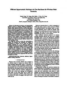
Performance Enhancement of 2D Face Recognition via Mosaicing Richa Singh, Mayank Vatsa, Arun Ross, Afzel Noore West Virginia University, Morgantown, WV 26506 {richas, mayankv, ross, noore}@csee.wvu.edu
Abstract We describe a face mosaicing scheme that generates a composite face image during enrollment based on the evidence provided by frontal and semi-profile face images of an individual. Face mosaicing obviates the need to store multiple face templates representing multiple poses of a user’s face image. In the proposed scheme, the side profile images are aligned with the frontal image using a terrain transform that exploits neighborhood properties to determine the transformation relating the 2 images. Multiresolution splining is then used to blend the side profiles with the frontal image thereby generating a composite face image of the user. A local binary pattern matching algorithm is used to compare an input face image with the template face mosaic. Experiments conducted on a small dataset of 27 users indicate that face mosaicing as described in this paper offers significant benefits by accounting for the pose variations commonly observed in face images.
1. Introduction The problem of 2D face recognition continues to pose several challenges even after 30 years of research in this field [1]. Most 2D face recognition algorithms described in the literature are sensitive to changes in illumination, pose, facial expressions/accessories, etc. Designing pose-invariant algorithms is especially very challenging as discussed in the FRVT (Face Recognition Vendor Test) 2002 report [2]. Several methods have been suggested to address the problem of pose variations including the use of morphable models [15], 3D facial imaging [16], multiple templates [18], and multiclassifier fusion [17]. In this work we propose the use of a mosaicing scheme to generate a 2D face mosaic of an individual during enrollment that can be successfully used to match various poses of a person’s face. Mosaicing uses the frontal and side-profile face images (2D) of a user to generate an extended 2D image. The goal is to adequately summarize the 3D surface of an individual’s face in a 2D plane, without attempting to compute the 3D structure of the face. This avoids the complexity of generating 3D structure information from multiple
(registered) 2D images. Mosaicing also obviates the need to store multiple templates of a user during enrollment thereby optimizing storage demands and processing time. The potential of mosaicing facial images has been examined by a few researchers. Yang et al. [5] proposed an algorithm to create panoramic face mosaics. Their acquisition system consists of five cameras that simultaneously obtain five different views of a subject’s face. In order to determine the corresponding points in multiple face views, the authors place ten colored markers on the face. Based on these control points, their algorithm uses a series of fast linear transformations on component images to generate a face mosaic. Finally, a local smoothing process is carried out to smooth the mosaiced image. Two different schemes were used to represent the panoramic image: one in the spatial domain and the other in the frequency domain. The frequency representation resulted in an identification accuracy of 97.46% while the spatial representation provided 93.21% accuracy on a database of 12 individuals. Liu and Chen [6] proposed a face mosaicing technique that uses a statistical model to represent the mosaic. Given a sequence of face images captured under an orthographic camera model, each frame is unwrapped onto a certain portion of the surface of a sphere via a spherical projection. A minimization procedure using the Levenberg-Marquardt algorithm is employed to optimize the distance between an unwrapped image and the sphere. The representational model (statistical) comprises of a mean image and a number of eigen-images. The novelty of this technique is (a) the use of spherical projection, as opposed to cylindrical projection, which works better when there is head motion in both the horizontal and vertical directions, and (b) the computation of a representational model using both the mean image and the eigen-images rather than a single template image. Although the authors state that this method can be used for face recognition, no experimental results have been presented in the paper. In [7], the authors have proposed another algorithm in which the human head is approximated with a 3D ellipsoidal model. The face, at a certain pose, is viewed as a 2D projection of this 3D
Appeared in Proc. of 4th IEEE Workshop on Automatic Identification Advanced Technologies (AutoID), (Buffalo, USA), pp. 63-68, October 2005.
ellipsoid. All 2D face images of a subject are projected onto this ellipsoid via geometrical mapping to form a texture map which is represented by an array of local patches. Matching is accomplished by adopting a probabilistic model to compute the distance of patches from an input face image. The authors report an identification accuracy of 90% on the CMU PIE database. Face mosaicing has also been used in other fields such as facial animation and rendering [7], [9], 3D face image generation [10], etc. However, these algorithms generate the face mosaic using complex models which do not necessarily preserve the biometric features of the face. The primary focus of this work is the implementation of a simple mosaicing and matching scheme for face recognition that is robust to variations in pose. It is assumed that multiple shots of a user’s face image representing various poses are available at the time of enrollment. First, the face is segmented from each image using the Gradient Vector Flow technique [12] and then normalized using alignment techniques proposed in the following sections. Mosaicing is accomplished using multi-resolution splines based on Gaussian and Laplacian pyramids [11]. Multiresolution splines also perform blending as an integral part of mosaicing thereby offering some inherent advantages. The performance of the mosaiced image is evaluated using a texture-based face recognition algorithm ([13], [14]). Experiments indicate that multiresolution splines preserve the textural features of the face necessary for recognition while enhancing the performance of face recognition in terms of matching accuracy, and time and memory requirements.
2. Face Mosaicing Face mosaicing, as described in this paper, consists of three major steps: (1) Determining the pair-wise transformation necessary to align the faces obtained during enrollment; (2) Generating a mask; and (3) Stitching and blending.
2.1. Transformation and Alignment of Faces Before mosaicing the images, it is necessary to transform the multiple images obtained during enrollment into a common plane. Here, we assume that 3 images are made available during enrollment: (a) frontal, (b) semi-left and (c) semi-right. Also, the side profile images are assumed to have a rotation of at least 300 with respect to the frontal image in order to ensure that sufficient information about the face is available.
Since the camera-to-face distance is fixed in all 3 images, a transformation to handle rotation, alignment and deformation due to various facial expressions is computed. Step 1. Three blank images of size 256 x 256 are first created. Step 2. The coordinates of the eyes and nose objects are determined in the frontal face image (this can be done using any standard eye-nose finding algorithm). The frontal image is placed on one of the blank image spaces such that its nose coordinates are at the center, i.e., (128, 128) (Figure 1(a)). Step 3. Similarly, the three coordinates (two eyes and one nose) are located in the side-profile face images. Based on their respective nose coordinates, these images are placed in the two remaining blank image spaces (Figure 1(b), 1 (c)). Step 4. Based on the positions of the eyes and the nose, a terrain transform is used to align each of the side profile images with the corresponding frontal face image as shown in Figures 2 and 3.
(a) (b) (c) Figure 1: Image initialization. (a) Frontal image placed on the blank space (nose coordinates are at (128, 128)); (b) and (c) The two profile images in the 256x256 image space. Terrain transform has been extensively used in the computer graphics community. This transformation was adopted in this work since the neighborhoods of two corresponding points are never rigorously identical. Typically, in face images there are differences in geometry and relative distortions caused by the local relief of the object, i.e. the terrain effect. Furthermore, even in the absence of geometrical distortions, subpixel shifting can occur. This problem can be addressed by geometrically transforming the neighborhood area of one image with respect to the other. Such a transform is not known a priori and depends on the unknown shape of the terrain (neighborhood). Let F1 and F2 be the two facial profiles; the goal is to transform F2 as per the local geometry of F1. Let f k1 and f k be the local points (i.e., eyes and nose) on F1 and F2, respectively, where k is the number of local features (i.e., 3). Next, a local rectangular region is associated with each of these features. The local eye region is centered about the eye and is defined based on its distance (both horizontal and 2
Appeared in Proc. of 4th IEEE Workshop on Automatic Identification Advanced Technologies (AutoID), (Buffalo, USA), pp. 63-68, October 2005.
vertical) from the edge of the face as illustrated in Figure 2. Thus, it varies across individuals and poses. The nose region, on the other hand, is 50 pixels wide and 50 pixels long (38 pixels above the nose and 12 pixels below it). The dimensions of these regions have been empirically determined based on experiments conducted on a small dataset. The terrain transform, between two images, operates by determining the transformation that results in the maximum correlation between two corresponding local regions. Only rotation (R), translation (T) and scaling (S) have been considered in this work. Thus, the following criterion function, C(R, T, S), is used to derive the optimal transformation parameters. k
∑ pρ i
C ( R = r , T = t , S = s) =
i =1 k
∑p
2 i
.
(1)
ensure that salient facial features (viz., eye, nose, chin, face contour, etc.) are not distorted during the blending process. In this regard we make the following two observations: (a) the seam in the upper region of the face is mostly vertical; (b) the seam in the lower portion of the face has to accommodate the user’s chin which is slightly slanted. Thus, we develop a binary mask that defines the regions pertaining to the frontal and side profiles to be retained in the composite image. The shape and size of the mask varies across individuals and depends on the rotation of the face. Thus, this is a dynamic mask generated at runtime. Figure 4 shows an example of the mask generated from the left and right profiles of a user. Note that the mask presents a strict boundary between the 2 images. In order to ‘soften’ this, we subject the mask to a Gaussian weighting function.
i
i =1
Here, ρi2 denotes the correlation of the corresponding local regions at a particular transformation (r, t, s), and pi = 1 if the corresponding features are available in both images (0, otherwise). A small range of (r, t, s) values were used in the search process and, hence, an exhaustive set of possibilities were considered to derive the optimal (r*, t*, s*) values. Figure 3 shows the transformed images with respect to the frontal face image.
Figure 2: The local regions considered in a pair of images.
(a) (b) (c) Figure 3: Effect of applying the terrain transform. (a) Frontal Image; (b) and (c) Transformed profile images with respect to the frontal image.
2.2. Mask Generation Once the alignment between an image pair is determined, a blending procedure is used to create a composite image. The challenge in face mosaicing is to
Figure 4: The masks generated from two profile images.
2.3. Stitching and Blending For combining two images we use Multiresolution Splines [11]. Image splining can be done based on simple spline weighting function, but the quality of the stitched image depends on the step size that is chosen. A large step size may lead to blurring whereas a small step size might result in discontinuities at the boundary. To overcome this problem, Burt and Adelson [11] used multiresolution splines to determine different step sizes for various frequency components. In this technique, a sequence of low pass filtered images is obtained by iteratively convolving each image with a 2D Gaussian filter kernel. The resolution of the image between successive iterations is reduced and, therefore, the Gaussian kernel operates on a reduced version of the original image each time. The resultant images G0, G1, …,GN may be viewed as a ‘pyramid’ structure with G0 having the highest resolution (lowermost level) and GN having the lowest resolution (uppermost level). Let {w(m,n)}, m,n = 1..5, represent the Gaussian kernel. Then this process can be summarized by the following equation:
Gl = Reduce [Gl −1 ] , 0 < l < N, i.e., Gl = ∑
5
∑ w(m, n)G
m ,n=1
l −1
(2i + m,2 j + n) .
(2) (3)
Appeared in Proc. of 4th IEEE Workshop on Automatic Identification Advanced Technologies (AutoID), (Buffalo, USA), pp. 63-68, October 2005.
Figure 5: Levels in the Gaussian Pyramid expanded to the original size to see the effects of the low pass filter. The effect of convolution (Figure 5) is to blur the image, thereby reducing the filter band limit by an octave from level to level whilst reducing the sample density by the same factor. The multiresolution spline as described in [11] requires band pass images (as opposed to low pass images). Band pass images are computed by interpolating the image in each level of the pyramid and then subtracting it from the next lowest level. This results in a sequence of band pass images that can be viewed as a Laplacian pyramid (L0,L1,…,LN). The term Laplacian is used since the Laplacian operator resembles the difference of Gaussian-like functions. These band-pass images are really a result of convolving the difference of two Gaussians with the original image. The steps used to construct this pyramid can also be used to exactly recover the original image. The process described above may be summarized as follows:
Ll = Gl − Expand [Gl +1 ] , 0 < l < N, Gl ,k (i, j ) = 4∑
2
∑
m , n = −2
Gi ,k −1 (
2i + m 2 j + n . ) , 2 2
(4) (5)
Here, the Expand[.] operator interpolates a lowresolution image to the next highest level. Note that Gl,k in (5) denotes ‘expanding’ Gl k number of times. Various features of the face are segregated by scale in the different levels of the pyramid. Hence, the textural features of the face are preserved over multiple levels of the pyramid. Let LA and LB represent the Laplacian pyramids of the two images that are being splined. Let GR be the pyramid associated with the Gaussianweighted mask discussed in Section 2.2. The multiresolution spline, LS, is then computed as, LSl (i, j ) = GRl (i, j ) LAl (i, j ) + (1 − GRl (i, j )LBl (i, j ) ,
(6)
where l is the level of the pyramid. The splined images at various levels are expanded and summed together to obtain the final face mosaic as shown in Figure 6.
3. Experimental Results
The performance of the proposed scheme was tested on a subject set from West Virginia University (WVU) as well as the database used in [5]. The WVU database consists of images of fifteen individuals (9 images per individual) obtained across three different sessions without any constraint on illumination and pose. The face database used in [5] consists of images from twelve individuals (12 images per individual) across four different sessions1. Figure 7 shows a few examples of face mosaics obtained using the proposed algorithm.
Figure 6: The left, frontal and right profile face images along with the mosaiced face image. To validate the performance of mosaicing we used the face matching algorithm described in [14]. For each of the 27 users, a set of 3 images (1 frontal and 2 semiprofile) were used as templates (S1) while the remaining images (S2) were used to test the matching performance of the system. The images in S1 were used to generate the face mosaic for an individual. The following experiments were conducted: (a) Each image in S2 was compared against each of the frontal templates in S1 to generate match scores (b) Each image in S2 was compared against a set of 3 images in S1 (pertaining to a single user) to generate 3 different match scores. These scores were combined using the sum rule and the min rule. (c) Each image in S2 was compared against the face mosaic generated using the 3 template images of a user in S1 in order to generate match scores. A mosaiced face image contains all the features in a face while the frontal and the side profile images have only a limited number of features. Therefore, existing face recognition algorithms such as appearance-based or feature-based may not be able to operate on mosaiced images reliably. So we use a local representation of the textural features in order to account for variations in the number of features across different images and individuals. The query image (2D non-mosaiced) is registered on a 256x256 plane using the nose coordinate. The local features are then extracted from the face, converted into polar coordinates and convolved with a 2D log polar Gabor 1
The original dataset consisted of 20 images per individual; however, we used only a subset of this in our experiments.
Appeared in Proc. of 4th IEEE Workshop on Automatic Identification Advanced Technologies (AutoID), (Buffalo, USA), pp. 63-68, October 2005.
wavelet [14]. The phase information of these local textural facial features is encoded to form a binary template which is used in a sliding weighted matching scheme. This scheme gives more emphasis to features that are matched with higher confidence. For example, if a frontal face is matched with a mosaiced face, the sliding weighting scheme assigns more weight to the eyes, nose, and mouth, whereas if a profile face is used, the ear, eye and nose are given prominence. Figure 8 illustrates the steps involved in comparing the mosaiced face image with a non-mosaiced face image. Figure 9 shows the ROC plot corresponding to these experiments; it is observed that the performance of face recognition is significantly improved with the use of mosaicing technique. We also evaluated the time complexity of the algorithm. Recognition with mosaiced image took 1.11 CPU-time2 while the sum/min rule based approach took 1.74 CPU time. The verification time using the mosaiced image is less because the mosaicing algorithm takes 0.53 CPU-time while verification takes 0.58 CPU-time; however, in the sum/min rule case we have to execute the verification algorithm three times before invoking the sum/min rule. Memory requirement without mosaicing is 3 x m bytes where as it is approximately 1.1 x m bytes for the mosaiced image (m is the number of bytes needed to store 1 profile image). These results show that the mosaicing process enhances the performance of face recognition algorithm whilst reducing the memory requirement and the matching time. In Table 1 we compare the proposed algorithm with two other algorithms described in the literature.
Table 1: A brief comparison of three different mosaicing schemes. Yang et.al. [5]
Liu & Chen [7]
12 Affine using points
68 Affine using triangles
Mosaicing
Concatenation
Geometrical mapping
Representation
Spatial: PCA Frequency: FFT amplitude
Statistical model
Subjects Registration
Local binary pattern
Authors are grateful to Prof. Herve Abdi and Dr. Fan Yang for providing the face database [5]. Thanks to all the volunteers who participated in this project.
We have described a face mosaicing procedure that creates a composite image of an individual’s face by blending the frontal and side profile views. The proposed scheme utilizes terrain transforms to register the views and multiresolution splines to blend the views together. The blending process is observed to be robust, i.e., it does not distort the salient features of the face. Experimental results suggest that face mosaicing is a good alternative to storing multiple views of a user’s face. Currently, we are examining ways to improve the registration process. We are also looking at novel algorithms to perform matching in the mosaic domain. Experiments will then be conducted on larger datasets in order to demonstrate the efficacy of the technique. Figure 7: Examples of mosaiced face templates. For two of the subjects multiple mosaics are shown. The CPU-time was calculated in a MATLAB environment.
12 + 15 Affine using regions Multiresolution splines
5. Acknowledgements
4. Summary and Future Work
2
Proposed algorithm
Appeared in Proc. of 4th IEEE Workshop on Automatic Identification Advanced Technologies (AutoID), (Buffalo, USA), pp. 63-68, October 2005.
6. References [1] W. Zhao, R. Chellappa, A. Rosenfeld, and P.J. Phillips, “Face Recognition: A Literature Survey”, ACM Computing Surveys, 35(4): 399 – 458, December 2003. [2] P.J. Phillips, P. Grother, R.J Micheals, D.M. Blackburn, E. Tabassi, and J.M. Bone, “FRVT 2002: Evaluation Report”, 2003. [3] N.K. Ratha, J.H. Connell and R.M. Bolle, “Image mosaicing for rolled fingerprint construction”, Proceedings of ICPR, 2:1651 – 1653, August 1998. [4] A. Jain, A. Ross, “Fingerprint mosaicking”, Proceedings of ICASSP, 4: IV-4064 – IV-4067, May 2002. [5] F. Yang, M. Paindavoine, H. Abdi, and A. Monopoly, “Development of a fast panoramic face mosaicing and recognition system”, Optical Engineering, 44, 2005, (in press). [6] X. Liu and T. Chen, “Geometry-assisted statistical modeling for face mosaicing”, Proceeding of IEEE ICIP, 2: 883 – 886, September 2003. [7] X. Liu and T. Chen, “Pose-Robust Face Recognition Using Geometry Assisted Probabilistic Modeling”, Proceedings of CVPR, 1:502 – 509, June 2005. [8] G. Borshukov and J.P. Lewis, “Realistic human face rendering for – the matrix reloaded”, http://www.virtual cinematography.org/publications/acrobat/Face-s2003.pdf). [9] S.B. Kang, “A Survey of Image-based Rendering Techniques”, Cambridge Research Laboratory Technical report - CRL 97/4, 1997. [10] K.W. Bowyer, K. Chang, and P. Flynn, “A survey of 3d and multi-modal 3d+2d face recognition”, Notre Dame Department of Computer Science and Engineering Technical Report, 2004. [11] P.J. Burt and E.H. Adelson, “A multiresolution spline with application to image mosaics”, ACM Transaction on Graphics, 2: 217-236, 1983. [12] C. Xu and J.L. Prince, “Snakes, Shapes, and Gradient Vector Flow”, IEEE Transactions on Image Processing, 7(3): 359-369, March 1998. [13] R. Singh., M. Vatsa, and A. Noore, “Textural feature based face recognition for single training images”, IEE Electronics Letters, 41(11): 23 – 24, May 2005. [14] R. Singh, M. Vatsa, and A. Noore, “Face Recognition using Scanned Images”, Pattern Recognition, 2005 (Submitted). [15] V. Blanz, S. Romdhami, and T. Vetter, “Face identification across different poses and illuminations with a 3D morphable model”, Proceedings of International Conference on Automatic Face and Gesture Recognition, 202-207, May 2002. [16] K.I. Chang, K.W. Bowyer, and P.J. Flynn, “An evaluation of multi-modal 2D+3D face biometrics”, IEEE Transactions on Pattern Analysis and Machine Intelligence, 27(4): 619-624, 2005. [17] X. Lu, Y. Wang, and A.K. Jain, “Combining Classifiers for Face Recognition”, Proceedings of IEEE International Conference on Multimedia & Expo, III:13-16, July 2003. [18] U. Uludag, A. Ross, and A.K. Jain, “Biometric Template Selection and Update: A Case Study in Fingerprints”, Pattern Recognition, 37(7): 1533-1542, July 2004.
Mosaiced Face
Registered Non Mosaiced Face
Local Feature Extraction (a features)
Local Feature Extraction (b features)
Texture Encoding with 2D log polar Gabor
Texture Encoding with 2D log polar Gabor
Sliding Weighted Matching Scheme
Matching Score
Figure 8: Block diagram of the matching scheme that was used to compare face images (mosaiced and profile).
Figure 9: Performance evaluation using the proposed scheme. The min fusion rule is observed to perform well also. However, the mosaiced image resulted in the best performance.