International Journal of Computer Science, Engineering and Information Technology (IJCSEIT), Vol.1, No.2, June 2011
PERFORMANCE ENHANCEMENT OF DYNAMIC CHANNEL ALLOCATION IN CELLULAR MOBILE NETWORKS BASED ON CARRIER-TO-NOISE INTERFERENCE RATIO Md. Sadek Ali1, M. A. Masud2, Md. Shariful Islam1, Md. Alamgir Hossain1 1
Dept. of Information & Communication Engineering Islamic University, Kushtia 7003, Bangladesh. 2 Dept. of Computer Science & Information Technology Patuakhali Science and Technology University, Patuakhali, Bangladesh. E-mail :{ sadek_ice, afmsi76, alamgir_ict}@yahoo.com,
[email protected]
ABSTRACT In cellular mobile communication system the existing dynamic channel allocation scheme suffer from high blocking probability and forced termination probability. To mitigate this problem, in this paper we evaluated the performance of dynamic channel allocation scheme based on carrier-to-noise interference ratio. In our system model, uplink power strength from a call-initiating user to the base station is examined. This power is provided by the carrier-to-noise ratio (C/N). The channel search is conducted in the repeated channel numbers of that cell based on the carrier-to-noise ratio so that this system provides the low blocking probability and initiates large number of calls in dynamic channel allocation environment. We have presented the momentous performance in blocking probability and forced termination probability through this research.
KEYWORDS Dynamic Channel Allocation (DCA), Blocking Probability (BP), Forced Termination Probability (FTP).
1. INTRODUCTION Technological advances and rapid development of handheld wireless terminals have facilitated the rapid growth of wireless communications and mobile computing. Mobile computing uses cellular/wireless communication network [1]. The tremendous growth of the wireless/mobile users’ population coupled with the bandwidth requirements of multimedia applications requires efficient reuse of the scarce radio spectrum allocated to wireless/mobile communications. Efficient use of radio spectrum is also important from a cost-of-service point of view, where the number of base stations required serving a given geographical area. A reduction in the number of base stations and hence a reduction in the cost-of-service can be achieved by more efficient reuse of the radio spectrum. The basic prohibiting factor in radio spectrum reuse is interference caused by the environment or other mobiles. Interference can be reduced by deploying efficient radio subsystems and by making use of channel assignment techniques. However, co-channel interference caused by frequency reuse is the most restraining factor on the overall system capacity in the wireless networks and the main idea behind channel assignment algorithms is to make use of radio propagation path-loss characteristics in order to minimize the Carrier-toInterference ratio (CIR) and hence to increase the radio spectrum reuse efficiency[2]. Many channel allocation schemes are proposed in the literature, the purpose of these schemes is to assign channels in such a way so that channel utilization is maximized at the same time DOI : 10.5121/ijcseit.2011.1202
16
International Journal of Computer Science, Engineering and Information Technology (IJCSEIT), Vol.1, No.2, June 2011
maintaining the voice quality. When mobile host needs a channel to support a call it sends request message to mobile service station (MSS) in its cell, the MSS tries to assign a channel to the mobile host (MH) using channel allocation scheme. The channel allocation schemes can be classified in three categories, Fixed channel allocation (FCA), Dynamic channel allocation (DCA) and Hybrid channel allocation (HCA). In fixed channel allocation [3][4], a set of channel is permanently allocated to each cell of the system. When user requests a channel for communication, it search the free channel in its own cell, if the free channel is available assigned to the user otherwise the request will be blocked. In dynamic channel allocation [4][5] implies that channels are allocated dynamically as new calls arrive in the system and is achieved by keeping all free channels in a central pool. This means when a call is completed, the channel currently being used is returned to the central pool. In hybrid channel allocation [3][4], few channels are permanently allocated to each cell and the remaining channels are allocated dynamically. The performance of the hybrid channel allocation schemes is intermediate between fixed and dynamic channel allocation schemes. The dynamic channel allocation schemes are divided into two types centralized and distributed. In Centralized dynamic channel allocation (CDCA) schemes [4][6], a channel is selected for a new call from a central pool of free channels, and a specific characterizing function is used to select one among available free channels. The simplest scheme is to select the first available free channel that can satisfy the reuse distance. Also that free channel can be picked which can minimize the further blocking probability in the neighborhood of the cell that needs an additional channel. Dynamic channel allocation scheme proposed by Gouhong Cao et. al. [7] has used a resource-planning model, uses cluster size 9 in which the set of cells in the system model is partitioned into 9 disjoint subsets. Every cell in a disjoint subset is in the minimum reuse distance. The numbers of channel are also divided into 9 disjoint sets of channels. The each partitioned group assigned a channel group. DCA proposed by Gouhong Cao et. al. [7] uses the cluster size 9, which contains 30 interfering neighbors. When a channel needs by the cell has to send the request message to all its interference neighbors, thus the message complexity of the algorithm is high. This high message complexity of algorithm needs to develop new system model, which reduces message complexity to some extent. In cellular mobile communication system the existing dynamic channel allocation scheme suffer from high blocking probability and forced termination probability. To mitigate this problem, in this paper we evaluated the performance of dynamic channel allocation scheme based on carrier-to-noise interference ratio. In our system model, uplink power strength from a call-initiating user to the base station is examined. This power is provided by the carrier-to-noise ratio (C/N). The rest of the paper is organized as follows. Problem stated in section two. In section three shows the detailed system model. Section four describes flowchart of the system. Simulation results are described in section five. Finally, section six concludes the paper.
2. PROBLEM FORMULATION In the model, we first input coordinates of the user’s position and the base station to obtain the path loss value and then add shadowing attenuation value. After that we obtain the attenuation value of the desired signal and from this value we can obtain the carrier-to-noise ratio (C/N) of the signal received by the base station. After calculating the value of C/N, we search for an available channel that is not in use, and that satisfies the interference conditions of the carrierto-noise plus interference ratio C/ (N+I).The channel search is conducted in the repeated channel numbers of that cell, so that the provided number of channels is examined in its entirety. If another user is allocated to the same channel, we calculate the interference from that user. We also calculate the attenuation value of the interference signal from this neighboring cell. 17
International Journal of Computer Science, Engineering and Information Technology (IJCSEIT), Vol.1, No.2, June 2011
Finally, we examine if the achieved value of the C/ (N+I) can satisfy the interference condition, that is if it is greater than the C/ (N+I) threshold, a call is accepted, and a channel is allocated to the user. The output is also allocated to the user as its call holding time, which provides the time the call is finished. If the inference condition is not satisfied, we regard such a call as being blocked and the number of blocked calls is counted. We also checked the interference conditions for connected users in every period. This routine is conducted in a similar way to channel assignment, and the C/ (N+I) of allocated channel for each connected user is examined. If the C/(N+I) of the channel is not satisfied, the user releases a currently allocated channel and tries to find an alternative channel in just the same way as channel assignment. At this point, if a channel condition is not satisfied, such event is not regarded as blocking but as the forced termination of a call.
3. SYSTEM MODEL 3.1. Resource Planning We divided the total geographical area into 19 cells. In this model cluster size 19 and channel number 190 and each cell contains 10 channels. In the system two techniques are used such as cell layout and cell wrapping. Discrete meshes are used to allocate a certain amount of traffic into the specially shaped area such as hexagonal cell [8]. Each call generation is subject to the Poisson distribution with its mean arrival rate for each user. Every initiated call has its own call holding time that is subjected to the exponential distribution mean value of holding time. Shadowing is assumed to be subject to log normal distribution.
3.2. Performance Measures Before giving a detailed explanation about our simulation programs, we describe the performance measures in our system. We are focusing on two measures, blocking probability is defined as the statistical probability that a new call will fail to find suitable channels that satisfy the C/(N+I)Ratio condition is given in equation1.
-------------------- (1)
Here, α is the path loss factor, A is a proportional coefficient, Pi is the transmitted power of user Ti ,Di is the distance between user Ti and base station Ro .In addition, i is the distortion caused by shadowing between Ti and Ro, the value of which is expressed by decibel in equation 1. Although the blocking probability is the measure pertaining to new calls, a connected call can be interrupt before it finishes due to rapid degradation of the C/(N+I) ratio condition [9]. Thus, we define forced termination probability as the statistical probability that a connected call will be interrupted before its conclusion. If we further define call number, block number, and force number as the number of generated calls, and forced terminated calls, respectively. Blocking probability and forced termination probability are given as follows. Blocking probability =block number/call number ---------------------------------------- (2) Forced termination probability= force number/(call number- block number) ---------- (3)
18
International Journal of Computer Science, Engineering and Information Technology (IJCSEIT), Vol.1, No.2, June 2011
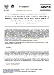
3.3. Cell Layout and Cell-wrapping Technique Figure 1 shows the cell layout employed in our system. We need 19 hexagonal cells having a cell radius. Such cells are determined and information is stored in the 19×2 matrix. For example, base information (5, 1) and base information (5, 2) respectively reveal X and Y coordinate of the fifth base stations. In our system, regulated numbers of users are scattered in each of the 19 cells from which data are taken. Y a x is in t h e s im u la t io n C e ll ( 1 9 th c e ll)
11 12
13
14
X a x is in t h e s im u la t io n
16
5
4
P o s it io n o f b a s e s ta t io n ( 1 9 t h b a s e s ta tio n )
17
6
1
3
18
7
2
10
19
8
9
15
Figure 1. Cell layout In the case of a cellular system using the DCA algorithm, we should take into account not only one sample cell, but also neighboring cells, because co-channel interference from neighboring cells has a significant effect on the performance of the sample cell. For example, the 5th cell is subject to interference from the 1st, 4th, 14th, 15th, 16th, and 6th cells. Cells located farther away, such as the 2nd or 3rd ones, could interfere with the 5th cell. However, it is assumed that such interference is decreased enough by the distance that it can be ignored, and we take into account only the six immediate neighboring cells in the system. On the other hand in the case of the 9th cell, which is located on the boundary of the cell layout, it has only three neighboring cells, the 10th, 2nd, and 8th. Such a “boundary cell” has different performance than an “innerlocated cell,” for example the 9th cell, which would show better performance than the 2nd cells, because fewer cells cause interference in the 9th cell. Consequently, taking user activity in the boundary cells as well as that in an inner cell into account does not adequately evaluate DCA performance [10]. Thus, to avoid such a problem, two solutions can be used. One is to take data only from inner cells such as the 1st, 2nd, 3rd, 4th, 5th, 6th, and 7th cells in Figure 1, and exclude boundary cells. These inner cells are all subject to interference from six neighboring cells and are expected to reveal effective performances of the DCA algorithm. However, because boundary cells do not contribute to output data, we need a larger number of cells to construct the entire cell layout to obtain well-averaged data, making the system burden heavy. The other solution is to use a cellwrapping technique. Figure 2 shows a concept of this technique .In this technique, boundary cells are regarded as neighbors of the boundary cells located almost directly opposite the cell layout. In figure 2, only the 19 shaded cells are cells that really exist, and the other cells are copies of the real cells having the same number. As a result, the 9th cell suffers from interference not only from the 10th, 2nd, 8th cells, but also copies of the 13th, 17th, and 14th cells in the neighboring positions. On this assumption, every cell in the cell layout can be regarded as being “Inner-located cell” having six neighbors.
19
International Journal of Computer Science, Engineering and Information Technology (IJCSEIT), Vol.1, No.2, June 2011
12 18
15
12
16
10
2
4 14
13
2
10 11
7
8
9
3 12
19
8
9
17
6
12
16 15
14
C o p y o f c e ll
17
5
4 13
18
7
3
18
6
1
3
19
8
11
7
O r ig in a l c e ll ( c o lo r e d )
10
19
2
10
11
15 8
9
16
5 14
14
13
17
6
16
5
4
18
Figure 2. Cell-wrapping technique concept To realize cell wrapping, wrap information 19×19 matrixes reveals the relationship among the 19 cells, including cell wrapping. Thus, for example, wrap information (5, :) stores information for fifth cell about other cells, especially wrap information (5, 2) to wrap information (5, 7), which are the numbers of its six neighbors .The concrete usage of this matrix will be explained later.
3.4. Cell Mesh Construction In our system, user distribution is considered to be uniform over one cell as well as over the entire cell layout. Such a condition is realized by cells distributed into a lot of small meshes. A mesh generator in our system, outputs the number of meshes in a cell and stores in a matrix which contains the position of each mesh. Figure 3(a) shows the result, where “Fineness” is a parameter for mesh fineness and is usually set to “Fineness=50” in our system. Here, discrete meshes are used to allocate a certain amount of traffic into the specially shaped area such as a hexagonal cell.
(a) Fineness=50
(b) Fineness=40 Figure 3. Mesh pattern 20
International Journal of Computer Science, Engineering and Information Technology (IJCSEIT), Vol.1, No.2, June 2011
In the system, when, a user initiates a call, we generate a random integer whose value uniformly fluctuates from 1 to mesh number and locates a user on a location in a cell. As a result, each user is scattered in a certain point in a cell with equal probability at its initiation, and we can obtain uniform user distribution over a cell [11].
3.5. Traffic Parameters of a Call Each call generation is subject the Poisson process with its mean arrival rate (calls/hour) for each user. To realize such an arrival rate, we examine each user that is not connected in every time period using a random function. If a value of random function is not more than average arrival rate during every time period, then the user is regarded as having started a call, and the number of generated calls is counted. On the other hand, every initiated call has its own call holding time, and the initiated call is terminated after such a time. The holding time of each call is subject to exponential distribution with a mean value. In our system, we obtained the value of the holding time as the output function, which outputs a random value subject to exponential distribution with an average value of holding time. Figure 4 shows a probability distribution function (pdf) with output of the holding time, which is measured by MATLAB.
Figure 4. Call holding time pdf Moreover, the number of users is also a significant traffic parameter. We can set up the number of user existing in cell and investigate the effects of such fluctuations of the user numbers. In the system results are shown later; we have evaluated the performance of DCA mainly according to such numbers of users per cell.
3.6. Propagation Conditions The strength of the received signal, regardless of the desired wave, or interference wave, is one of the important issues in our system. The transmitted signal suffers from attenuation caused by such factors as distance and obstruction .In the system; we introduce path loss and shadowing as such attenuation factors. We assumed the transmitted signal is subject to path loss with a decay factor of α as in equation (1), in the system. This system provides a function distance (a. b. alpha), where “a” and “b” are a 1×2 matrix and respectively denote coordinates of base station and user position. Then, value of distance (a, b, alpha) reveals the path loss between these two points a and b. Moreover, shadowing is assumed to be subject to log-normal distribution with a standard deviation of “sigma,” corresponding to ξ, in equation (1). We also obtained the value of 21
International Journal of Computer Science, Engineering and Information Technology (IJCSEIT), Vol.1, No.2, June 2011
shadowing subject to log-normal distribution which its standard deviation. Figure 5 shows a pdf of the shadowing attenuation, which is measured by MATLAB.
Figure 5. The pdf of shadowing
3.7. Channel Assignment First of all, uplink power strength from a call-initiating user to the base station is examined. This power is provided by the carrier-to-noise (C/N). Figure 6 shows these conditions, where only path loss is considered. In the system, we first input coordinates of the user’s position and the base station, obtain the path loss value as distance (a, b, alpha), and then add shadowing attenuation to the value. After that we obtain the attenuation value of the desired signal. Using the attenuation value, we can obtain the C/N of the signal received by the base station. After we calculating C/N, we search for an available channel that is not in use, and that satisfies the interference conditions of the C/(N+I). The channel search is conducted in the repeated number channel so that the provided number of channels is examined in its entirety. If another user is allocated the same channel, we calculate the interference from that user.
Figure 6. The path loss conditions We also calculate the attenuation value of the interference signal from this neighboring cell. In this case, there are three additive terms. These three terms play the role of compensating for a 22
International Journal of Computer Science, Engineering and Information Technology (IJCSEIT), Vol.1, No.2, June 2011
miscalculation that could be caused by cell wrapping [11]. We can obtain a suitable calculation of path loss distance (a, b, alpha) including the cell wrapping. We obtain an incorrect value of path loss, we calculate interference from every user that can cause interference and finally add them up as the total interference. Now, as a goal, we have to obtain the C/(N+I) ratio Rcni which can be described as follows: Rcni = =
= From equation (2), we can see that the C/ (N+I) is revealed by using the C/N and C/I. We have already provided the value of the C/N. and the value of the C/I. By using such values, we can calculate the value of the C/ (N+I) ratio in the system. Finally, we examine if the achieved value of the C/ (N+I) can satisfy the interference condition, that is if it is greater than the C/ (N+I) threshold [12]. If the achieved C/ (N+I) exceeds the threshold, a call is accepted, and a channel is allocated to the user. The output is also allocated to the user as its call holding time, which provides the time the call is finished. If the inference condition is no satisfied, we regard such a call as being blocked and the number of blocked calls is counted.
3.8. Channel Check and Reallocation We also check the interference conditions for connected users in every period. This routine is conducted in a similar way to channel assignment, and the C/ (N+I) of allocated channel for each connected user is examined. If the C/(N+I) of the channel is not satisfied, the user releases a currently allocated channel and tries to find an alternative channel in just the same way as channel assignment. At this point, if a channel condition is not satisfied, such event is not regarded as blocking but as the forced termination of a call [13]. Therefore, in that case, the number of forced terminations of calls is counted.
4. FLOWCHART OF THE SYSTEM In figure 7 shows a flowchart of the entire system .Our system consists of three parts: the preparation part, several pieces of information needed for the system are introduced, such as the cell layout or traffic parameters, before the main loop is started. The main loop of our system is activated by the while loop with preliminary finish time. Throughout the entire loop, the status of present users is checked and, if necessary, renewed in a short time interval. Several status indicators are successively stored in a matrix [14]. In every time period in the loop ,each user causes several events, such as call initiation, channel searching, channel allocation, channel reallocation, and call termination based on the status matrix. In a time period, the following events are considered in turns: 1. Calls of connected users terminated if they finish in the period. 2. Calls of still-connected users are examined. If a desirable interference condition is not satisfied, reallocation is attempted by searching for new channels. 3. With preliminary probability, users that are not connected start new calls and search for channels that satisfy the interference condition. 4. Returns to step1. Several types of numerical data are also measured in every period. 23
International Journal of Computer Science, Engineering and Information Technology (IJCSEIT), Vol.1, No.2, June 2011
Figure 7. Flow chart of the system Finally, in the output part, measured and accumulated data in the main loop are organized into output, in the form of output matrix.
5. SIMULATIONS Finally, the entire main loop part is executed; the accumulated data are calculated and stored in the output matrix. We have already counted the essential numerical values such as call number, block number and force termination number, thereby calculating the previously defined blocking probability Pbl and forced termination probability Pfr based on the equations (2) and (3) respectively. In every time period we stored the current value of blocking probability and forced termination probability respectively. Consequently, blocking probability and forced termination probability give transitional data in every time period, so we can determine suitable loop lengths for our system. We can evaluate the results of our system on the consideration of blocking probability and forced termination probability performance according to the number of users. Figure 8 shows the blocking probability versus the number of users and also illustrates the comparison between our proposed system and existing system based on the threshold value (carrier to noise and interference ratio). We have considered 10 as threshold value in our system and the previous task has been taken the value 12 as threshold, evaluated the better performance of the blocking probability in the proposed system than the existing system. So this system provides the low blocking probability and initiates large number of calls in dynamic channel allocation environment.
24
International Journal of Computer Science, Engineering and Information Technology (IJCSEIT), Vol.1, No.2, June 2011
Figure 8. Blocking probability versus the number of users. Figure 9 shows the comparison between our proposed system and existing system based on the threshold value (carrier to noise and interference ratio). We have considered 10 as threshold value in our system and the existing task has been taken the value 12 as threshold. As our proposed system generated the large number of calls than the existing system, forced termination probability of this system has been increased significantly.
Figure 9. Forced termination probability versus the number of users. 25
International Journal of Computer Science, Engineering and Information Technology (IJCSEIT), Vol.1, No.2, June 2011
In our system, blocking probability decreases but forced termination increases significantly. The message complexity increases because of using a large number (19) of cells.
6. CONCLUSIONS In cellular mobile communication system channel demand has both spatial and temporal variation. It is seen that during busy office hours (temporal) or in some part of the city (spatial) the channel allocation changes very frequently and rapidly. Thus an efficient channel allocation algorithm is very complex and complicated task. Dynamically changing the channels allocated to different cells enable the system to adapt to temporal and spatial distribution of channel demand. The proposed technique which is based on dynamic channel allocation will show remarkable achievement in terms of i) blocking probability ii) forced termination probability. We shall improve the technique in future that will outperform the existing technique both during peak hours and in congested part of the city, reducing the message complexity and channel acquisition delay. As the technology advances mobile computing has gained lot of importance in recent years. Mobile Computing uses cellular/wireless communication network. Dynamic channel allocation has received more attention because of high reliability and scalability. Most of the allocation techniques did not make full use of the available channels. The proposed channel allocation technique makes efficient reuse of channels using cell-layout and cell-wrapping. The simulations results have been showed the blocking rate and forced termination rate of the proposed technique that are significantly less than the previous techniques.
REFERENCES [1]
Theodore S. Rappaport. Wireless communications principles and practice, Second edition 2003.
[2]
Shengming Jiang, Xinhua Ling and Kee-Chaing Chua, Performance of Channel Carrying for Handoff in a DCA Cellular Network, Wireless Personal Communications Journal, Vol 25, Number 3 / June, 2003.
[3]
Scott Jorden. Resourse allocation in wireless networks. Journal of high speed networks, 5(1): 2334, 1996.
[4]
I.Katzela et.al. Channel assignment schemes for cellular mobile telecommunications systems. IEEE personal communication 10-31, 1996.
[5]
Justin C.I. et.al. Performances issues and algorithms for dynamic channel assignment. IEEE journal on selected areas in communications 11(6): 955-963, 1993.
[6]
Jianchang Yang et.al. A fault-tolerant channel allocation algorithm for cellular network with mobile base stations. IEEE transactions on vehicular technology 56(1): 349-361, 2007.
[7]
Guhong Cao et.al. Distributed fault-tolerant channel allocation for cellular networks. IEEE journal on selected areas in communications, 18(7): 1326-1337, 2000.
[8]
I. Katzela and M. Naghshineh, “Channel assignment schemes for cellular mobile telecommunication systems: A comprehensive survey,” IEEE Personal Comms., pp.10-31, June 1999.
[9]
Angel Lozano, and Donald C. Cox, “Distributed Dynamic Channel Assignment in TDMA Mobile Communication Systems,” IEEE Transactions on Vehicular Technology, VOL. 51, NO. 6, November 2002.
[10]
Megha Gupta and A.K. Sacham.” Distributed Dynamic Channel Allocation Algorithm for Cellular Mobile Network” Journal of Theoretical and Applied Information Technology” 2007.
[11]
L. B. Eliane, “A Distributed Channel Allocation Schemes for Cellular Networks using Intelligent Software Agents.” November 2000. 26
International Journal of Computer Science, Engineering and Information Technology (IJCSEIT), Vol.1, No.2, June 2011
[12]
P. Ravi, “Distributed Wireless Channel Allocation in Cellular Systems with Mobile Base Stations”, Workshop on Nomadic being held in conjunction with IPPS, April 5,1997
[13]
Kendall Graham and Mohamad Mazlan, “Channel Assignment in cellular Communication using A Great Deluge Hyper-Heuristics, Automated Scheduling, Optimisation and Planning (ASAP)”, Research Group, University of Nottingham, School of Computer Science and IT Nottingham NG8 1BB, UK
[14]
P. Cherriman, F. Romiti and L. Hanzo, “Channel Allocation for Third-generation Mobile Radio Systems” , Rhodes, Greece, volume 1, pp. 255-261, ACTS'98, 8-11th June 1998.
Biography Md. Sadek Ali received the Bachelor’s and Master‘s Degree in the Department of Information and Communication Engineering (ICE) from Islamic University, Kushtia, in 2004 and 2005 respectively. He is currently a Lecturer in the department of ICE, Islamic University, Kushtia-Bangladesh. Since 2003, he has been working as a Research Scientist at the Communication Research Laboratory, Department of ICE, Islamic University, Kushtia, where he belongs to the spread-spectrum research group. He has four published paper in international and two national journals in the same areas. His areas of interest include Wireless Communications, optical fiber communication, Spread Spectrum and mobile communication.
M. A. Masud received the Bachelor’s and Master‘s Degree in Information & Communication Engineering from Islamic University, Kushtia, Bangladesh in 2003, and 2004 respectively. He is currently Assistant Professor in the department of CSIT, Patuakhali Science and Technology University, Patuakhali, Bangladesh. He has five published papers in international and national journals. His areas of interest include signal processing & mobile communication.
Md. Shariful Islam received the Bachelor’s and Master‘s Degree in Applied Physics, Electronics & Communication Engineering from Islamic University, Kushtia, Bangladesh in 1999, and 2000 respectively. He is currently Assistant Professor in the department of ICE, Islamic University, Kushtia-7003 Bangladesh. He has five published papers in international and national journals. His areas of interest include signal processing & mobile communication.
Md. Alamgir Hossain received the Bachelor’s and Master‘s Degree in the Dept. of Information and Communication Engineering (ICE) from Islamic University, Kushtia, in 2003 and 2004, respectively. He is currently Lecturer in the department of ICE, Islamic University, Kushtia-7003, and Bangladesh. He was a lecturer in the Dept. of Computer Science & Engineering from Institute of Science Trade & Technology (Under National University), Dhaka, Bangladesh from 23th October, 2007 to 18th April 2010. Since 2003, he has been working as a Research Scientist at the Communication Research Laboratory, Department of ICE, Islamic University, Kushtia, where he belongs to the spread-spectrum research group. His current research interests include Wireless Communications, Spread Spectrum and mobile communication, Signal processing, Data Ming.
27