Posición tipo Saturados para Robot Manipuladores. In Congreso Nacional de. Electrónica, Centro de Convenciones William o Jenkins. Puebla. México, 2002.
26 Performance Evaluation of Fault-Tolerant Controllers in Robotic Manipulators Claudio Urrea1, John Kern1,2 and Holman Ortiz2 1Departamento
de Ingeniería Eléctrica, DIE, Universidad de Santiago de Chile, USACH, Santiago 2Escuela de Ingeniería Electrónica y Computación, Universidad Iberoamericana de Ciencias y Tecnología, UNICIT, Santiago Chile 1. Introduction Thanks to the incorporation of robotic systems, the development of industrial processes has generated a great increase in productivity, yield and product quality. Nevertheless, as far as technological advancement permits a greater automation level, system complexity also increases, with greater number of components, therefore rising the probability of failures or anomalous operation. This can result in operator's hazard, difficulties for users, economic losses, etc. Robotic automatic systems, even if helped in minimizing human operation in control and manual intervention tasks, haven't freed them from failure occurrences. Although such failures can´t be eliminated, they can be properly managed through an adequate control system, allowing to reduce degraded performance in industrial processes.
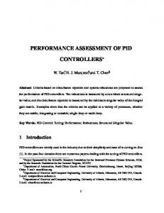
Fig. 1. Performance regions under failure occurrence In figure 1 we see a scheme showing the different performance regions a given system can adopt when a failure occurs. If the system deviates to a degraded performance region in, presence of a failure, it can recover itself moving into an optimum performance region, or
554
Robotic Systems – Applications, Control and Programming
near to it. These systems are called fault tolerant systems and have become increasingly important for robot manipulators, especially those performing tasks in remote or hazardous environments, like outer space, underwater or nuclear environments. In this chapter we will address the concept of fault tolerance applied to a robotic manipulator. We will consider the first three degrees of freedom of a redundant SCARAtype robot, which is intended to follow a Cartesian test trajectory composed by a combination of linear segments. We developed three fault-tolerant controllers by using classic control laws: hyperbolic sine-cosine, calculated torque and adaptive inertia. The essays for such controllers will be run in a simulation environment developed through MatLab/Simulink software. As a performance requirement for those controllers, we considered the application of a failure consisting in blocking one of the manipulator's actuators during trajectory execution. Finally, we present a performance evaluation for each one of the above mentioned fault-tolerant controllers, through joint and Cartesian errors, by means of graphics and rms rates.
2. Fault tolerant control The concept of fault tolerant control (Zhang & Jiang, 2003) comes first from airplane fault tolerant control; although at scientific level it appears later, as a basic aim in the first congress of IFAC SAFEPROCESS 1991, with an especially stronger development since the beginning of 21th century. Fault tolerant control can be considered both under an active or passive approach, as seen in figure 2a. Passive tolerant control is based on the ability of feedback systems to compensate perturbations, changes in system dynamics and even system failures (Puig, Quevedo, Escobet, Morcego, & C., 2004). Passive tolerant control considers a robust design of the feedback control system in order to immunize it from some specific failures (Patton, 1997). Active tolerant control is centered in on-line failure, that is, the ability to identify the failing component, determine the kind of damage, its magnitude and moment of appearance and, from this information, to activate some mechanism for
Fig. 2a. Types of fault tolerant control
Performance Evaluation of Fault-Tolerant Controllers in Robotic Manipulators
555
rearrangement or control reconfiguration, even stopping the whole system, depending on the severity of the problem (Puig, Quevedo, Escobet, Morcego, & C., 2004). Fault tolerant control systems (being of hybrid nature) consider the application of a series of techniques like: component and structure analysis; detection, isolation and quantification of failures; physical or virtual redundancy of sensors and/or actuators; integrated real-time supervision of all tasks performed by the fault tolerant control, as we can see in figure 2b (Blanke, Kinnaert, Lunze, & Staroswiecki, 2000).
Fig. 2b. Stages included in the design of a fault tolerant control system
556
Robotic Systems – Applications, Control and Programming
In the evaluation of fault tolerant controllers it is assumed that a robotic manipulator where a failure has arisen in one or more actuators, can be considered as an underactuated system, that is, a system with less actuators than the number of joints (El-Salam, El-Haweet, & and Pertew, 2005). Those underactuated systems present a greater degree of complexity compared with the simplicity of conventional robot control, being not so profoundly studied yet (Rubí, 2002). The advantages of underactuated systems have been recognized mainly because they are lighter and cheaper, with less energy consumption. Therefore, a great deal of concern is being focused on those underactuated robots (Xiujuan & Zhen, 2007). In figure 3 it is shown a diagram displaying the first three degrees of freedom of a SCARA type redundant manipulator, upon which essays will be conducted considering a failure in the second actuator, making the robot become an underactuated system.
3. SCARA-type redundant manipulator For the evaluation of fault-tolerant controllers, we consider the first three degrees of freedom of a redundant SCARA-type robotic manipulator, with a failure occurring in one of its actuators; such a system can be considered as an underactuated system, i.e., with less actuators than the number of joints (Xiujuan & Zhen, 2007). Those underactuated systems have a greater complexity compared with the simplicity of conventional robots control, and they haven't been so deeply studied yet (Rubí, 2002). The advantages of underactuated systems have been remarked mainly because they are lighter and less expensive; also having less energy consumption, consequently an increasing level of attention is being paid to underactuated robots (Xiujuan & Zhen, 2007). In figure 3 it is shown the scheme of a redundant SCARA-type robotic manipulator, and in figure 4 we can see a diagram showing the first three degrees of freedom of such manipulator, on which the essays will be carried on.
Fig. 3. Scheme of a SCARA-type redundant manipulator
Performance Evaluation of Fault-Tolerant Controllers in Robotic Manipulators
557
The considered failure is the blocking of the second actuator, what makes this robot an underactuated system. Having in mind the exposed manipulator, it is necessary to obtain its model; therefore we will consider that the dynamic model of a manipulator with n joints can be expressed through equation (1):
+C ( q , q ) +G( q ) + F ( q ) τ = M( q ) q
(1)
where: τ : Vector of generalized forces (n×1 dimension). M: Inertia matrix (n×n dimension). C : Centrifugal and Coriolis forces vector (n×1dimension). q : Components of joint position vector. : Components of joint speed vector. G : Gravity force vector (n×1dimension). : Joint acceleration vector (n×1dimension). F : Friction forces vector (n×1dimension). Under failure conditions in actuator number 2, that is, it’s blocking, the component 2 of equation (1) becomes a constant.
Fig. 4. Scheme of the three first DOF of a redundant SCARA-type robotic manipulator
4. Considered controllers Considering the hybrid nature of fault tolerant control, it is proposed an active fault tolerant control having a different control law according to the status of the robotic manipulator, i.e.
558
Robotic Systems – Applications, Control and Programming
normal or failing, with on-line sensing of possible failures and, in correspondence with this, reconfiguring the controller by selecting the most adequate control law (changing inputs and outputs). Next, we will present a summary of the controllers considered for performance evaluation when a failure occurs in the second actuator of the previously described manipulator.
5. Fault tolerant controller: hyperbolic sine and cosine This controller is based on the classic controller hyperbolic sine-cosine presented in (Barahona, Espinosa, & L., 2002), composed by a proportional part based on sine and hyperbolic cosine functions, a derivative part based on hyperbolic sine and gravity compensation, as shown in equation (2). The proposed fault tolerant control law includes two classic hyperbolic sinecosine controllers that are "switched" to reconfigure the fault tolerant controller.
τ = Kpsinh ( qe ) cosh ( qe ) - Kvsinh ( q ) +G( q )
(2)
qe = qd - q
(3)
According to equations (2) and (3): Kp : Proportional gain, diagonal definite positivematrix (n×n dimension). Kv : Derivative gain, diagonal definite positive matrix (n×n dimension). qe : Joint position error vector (n×1dimension). qd : Desired joint position vector (n×1dimension). In (Barahona, Espinosa, & L., 2002) it is established that robotic manipulator's joint position error will tend asymptotically to zero as long as time approaches to infinite:
lim qe → 0
(4)
t→∞
This behavior is proved analyzing equation (5) and pointing that the only equilibrium point for the system is the origin (0,0). d q e a1 = dt q a2 a1 = -q a2 = M ( q )
-1
(5)
( K sinh ( q ) cosh ( q ) -K sinh ( q ) - C ( q,q ) q ) p
e
e
v
6. Fault tolerant controller: Computed torque Another active fault tolerant controller analyzed here uses a control law by computed torque, consisting in the application of a torque in order to compensate the centrifugal, Coriolis, gravity and friction effects, as shown in equation (6).
(
)
ˆ ( q , q ) + G ˆ ( q ) + Fˆ ( q ) ˆ (q) q d + K vq e + K pqe +C τ=M where: ˆ : Estimation of inertia matrix (n×n dimension). M
(6)
Performance Evaluation of Fault-Tolerant Controllers in Robotic Manipulators
ˆ : C ˆ : G ˆF :
Estimation of centrifugal and Coriolis forces vector (n×1dimension). Estimation of gravity force vector (n×1dimension). Estimation of friction forces vector (n×1dimension). K v 1 Kv =
Kv :
K v2
K v n
(7)
Diagonal definite positive matrix (n×n dimension). K p 1 Kp =
Kp : d : q
559
K p2
K p n
(8)
Diagonal definite positive matrix (n×n dimension). Desired joint acceleration vector (n×1 dimension).
q e = q d - q
(9)
q e : Joint speed error vector (n×1dimension). If estimation errors are little, joint errors near to a linear equation, as shown in equation (10). e + K vq e + Kpqe ≈ 0 q
(10)
7. Fault tolerant controller: Adaptive inertia The fault tolerant control under examination is based on an adaptive control law, namely: adaptive inertia (Lewis, Dawson, & Abdallah, 2004), (Siciliano & Khatib, 2008), for what it is necessary to consider the manipulator dynamic model in the form expressed in equation (11). The term corresponding to centrifugal and Coriolis forces is expressed through a matrix Vm.
+ Vm ( q , q ) q +G ( q ) + F ( q ) τ = M(q ) q
(11)
In this case, we define an auxiliary error signal r and its derivative , as shown in equations (12) and (13), respectively:
r = Λqe + q e
(12)
e r = Λq e + q
(13)
where: Λ : Diagonal definite positive matrix (n×n dimension).
560
Robotic Systems – Applications, Control and Programming
λ1 Λ=
λ2
λn
(14)
When replacing equations (3), (9), (12) and (13) into expression (11), we obtain:
d + Λq e ) +Vm ( q , q ) ( q d + Λqe ) +G ( q ) +F ( q ) - M ( q ) r - Vm ( q , q ) r τ = M( q ) (q
(15)
And making the following matching:
d + Λq e ) +Vm ( q , q ) ( q d + Λqe ) +G ( q ) + F ( q ) Y ( ) φ = M ( q)( q
(16)
where: Y11 Y12 Y21 Y22 qd ) = Y ( q , q , q d , q d , Y n 1 Yn 2
Y1 n Y2 n Ynn
(17)
Y ( ) : Regression matrix (n×n dimension). φ : Parameter vector (n×1 dimension). With these relationships, expression (15) can be rewritten in the following way: τ = Y ( ) φ - M ( q ) r - Vm ( q , q ) r Y ( )
(18)
And the control torque is expressed through equation (19):
ˆ + Kvr τ = Y ( ) φ
(19)
where: ˆ : Parameter estimation vector (n×1dimension). φ Kv: Diagonal definite positive matrix (n×n dimension). The adaptive control updating rule can be expressed by:
ˆ = − φ = Γ YT ( ⋅) r φ
(20)
where: Γ: Diagonal definite positive matrix (n×n dimension).
8. Fault tolerant control simulator The three above mentioned control laws, along with the dynamic model of the redundant SCARA-type manipulator considering the first three degrees of freedom (Addendum A), are run under the simulation structure shown in figure 5, where we can see the hybrid nature of this kind of controller.
Performance Evaluation of Fault-Tolerant Controllers in Robotic Manipulators
561
In Addendum B we show the set of parameter values employed in the manipulator dynamic model, and the gains considered for each kind of fault tolerant controller.
Fig. 5. Block diagram of the structure of the fault tolerant controller used to test the above mentioned control laws
9. Results After establishing the control laws being utilized, we determine the trajectory to be entered in the control system to carry out the corresponding performance tests of fault tolerant control algorithms. This trajectory is displayed in figure 6.
562
Robotic Systems – Applications, Control and Programming
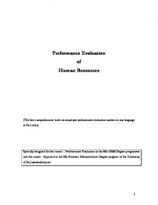
Fig. 6. Cartesian test trajectory Figures 7 and 8a show the curves corresponding to the differences between desired and real joint trajectories, and between desired and real Cartesian trajectories, respectively, all this under hyperbolic sine-cosine fault tolerant control when there is a failure in actuator 2 at 0.5 sec from initiating movement. Where: Joint trajectory error, joint 1. eq1 : Joint trajectory error, joint 2. eq2 : eq3 : Joint trajectory error, joint 3. Cartesian trajectory error, x axis. ex : ey : Cartesian trajectory error, y axis.
Fig. 7. Joint trajectory error with fault control using hyperbolic sine-cosine controller
563
Performance Evaluation of Fault-Tolerant Controllers in Robotic Manipulators
Fig. 8a. Cartesian trajectory error with fault control using hyperbolic sine-cosine controller The performance of fault tolerant controller by computed torque is shown in figures 8b and 9, displaying the curves for joint and Cartesian errors under the same failure conditions than the previous case.
Joint trajectory error with fault control
10 8 6
eq ( ° )
4 2 0 -2 -4
eq1
-6
eq2 eq3
-8 -10
0
0.5
1
1.5
2 2.5 Time (sec)
3
3.5
Fig. 8b. Joint trajectory error with fault control using computed torque controller
4
564
Robotic Systems – Applications, Control and Programming
Fig. 9. Cartesian trajectory error with fault control using computed torque controller In figures 10 and 11 we can see charts displaying respectively joint and Cartesian errors corresponding to the performance of fault tolerant controller by adaptive inertia, under the same failure conditions imposed to the previous controllers.
Joint trajectory error with fault control
10 8 6 4 2 0 -2 -4
eq1
-6
eq2 eq3
-8 -10
0
0.5
1
1.5
2 2.5 Time (sec)
3
3.5
Fig. 10. Joint trajectory error with fault control using adaptive inertia controller
4
565
Performance Evaluation of Fault-Tolerant Controllers in Robotic Manipulators
Fig. 11. Cartesian trajectory error with fault control using adaptive inertia controller
Joint error rms ( ° )
Joint performance index 3,00
eq1
2,50
eq2 eq3
2,00 1,50 1,00 0,50 0,00
sinh-cosh
calculated torque Controller type
Fig. 12. Performance index corresponding to joint trajectory
adaptive inertia
Cartesian error rms (m)
566
Robotic Systems – Applications, Control and Programming
Cartesian performance index 0,015
ex ey
0,01 0,005 0
sinh-cosh
calculated torque
adaptive inertia
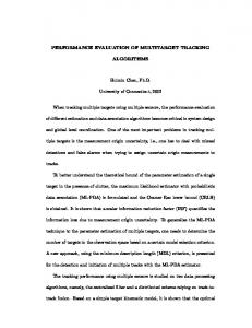
Controller type Fig. 13. Performance index corresponding to Cartesian trajectory Finally, in figures 12 and 13 it is shown a performance summarization of the analyzed fault tolerant controllers in terms of joint and Cartesian mean square root errors, accordingly to equation (21) rms =
1 n
n
e i =1
i
2
(21)
Where ei represents articular trajectory as well as Cartesian errors.
10. Conclusions In this work we presented a performance evaluation of three fault tolerant controllers based on classic control techniques: hyperbolic sine-cosine, calculated torque and adaptive inertia. Those fault tolerant controllers were applied on the first three degrees of freedom of a redundant SCARA-type robotic manipulator. The different system stages were implemented in a simulator developed using MatLab/Simulink software, allowing to represent the robotic manipulator behavior following a desired trajectory, when blocking of one of its actuators occurs. In this way we obtained the corresponding simulation curves. From the obtained results, we observed that the adaptive inertia fault tolerant controller have errors with less severe maximums than the other controllers, resulting in more homogeneous manipulator movements. We noticed that greater errors were produced with the calculated torque fault tolerant controller, both for maximums and rms. Consequently, the best performance is obtained when using the adaptive inertia controller, as shown in figures 14 and 15. It is also remarkable that the hyperbolic sine-cosine fault tolerant controller have a lesser implementation complexity, since it does not require the second derivative of joint position. This can be a decisive factor in the case of not having high performance processors.
Performance Evaluation of Fault-Tolerant Controllers in Robotic Manipulators
567
11. Further developments Thanks to the development of this work, from the implemented simulation tools and the obtained results, fault tolerant control systems essays are being currently carried out, in order to apply them to actual robotic systems, with and without link redundancy, like the SCARA-type robots shown in figure 14 and figure 15, respectively.
Fig. 14. SCARA-type redundant robot, DIE-USACH
Fig. 15. SCARA-type robot, DIE-USACH
12. Addendum A: Manipulator's dynamic model The manipulator's dynamic model is given by equations a1 to a14.
M11 M = M21 M31
M12 M22 M32
M13 M23 M33
(a1)
568
Robotic Systems – Applications, Control and Programming
(
)
2 2 M11 = I 1zz + I 2zz + I 3zz + m1lc1 + m2 l12 + lc2 + m2 2l1lc2 cosθ 2 + ...
(
m3 l + l + l + 2 l1l2 cosθ 2 + 2l2 lc3 cosθ 3 + 2 l1lc3 cos (θ 2 +θ 3 ) 2 1
2 2
2 c3
(
)
)
2 M21 = M12 = I 2zz + I 3zz + m2 lc2 + l1lc2 cosθ 2 + ...
(
m3 l + l + l1l2 cosθ 2 + 2 l2 lc3 cosθ 3 + l1lc3 cos (θ 2 + θ 3 ) 2 2
2 c3
(
)
)
2 M31 = M13 = I 3zz + m3 lc3 + l2 lc3 cosθ3 + m3l1lc3 cos (θ 2 + θ 3 )
(
2 2 M22 = I 2zz + I 3zz + m2 lc2 + m3 l22 + lc3 + 2l2 lc3 cosθ 3
(
2 M32 = M23 = I 3zz + m3 lc3 + l2 lc3 cosθ 3
(a2)
(a3)
(a4)
)
(a5)
)
(a6)
M33 = I 3zz + m3lc32
(a7)
C = [C 11 C 21 C 31 ]
T
(a8)
C 11 = −2 l1 ( m2 lc2 sinθ 2 + m3l2 sinθ 2 )θ1θ2 − 2 l1 m3lc3 sin (θ 2 + θ 3 )θ1θ2 + ... − m l l sinθ ⋅θ 2 + m ( l l sinθ + l l sin (θ + θ ) )θ 2 + ... 2 1 c2
2
2
3
1 2
2
1 c3
2
3
2
− 2 lc3m3 ( l2 sinθ 3 + l1 sin (θ 2 + θ 3 ) )θ1θ3 + ...
(a9)
− 2 m3lc3 ( l2 sinθ 3 + l1 sin (θ 2 + θ 3 ) )θ2θ3 + ... m3 ( −l2 lc3 sinθ 3 − l1lc3 sin (θ 2 + θ 3 ) )θ32
C 21 = m3 ( l1l2 sin θ 2 + l1lc3 sin (θ 2 + θ 3 ) )θ12 + m2 l1lc2 sin θ 2 ⋅θ12 + ... −2 m l l sin θ ⋅θ θ − 2 m l l sin θ ⋅θ θ − m l l sin θ ⋅θ 2
(a10)
C 31 = m3 ( l2 lc3 sin θ 3 + l1lc3 sin (θ 2 + θ 3 ) )θ12 + ... 2m l l sin θ ⋅θ θ + m l l sin θ ⋅θ 2
(a11)
C 31 = m3 ( l2 lc3 sin θ 3 + l1lc3 sin (θ 2 + θ 3 ) )θ12 + 2m3l2 lc3 sin θ 3 ⋅θ1θ2 + ... m l l sin θ ⋅θ 2
(a12)
G = [ 0 0 0]
(a13)
3 2 c3
3
1 3
3 2 c3
3 2 c3
3
3 2 c3
3
1 2
3
2 3
3 2 c3
3
3
3
2
2
T
F = [ F11 F21 F31 ]
T
where: m1 : First link mass. m2 : Second link mass.
3 2 c3
(a14)
569
Performance Evaluation of Fault-Tolerant Controllers in Robotic Manipulators
m3 l1 l2 l3 lc1 lc2 lc3 I1zz I2zz I3zz
: : : : : : : : : :
Third link mass. First link length. Second link length. Third link length. Length from 1st link origin to its centroid. Length from 2nd link origin to its centroid. Length from 3rd link origin to its centroid. 1st link inertial momentum with respect to the first z axis of its joint. 2nd link inertial momentum with respect to the first z axis of its joint. 3rd link inertial momentum with respect to the first z axis of its joint.
13. Addendum B: Considered parameter values Parameter values considered for the manipulator as well as controller gains values are shown in tables B1 and B2, respectively. Link 1
Link 2
Link 3
Units
l1
= 0.2
l2
= 0.2
l3
= 0.2
lc1
= 0.0229
lc2
= 0.0229
lc3
= 0.0983
m1
= 2.0458
m2
= 2.0458
m3
= 6.5225
[m] [m] [kg ]
I1zz
= 0.0116
I2zz
= 0.0116
I3zz
= 0.1213
kg ⋅m 2
Fv1
= 0.025
Fv2
= 0.025
Fv3
= 0.025
N⋅m ⋅s rad
Feca1 = 0.05
Feca2 = 0.05
Feca3 = 0.05
Fecb1 = -0.05
Fecb2 = -0.05
Fecb3 = -0.05
[ N ⋅ m] [ N ⋅ m]
Table B1. Considered parameters for the manipulator
Controller Type
Kv1, Kv2, Kv3
3, 2, 1
λ1, λ2, λ3
__
Computed Torque 800, 800, 800 140, 140, 140 __
γ1, γ2, γ3
__
__
Constants Kp1, Kp2, Kp3
Table B2. Controller gains
Hyperbolic Sine-Cosine 400, 300, 200
Adaptive Inertia __
0.1, 0.1, 0.1
20, 20, 20 8, 8, 8
570
Robotic Systems – Applications, Control and Programming
14. References Barahona, J., Espinosa & L., C.F., 2002. Evaluación Experimental de Controladores de Posición tipo Saturados para Robot Manipuladores. In Congreso Nacional de Electrónica, Centro de Convenciones William o Jenkins. Puebla. México, 2002. Blanke, M., Kinnaert, M., Lunze, J. & Staroswiecki, M., 2000. What is Fault-Tolerant Control. In IFAC Symposium on Fault Detection, Supervision and Safety for Technical Process SAFEPROCESS 2000. Budapest, 2000. Springer-Verlag Berlin Heidelberg. El-Salam, A., El-Haweet, W. & and Pertew, A., 2005. Fault Tolerant Kinematic Controller Design for Underactuated Robot Manipulators. In The Automatic Control and Systems Engineering Conference. Cairo, 2005. Lewis, F., Dawson, D. & Abdallah, C., 2004. Robot Manipulator Control Theory and Practice. New York: Marcel Dekker, Inc. Patton, R.J., 1997. Fault-Tolerant Control: The 1997 Situation. In Proc. IFAC Symposium Safeprocess. Kingston Upon Hull, 1997. Puig, V. et al., 2004. Control Tolerante a Fallos (Parte I): Fundamentos y Diagnóstico de Fallos. Revista Iberoamericana de Automática e Informática Industrial, 1(1), pp.15-31. Rubí, J., 2002. Cinemática, Dinámica y Control de Robots Redundantes y Robots Subactuados. Tesis Doctoral. San Sebastián, España: Universidad de Navarra. Siciliano, B. & Khatib, O., 2008. Handbook of Robotics. Berlin, Heidelberg: Springer-Verlag. Xiujuan, D. & Zhen, L., 2007. Underactuated Robot Dynamic Modeling and Control Based on Embedding Model. In 12th IFToMM World Congress. Besançon. France, 2007. Zhang, Y. & Jiang, J., 2003. Bibliographical Review on Reconfigurable Fault-Tolerant Control Systems. In Proceedings IFAC SAFEPROCESS. Washington, D.C., USA, 2003.