Key-Words: Hybrid systems, piecewise affine systems, approximation of nonlinear systems ... the drum water level (in) and y4 is the steam flow rate. (kg/s); x1 is ...
Proceedings of the 8th WSEAS International Conference on SYSTEM SCIENCE and SIMULATION in ENGINEERING
Piecewise affine approximation of nonlinear systems – a case study of a benchmark nonlinear boiler RADEK HORÁLEK* AND JAROSLAV HLAVA ** *Institute of Systems Control and Reliability Management **Institute of Mechatronics and Computer Engineering Technical University of Liberec, Faculty of Mechatronics 416 17 Liberec, Studentská 2 CZECH REPUBLIC {radek.horalek, jaroslav.hlava}@tul.cz Abstract: This paper deals with piecewise affine (PWA) approximation of nonlinear systems. Its motivation is simple. If the controlled plant exhibits nonlinear behavior, linear controller based on linearized model may often be unable to achieve satisfactory performance. On the other hand, intrinsic complexity of the nonlinear controller based on full nonlinear model may prevent it from practical application. PWA model that uses a set of switched partial linear models can then represent the middle way between simplifications of the linearized model and complexity of the nonlinear model. The paper uses a case study of a nonlinear power plant boiler. It shows that its complex nonlinear dynamical behavior can well be approximated with a relatively simple PWA system. Unlike one linearized model, this PWA approximation fits boiler dynamic behavior very well. As the development of model predictive control of the PWA systems has already reached a substantial level of maturity, this PWA model can be used as a basis for the design of hybrid model predictive control for this boiler. Key-Words: Hybrid systems, piecewise affine systems, approximation of nonlinear systems
1 Introduction A strong emphasis on energy efficient production and tight emission control is now imperative in all branches of industry. This fact has an important impact also on the field of automatic control. Traditional control systems based on linear control theory are no more able to achieve the level of control performance that is dictated by the contemporary requirements. Since the behavior of almost all technical systems is nonlinear, nonlinear control methods can be expected to be a more promising approach. However, the practical application of nonlinear control methods is fairly involved and as a result of it, the number of reported successful applications of nonlinear control is limited. This fact is particularly well documented in the case of the model predictive control (MPC), which is the most widely applied advanced control method. Although the comprehensive survey of MPC applications given by Quin and Badgwell [6] reports some successful applications of the non-linear MPC, the vast majority of practical MPC applications are based on linear models. Consequently their achievable performance is limited. A potentially interesting alternative to simplistic linear control and exceedingly complex
ISSN: 1790-2769
nonlinear control is the hybrid model predictive control based on piecewise affine (PWA) models. It was stated already by Sonntag in its seminal paper [7] that more general nonlinear systems can be globally approximated arbitrarily closely by PWA systems. At the same time PWA systems are very similar to linear systems. In fact the only difference between linear and affine systems is the presence of a constant term in state equations. Given the scope of this conference mainly on system theory and simulation, this paper will be not so much concerned with the control itself but it will mainly focus on the ability of PWA modeling formalism to describe complex nonlinear behavior and in this way to serve as a suitable basis for the controller design. The paper will use a case study of a power plant boiler that was given in [5] as a benchmark for nonlinear controller design. This boiler is considerably nonlinear and its approximation with a single linear model is clearly not satisfactory. However, it will be shown that its dynamics can adequately be described with a PWA model. This model can then subsequently be used as a basis for hybrid model predictive controller design.
273
ISBN: 978-960-474-131-1
Proceedings of the 8th WSEAS International Conference on SYSTEM SCIENCE and SIMULATION in ENGINEERING
y3 (t ) = c70 x1 (t − τ 6 ) + c71 x3 (t − τ 6 )
2 Nonlinear boiler model
+ c72 x 4 (t − τ 6 )x1 (t − τ 6 ) + c73u 3 (t − τ 3 − τ 6 )
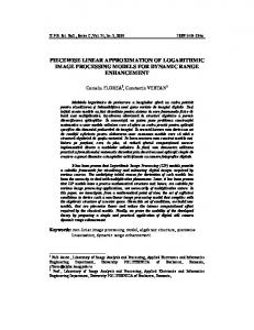
The boiler considered is of the drum boiler type. Its structure as described in [5] is shown in Fig.1. The main control objectives associated with the boiler control are the following. Steam pressure must be maintained on the desired value despite load variations. At the same time the desired level of water in the drum must also be kept at desired value. The fuel/air ratio in the combustion chamber must respect safety, efficiency and ecological requirements.
+ c74 u1 (t − τ 1 − τ 6 ) + c79
[c75 x1 (t − τ 6 ) + c76 ][1 − c77 x3 (t − τ 6 )] x3 (t − τ 6 )[x1 (t − τ 6 ) + c78 ] y4 (t ) = [c81x4 (t −τ 7 ) + c82 ]x1 (t −τ 7 )
(7)
+
(8) The numerical values of the coefficients of this model are given in Table 1. Table 1: Coefficients of the nonlinear model
c11 = −0.00478
c70 = −0.1048569
c12 = 0.280
c71 = 0.15479
c13 = 0.01348
c72 = 0.4954961
c12 = 0.280
c73 = −0.20797
c21 = 0.1540357 c74 = 1.2720 c22 = 103.5462
c75 = −324212.7805
c23 = 107.4835
c76 = −99556.24778
c24 = 1.95150
c77 = 0.0011850
c25 = 29.04
c78 = −1704.50476
c26 = 1.824
c79 = −103.7351
c31 = 0.00533176 c81 = 0.85668
Fig. 1 Schematic structure of the drum boiler [5].
c32 = 0.0251950 c82 = −0.18128
The nonlinear control oriented boiler model published in [5] in explicit form is given by equations (1-8), where y1 is the measured drum pressure (psi), y2 is measured oxygen level (%), y3 is the drum water level (in) and y4 is the steam flow rate (kg/s); x1 is the drum pressure state (kg/cm2), x2 is the excess oxygen level state (%), x3 is the system fluid density (kg/m3) and x4 is the exogenous variable related to the load disturbance intensity. Manipulated variables u1, u2, u3 are the fuel flow rate, the air flow rate and the feed water flow rate with normalized values between (0-1). x&1 (t ) = c11 x4 (t )x19 / 8 (t ) + c12 u1 (t − τ 1 ) − (1) − c13u 3 (t − τ 3 ) + c14 x& 2 (t ) = −c21 x 2 (t ) + c u (t − τ 2 ) − c23u1 (t − τ 1 ) − c24 u1 (t − τ 1 )x 2 (t ) (2) + 22 2 c25u 2 (t − τ 2 ) + c 26 u1 (t − τ 1 ) (3) x& 3 (t ) = c31 x1 (t ) − c32 x 4 (t )x1 (t ) + c3u 3 (t − τ 3 ) x&4 (t ) = −c41x4 (t ) + c42u1 (t −τ 1 ) + c43 (4) y1 (t ) = c51x1 (t − τ 4 ) (5) y2 (t ) = c61x2 (t − τ 5 ) (6)
c33 = 0.7317058 τ 1 = 2 c41 = 0.04 c42 = 0.029988 c43 = 0.018088 c51 = 14.214 c61 = 1.00
For the comparison between linearized and nonlinear model, the linearized model around the nominal operating point (9) recommended in [5] was computed. The resulting matrices are given by (10-14). The simulation results in Figs 2-5 confirm that significant differences between the responses of the nonlinear and the linear model arise if the plant operating point is not close to the nominal operating point. T x 0 = [22.5 2.5 621.17 0.694]
y 0 = [320 2.5 0.0 9.3053]
T
(9)
u = [0.3227 0.39503 0.37419] 0
ISSN: 1790-2769
τ2 = 2 τ3 = 3 τ4 = 3 τ5 = 4 τ 6 = 10 τ7 = 2
274
T
ISBN: 978-960-474-131-1
Proceedings of the 8th WSEAS International Conference on SYSTEM SCIENCE and SIMULATION in ENGINEERING
0 − 0.0055 0 − 0.2063 Ap = − 0.0122 0 0 0
0 − 0.1587 0 0 0 − 0.5669 0 − 0.0400
0 − 0.0135 0.2800 − 9.3750 7.6584 0 Bp = 0 0 0.7317 0 0 0.0300 14.2140 0 Cp = 0.3220 0.4133 0 0 Dp = 1.2720 0
1 0 0 0 0.1434 11.1487 0 0 19.2753 0
0
(10)
(11)
(18) 0 = c31 x1 (t ) − c32 x 4 (t )x1 (t ) + c3u 3 (t − τ 3 ) (19) 0 = −c41x4 (t ) + c42u1 (t −τ 1 ) + c43 These equations are four in number however they include only three unknowns because they do not include state variable x3. For this reason this state variable is set to the same value as given in nominal operating point (9). Then it is possible to compute a set of representative operating points (note: the points which are not physically realizable are not considered). For every operating point the linearized model in the form (14) was created and guard lines in the form (15) were computed. Validity of each linear model i is: (x1i − 1 ≤ x1i ≤ x1i + 1) ∧ (20) (x2i − 1.25 ≤ x2i ≤ x2i + 1.25) Finally, this continuous time PWA model is converted to the discrete time with sampling period 1 s. The discretization is done by discretizing each partial model separately assuming zero order hold at the inputs. System (19) must finally be converted to discrete time. This is done by discretizing each partial model separately assuming zero order hold at the inputs. Control Systems Toolbox for Matlab has no routine for discretization of affine systems. However it can be easily derived that the formulae for Ni and fi in (14) have the same form
0
0 0 0 − 0.2080 0 0 0
kg/cm2, x2 values are from -10 to 10% with the step size 2.5%. The steady state is given by the system of the following four equations 0 = c11 x 4 (t )x19 / 8 (t ) + c12 u1 (t − τ 1 ) − (16) − c13u 3 (t − τ 3 ) + c14 0 = −c 21 x 2 (t ) + c u (t − τ 2 ) − c23u1 (t − τ 1 ) − c24 u1 (t − τ 1 )x 2 (t ) (17) + 22 2 c25u 2 (t − τ 2 ) + c 26 u1 (t − τ 1 )
(12)
0
(13)
3 PWA model of the boiler Piecewise-Affine systems are systems whose dynamics are affine and can be different in different parts of the state-input space. The general form of a discrete-time PWA system is given by x(k + 1) = M i x(k ) + N i u(k ) + f i (14) y ( k ) = C i x( k ) + D i u ( k ) + g i where each dynamics i=1,2...NPWA is active in a polyhedral partition D that is defined by guard lines described by Gix x(k ) + Giu u (k ) ≤ GiC (15) Then the dynamics i represented by matrices and vectors [[Mi, Ni, fi, Ci, Di, gi] is active in the region of state-input space that satisfies constraints (15). A very important part of the development of the PWA model from nonlinear boiler model is to find a suitable set of representative operating points around which the individual affine models are created. One possible solution is to base this selection on the values of the input variables, but simulations have shown that it does not lead to the right result. In the nonlinear model equations, in accordance with [3], the state variable x1 has the main influence on nonlinearity. Furthermore we have verified experimentally, that state variable x2 also has a significant influence on the linearized model. On the basis of these facts, the x1 (the drum pressure state) and x2 (the excess oxygen level state) were chosen for the operation points segmentation. x1 values are from 4 to 44 kg/cm2 with the step 2
ISSN: 1790-2769
Tv
Tv
0
0
N i = e AiTv ∫ e − A iτ B i dτ ; f i = e AiTv ∫ e − A iτ o i dτ
(21)
Hence the computation of discretized model is possible by using c2d command first with arguments (Ai, Bi, Ci, Di) to obtain Ni and then with arguments (Ai, oi, Ci, 0) to obtain fi.
4
Comparison with the Nonlinear Model
For validation of the PWA model, step responses of the PWA model and the nonlinear model to a set of simulated input signals were compared. Initial conditions were given by the nominal operating point (9). The changes of input variables are given in Table 2. The simulations were performed using the block of
275
ISBN: 978-960-474-131-1
Proceedings of the 8th WSEAS International Conference on SYSTEM SCIENCE and SIMULATION in ENGINEERING
PWA dynamical system that is available in Multiparametric Toolbox for Matlab [4]. Table 2 Simulated changes of manipulated variables Fig.2 u1 u2 u3
t=100s +10% +10%
Fig.3 u1 u2 u3
t=100s +30% +30%
Fig.4 u1 u2 u3
t=100s -66.6% -66.6%
Fig.5 u1 u2 u3
t=100s -66.6% -66.6%
t=400s -9.1% -9.1%
t=900s
t=1100s +10%
t=1200s
+10% +10%
t=400s -23.1% -23.1%
t=900s
t=1100s +30%
t=1200s
+30% +30%
t=700s
t=1000s
t=1200s +50%
+50% -80% t=800s +600% +600%
t=1000s +100%
The responses are given in the respective figures.
Fig.3. Comparison of the nonlinear model, PWA model and single linearized model
Fig.2. Comparison of the nonlinear model, PWA model and single linearized model Fig.4. Comparison of the nonlinear model, PWA model and single linearized model
ISSN: 1790-2769
276
ISBN: 978-960-474-131-1
Proceedings of the 8th WSEAS International Conference on SYSTEM SCIENCE and SIMULATION in ENGINEERING
5 Conclusion It was shown in this paper using a case study of a drum boiler that PWA modeling is an adequate way to express the dynamics of complex nonlinear systems. It has an important consequence. The design of model predictive control based on PWA models is easier and better developed that relatively complicated full nonlinear MPC. Thus the paper shows that hybrid MPC based on PWA models which was originally developed for the control of hybrid systems can be applied also to plants that do not exhibit hybrid phenomena but that are described by complicated nonlinear models.
Acknowledgement: This research has been supported by the Czech Science Foundation within project 101/07/1667. References: [1] Hlava, J., PWA modelling and coordinated continuous and logical control of a laboratory scale plant with hybrid dynamics, Preprints of IFAC International Symposium on Advanced Control of Chemical Processes ADCHEM 2009, Istanbul, Turkey July 2009, pp. 360-365. [2] Hlava J., Hybrid modelling and control of a power plant three-stage reheater, Preprints of the 3rd IFAC Conference on Analysis and Design of Hybrid Systems, pp. 32-37, Zaragoza, Spain, September 2009 [3] Jizhen Liu, Caifen Fu and Wen Tan, Analysis and Control of A Benchmark Boiler, 2005 International Conference on Control and Automation (ICCA), Vols.1 and 2, 2005, pp. 374-378. [4] Kvasnica, M., P. Grieder, M. Baotic & Morari M., Multi-Parametric Toolbox (MPT), HSCC 2004 (Hybrid Systems: Computation and Control), pp. 448-462, Springer Verlag, 2004. [5] G. Pellegrinetti and J. Bentsman, Nonlinear Control Oriented Boiler Modeling: A Benchmark Problem for Controller Design, IEEE Transactions on Control Systems Technology, Vol. 4, No.1, 1996, pp. 57-64. [6] Qin S. J. and Badgwell T. A. A survey of industrial model predictive control technology, Control Engineering Practice, vol. 11, Issue 7, July 2003, pp. 733-764. [7] Sontag, E. (1981), Nonlinear regulation: The piecewise linear approach, IEEE Transactions on Automatic Control, vol. 26, no. 2, pp. 346358.
Fig.5. Comparison of the nonlinear model, PWA model and single linearized model It can easily be observed from these simulations that the responses of single linearized model become increasingly inadequate with increasing distance from the nominal operating point. All responses are almost indistinguishable in Fig. 2 where the input changes are small; however they become quite considerable in Figs 3-5 where the magnitudes of input changes are higher. On the other hand, the responses of PWA model are almost identical with the responses of nonlinear model regardless of the magnitudes of the input changes. In this way, it becomes evident that PWA modeling is a suitable way to express complicated nonlinear dynamics. This result shown here in the case of complicated nonlinear drum-boiler is similar to the results achieved in the case of three stage power plant reheater [2] and complex laboratory scale plant with hybrid dynamics [1].
ISSN: 1790-2769
277
ISBN: 978-960-474-131-1