typical ASIC chip) and performance is a few hundred million operations per ...... The top level model, written in Perl, is a priority queue that just verifies that the ...
1
Pipelined Heap (Priority Queue) Management for Advanced Scheduling in High-Speed Networks Aggelos Ioannou∗ Member, IEEE, and Manolis Katevenis∗ , Member, IEEE
ABSTRACT: Per-flow queueing with sophisticated scheduling is one of the methods for providing advanced Quality-of-Service (QoS) guarantees. The hardest and most interesting scheduling algorithms rely on a common computational primitive, implemented via priority queues. To support such scheduling for a large number of flows at OC-192 (10 Gbps) rates and beyond, pipelined management of the priority queue is needed. Large priority queues can be built using either calendar queues or heap data structures; heaps feature smaller silicon area than calendar queues. We present heap management algorithms that can be gracefully pipelined; they constitute modifications of the traditional ones. We discuss how to use pipelined heap managers in switches and routers and their costperformance tradeoffs. The design can be configured to any heap size, and, using 2-port 4-wide SRAM’s, it can support initiating a new operation on every clock cycle, except that an insert operation or one idle (bubble) cycle is needed between two successive delete operations. We present a pipelined heap manager implemented in synthesizable Verilog form, as a core integratable into ASIC’s, along with cost and performance analysis information. For a 16K entry example in 0.13-micron CMOS technology, silicon area is below 10mm2 (less than 8% of a typical ASIC chip) and performance is a few hundred million operations per second. We have verified our design by simulating it against three heap models of varying abstraction. KEYWORDS: high speed network scheduling, weighted round robin, weighted fair queueing, priority queue, pipelined hardware heap, synthesizable core. I. I NTRODUCTION The speed of networks is increasing at a high pace. Significant advances also occur in network architecture, and in particular in the provision of quality of service (QoS) guarantees. Switches and routers increasingly rely on specialized hardware to provide the desired high throughput and advanced QoS. Such supporting hardware becomes feasible and economical owing to the advances in semiconductor technology. To be able to provide top-level QoS guarantees, network switches and routers will likely need per-flow queueing and advanced scheduling [Kumar98]. The topic of this paper is hardware support for advanced scheduling when the number of flows is on the order of thousands or more. ∗ The authors were/are also with the Department of Computer Science, University of Crete, Heraklion, Crete, Greece.
Per-flow queueing refers to the architecture where the packets contending for and awaiting transmission on a given output link are kept in multiple queues. In the alternative –single-queue systems– the service discipline is necessarily first-come-firstserved (FCFS), which lacks isolation among well-behaved and ill-behaved flows, hence cannot guarantee specific QoS levels to specific flows in the presence of other, unregulated traffic. A partial solution is to use FCFS but rely on traffic regulation at the sources, based on service contracts (admission control) or on end-to-end flow control protocols (like TCP). While these may be able to achieve fair allocation of throughput in the long term, they suffer from short-term inefficiencies: when new flows request a share of the throughput, there is a delay in throttling down old flows, and, conversely, when new flows request the use of idle resources, there is a delay in allowing them to do so. In modern high-throughput networks, these roundtrip delays –inherent in any control system– correspond to an increasingly large number of packets. To provide real isolation between flows, the packets of each flow must wait in separate queues, and a scheduler must serve the queues in an order that fairly allocates the available throughput to the active flows. Note that fairness does not necessarily mean equality –service differentiation, in a controlled manner, is a requirement for the scheduler. Commercial switches and routers already have multiple queues per output, but the number of such queues is small (a few tens or less), and the scheduler that manages them is relatively simple (e.g. plain priorities). This paper shows that sophisticated scheduling among many thousands of queues at very high speed is technically feasible, at a reasonable implementation cost. Given that it is also feasible to manage many thousand of queues in DRAM buffer memory at OC-192 rates [Niko01], we conclude that fine-granularity per-flow queueing and scheduling is technically feasible even at very high speeds. An early summary of the present work was presented, in a much shorter paper, at ICC 2001 [Ioan01]. Section II presents an overview of various advanced scheduling algorithms. They all rely on a common computational primitive for their most time-consuming operation: finding the minimum (or maximum) among a large number of values. Previous work on implementing this primitive at high speed is reviewed in section II-C. For large numbers of widely dispersed values, priority queues in the form of heap data structures are the most efficient representation, providing insert and delete minimum operations in logarithmic time. For a heap of several thousand entries, this translates into a few tens of accesses to a RAM per
2 heap operation; at usual RAM rates, this yields an operation throughput up to 5 to 10 million operations per second (Mops) [Mavro98]. However, for OC-192 (10 Gbps) line rates and beyond, and for packets as short as about 40 bytes, quite more than 60 Mops are needed. To achieve such higher rates, the heap operations must be pipelined. Pipelining the heap operations requires some modifications to the normal (software) heap algorithms, as we proposed in 1997 [Kate97] (see the Technical Report [Mavro98]). This paper presents a pipelined heap manager that we have designed in the form of a core, integratable into ASIC’s. Section III presents our modified management algorithms for pipelining the heap operations. Then, we explain the pipeline structure and the difficulties that have to be resolved for the rate to reach one heap operation per clock cycle. Reaching such a high rate requires expensive SRAM blocks and bypass paths. A number of alternatives exist that trade performance against cost; these are analyzed in section IV. Section V describes our implementation, which is in synthesizable Verilog form. The ASIC core that we have designed is configurable to any size of priority queue. With its clock frequency able to reach a few hundred MHz even in 0.18-micron CMOS technology, operation rate reaches one or more hundred million operations per second. More details, both on the algorithms and the corresponding implementation, can be found in [Ioann00]. The contributions of this paper are: (i) it presents heap management algorithms that are appropriate for pipelining; (ii) it describes an implementation of a pipelined heap manager and reports on its cost and performance; (iii) it analyzes the costperformance tradeoffs of pipelined heap managers. As far as we know, similar results have not been reported before, except for the independent work [Bhagwan00] which differs from this work as described in section III-F. The usefulness of our results stems from the fact that pipelined heap managers are an enabling technology for providing advanced QoS features in present and future high speed networks.
D, F are currently active (non-empty queues). The scheduler must serve the active flows in an order such that the service received by each active flow in any long enough time interval is in proportion to its weight factor. It is not acceptable to visit the flows in plain round robin order, serving each in proportion to its weight, because service times for heavy-weight flows would become clustered together, leading to burstiness and large service time jitter. Current Time 30
Flow: A
B
C
D
E
F
G
Weight:
5
20
10
1
4
2
50
Service Interval:
20
5
10
100
25
50
2
F
A
CA D
A F
A
A
30 32 37
52 55
72
92
105 112
A D
A F
132 137
152 155
t
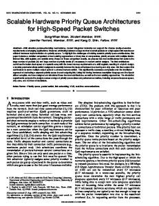
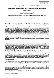
Fig. 1. Weighted round robin scheduling
A. The Weighted Round Robin Family
We begin with the active flows ”scheduled” to be served in a particular future ”time” each: flow A will be served at t=32, C at t=30, D at t=37, and F at t=55. The flow to be served next is the one that has the earliest, i.e. the minimum, scheduled service time. In our example, this is flow C; its queue only has a single packet, so after being served it becomes inactive and it is removed from the schedule. Next, ”time” advances to 32 and flow A is served. Flow A remains active after its head packet is transmitted, so it has to be rescheduled. Rescheduling is based on the inverses of the weight factors, which correspond to relative service intervals1 . The service interval of A is 20, so A is rescheduled to be served next at ”time” 32+20=52. (When packet size varies, that size also enters into the calculation of the next service time). The resulting service order is shown in figure 1. As we see, the scheduler operates by keeping track of a “next service time” number for each active flow. In each step, we must: (i) find the minimum of these numbers; and then (ii) increment it if the flow remains active (i.e. keep the flow as candidate, but modify its next service time), or (iii) delete the number if the flow becomes inactive. When a new packet of an inactive flow arrives, that flow has to be (iv) reinserted into the schedule. Many scheduling algorithms belong to this family. Workconserving disciplines always advance the ”current time” to the service time of the next active flow, no matter how far in the future that time is; in this way, the active flows absorb all the available network capacity. Non-work-conserving disciplines use a real-time clock. A flow is only served when the real-time clock reaches or exceeds its scheduled service time; when no such flow exists, the transmitter stays idle. These schedulers operate as ”regulators”, forcing each flow to obey its service contract. Other important constituents of a scheduling algorithm are the way it updates the service time of the flow that was served (e.g. based on the flow’s service interval or on some per-packet deadline), and the way it determines the service time
Figure 1 intuitively illustrates weighted round robin scheduling. Seven flows, A through G, are shown; four of them, A, C,
1 in arbitrary units; there is no need for these numbers to add up to any specific value, so they do not have to change when new flows become active or inactive.
II. A DVANCED S CHEDULING
USING
P RIORITY Q UEUES
Section I explained the need for per-flow queueing in order to provide advanced QoS in future high speed networks. To be effective, per-flow queueing needs a good scheduler. Many advanced scheduling algorithms have been proposed; good overviews appear in [Zhang95] and [Keshav97, chapter 9]. Priorities is a first, important mechanism; usually a few levels of priority suffice, so this mechanism is easy to implement. Aggregation (hierarchical scheduling) is a second mechanism: first choose among a number of flow aggregates, then choose a flow within the given aggregate [Bennett97]. Some levels of the hierarchy contain few aggregates, while others may contain thousands of flows; this paper concerns the latter levels. The hardest scheduling disciplines are those belonging to the weighted round robin family; we review these, next.
c
Copyright IEEE - to appear in IEEE/ACM Transactions on Networking (ToN), 2007
3 of newly-active flows. These issues account for the differences among the weighted fair queueing algorithm and its variants, the virtual clock algorithm, and the earliest-due-date and ratecontrolled disciplines [Keshav97, ch.9]. B. Priority Queue Implementations All of the above scheduling algorithms rely on a common computational primitive for their most time-consuming operation: finding the minimum (or maximum) of a given set of numbers. The data structure that supports this primitive operation is the priority queue. Priority queues provide the following operations: • Insert: a new number is inserted into the set of candidate numbers; this is used when (re)inserting into the schedule flows that just became active (case (iv) in section II-A). • Delete Minimum: find the minimum number in the set of candidate numbers and delete it from the set; this is used to serve the next flow (case (i)) and then remove it from the list of candidate flows if this was its last packet, hence it became inactive (case (iii)). • Replace Minimum: find the minimum number in the set of candidate numbers and replace it with another number (possibly not the minimum any more); this is used to serve the next flow (case (i)) and then update its “next service time” if the flow has has more packets, hence remains active (case (ii) in section II-A). Priority queues with only a few tens of entries or with priority numbers drawn from a small menu of allowable values are easy to implement, e.g. using combinational priority encoder circuits. However, for priority queues with many thousand entries and with values drawn from a large set of allowable numbers, heap or calendar queue data structures must be used. Other heap-like structures [Jones86] are interesting in software but are not adaptable to high speed hardware implementation. L1
30
L2
55
L3 L4
32
57 125
L1
99 81
56
37
104
L2
L3
L4
30 55 32 57 99 56 37 125 81 104
(a) 0-9 10-19 20-29 30-39 40-49 50-59 60-69 70-79 80-89 90-99
104
125
30
55
32
56
37
57
81
mod 100
99
(b)
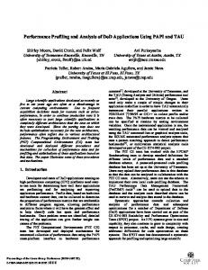
Fig. 2. Priority queues: (a) heap; (b) calendar queue
Figure 2(a) illustrates a heap. It is a binary tree (top), physically stored in a linear array (bottom). Non-empty entries are
pushed all the way up and left. The entry in each node is smaller than the entries in its two children (the heap property). Insertions are performed at the leftmost empty entry, and then possibly interchanged with their ancestors to re-establish the heap property. The minimum entry is always at the root; to delete it, move the last filled entry to the root, and possibly interchange it with descendants of it that may be smaller. In the worst case, a heap operation takes a number of interchanges equal to the tree height. Figure 2(b) illustrates a calendar queue [Brown88]. It is an array of buckets. Entries are placed in the bucket indicated by a linear hash function. The next minimum entry is found by searching in the current bucket, then searching for the next non-empty bucket. Calendar queues have a good average performance when the average is taken over a long sequence of operations. However, in the short-term, some operations may be quite expensive. In [Brown88], the calendar is resized when the queue grows too large or too small; this resizing involves copying of the entire queue. Without resizing, either the linked lists in the buckets may become very long, thus slowing down insertions (if lists are sorted) or searches (if lists are unsorted), or the empty-bucket sequences may become very long, thus requiring special support to search for the next non-empty bucket2 . C. Related Work Priority queues with up to a few tens of entries can be implemented using combinational circuits. For several tens of entries, one may want to use a special comparator-tree architecture that provides bit-level parallelism [Hart02]. In some cases, one can avoid larger priority queues. In plain round robin, i.e. when all weight factors are equal, scheduling can be done using a circular linked list3 . In weighted round robin, when the weight factors belong to a small menu of a few possible different values, hierarchical schedulers that use round robin within each weight-value class work well [Stephens99] [KaSM97]. This paper concerns the case when the weight factors are arbitrary. For hundreds of entries, a weighted round robin scheduler based on content addressable memory (CAM) was proposed in [KaSC91], and a priority queue using per-word logic (sort by shifting) was proposed in [Chao91]. Their performance is similar4 to that of our pipelined heap manager (1 operation per 1 or 2 clock cycles). However, the cost of these techniques scales poorly to large sizes. At large sizes, memory is the dominant cost (section V-D); the pipelined heap manager uses SRAM, which costs two or more times less than CAM and 2 In non-work-conserving schedulers searching for the next non-empty bucket is not a problem: since the current time advances with real time, the scheduler only needs to look at one bucket per time slot –empty buckets simply mean that the transmitter should stay idle. 3 Yet, choosing the proper insertion point is not trivial. 4 except for the following problem of the CAM-based scheduler under workconserving operation: As noted in [KaSC91, p. 1273], a method to avoid ”sterile” flows should be followed. According to this method, each time a flow becomes ready, its weight factor is ”ANDed out” of the sterile-bit-position mask; conversely, each time a flow ceases being ready, the bit positions corresponding to its weight factor may become sterile, but we don’t know for sure until we try accessing them, one by one. Thus, e.g. with 16-bit weights, up to 15 ”sterilityprobing” CAM accesses may be needed, in the worst case, after one such flow deletion and before the next fertile bit position is found. This can result in service gaps that are greater than the available slack of a cell’s transmission time.
c
Copyright IEEE - to appear in IEEE/ACM Transactions on Networking (ToN), 2007
4 much less than per-word logic. Other drawbacks are the large power consumption of shifting the entire memory contents in the per-word-logic approach, and the fact that CAM often requires full-custom chip design, and thus may be unavailable to semi-custom ASIC designers. A drawback of the CAM-based solution is the inability to achieve smooth service among flows with different weights. One source of service-time jitter for the CAM-based scheduler is the uneven spreading of the service ”cycles” on the time axis. As noted in [KaSC91, p. 1273], the number of non-service cycles between two successive service cycles may be off by a factor up to two relative to the ideal number. A potentially worse source of jitter is the variable duration of each service cycle. For example, if flow A has weight 7 and flows B through H (7 flows) have weight 1 each, then cycles 1 through 3 and 5 through 7 serve flow A only, while cycle 4 serves all flows; the resulting service pattern is AAAABCDEFGHAAA-A..., yielding very bad jitter for flow A. By contrast, some priority-queue based schedulers will always yield the best service pattern, ABACADAEAFAGAH-AB..., and several other priority-queue based schedulers will yield service patterns in between the two above extremes. For priority queues with many thousands of entries, calendar queues are a viable alternative. In high-speed switches and routers, the delay of resizing the calendar queue –as in [Brown88]– is usually unacceptable, so a large size is chosen from the beginning. This large size is the main drawback of calendar queues relative to heaps; another disadvantage is their inability to maintain multiple priority queues in a way as efficient as the forest of heaps presented in section III-D. The large size of the calendar helps to reduce the average number of entries that hash together into the same bucket. To handle such collisions, linked lists of entries, pointed to by each bucket, could be used, but their space and complexity cost is high. The alternative that is usually preferred is to store colliding entries into the first empty bucket after the position of initial hash. In a calendar that is large enough for this approach to perform efficiently, long sequences of empty buckets will exist. Quickly searching for the next non-empty bucket can be done using a hierarchy of bit-masks, where each bit indicates whether all buckets in a certain block of buckets are empty [Kate87] [Chao97] [Chao99]. A similar arrangement of bit flags can be used to quickly search for the next empty bucket where to write a new entry; here, each bit in the upper levels of the hierarchy indicates whether all buckets in a certain block are full. Calendar queues can be made as fast as as our pipelined heap manager, by pipelining the accesses to the multiple levels of the bit mask hierarchy and to the calendar buckets themselves; no specific implementations of calendar queues at the performance range considered in this paper have been reported in the literature, however. The main disadvantage of calendar queues, relative to heaps, is their cost in silicon area, due to the large size of the calendar array, as explained above. To make a concrete comparison, we use the priority queue example that we implemented in our ASIC core (section V-D): it has a capacity of 16K entries (flows) – hence the flow identifier is 14-bit wide – and the priority value has 18 bits. This priority width allows 17 bits of precision for the weight factor of each flow (the
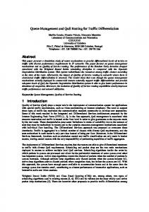
18th bit is for wrap-around protection –see section V-B); this precision suffices for the lightest-weight flow on a 10 Gb/s line to receive approximately 64 Kb/s worth of service. The equivalent calendar queue would use 217 buckets of size 14 bits (a flow ID) each; the bit masks need 217 bits at the bottom level, and a much smaller number of bits for the higher levels. The silicon area for these memories, excluding all other management circuits, for the 0.18-micron CMOS process considered in section V-D, would be 55mm2 , as compared to 19mm2 for the entire pipelined heap manager (memory plus management circuits). Finally, heap management can be performed at medium speed using a hardware FSM manager with the heap stored in an SRAM block or chip [Mavro98]. In this paper we look at highspeed heap management, using pipelining. As far as we know, no other work prior to ours ([Ioann00]) has considered and examined pipelined heap management, while a parallel and independent study appeared in [Bhagwan00]; that study differs from ours as described in section III-F. III. P IPELINING THE H EAP M ANAGEMENT Section II showed why heap data structures play a central role in the implementation of advanced scheduling algorithms. When the entries of a large heap are stored in off-chip memory, the desire to minimize pin cost entails little parallelism in accessing them. Under such circumstances, a new heap operation can be initiated every 15 to 50 clock cycles for heaps of sizes 256 to 64K entries, stored in one or two 32-bit external SRAM’s [Mavro98]5. Higher performance can be achieved by maintaining the top few levels of the heap in on-chip memory, using off-chip memory only for the bottom (larger) levels. For highest performance, the entire heap can be on-chip, so as to use parallelism in accessing all its levels, as described in this section. Such highest performance –up to 1 operation per clock cycle– will be needed e.g. in OC-192 line cards. An OC-192 input line card must handle an incoming 10 Gbit/s stream plus an outgoing (to the switching fabric) stream of 15 to 30 Gbit/s. At 40 Gbps, for packets as short as about 40 bytes, the packet rate is 125 M packets/s; each packet may generate one heap operation, hence the need for heap performance in excess of 100 M operations/s. A wide spectrum of intermediate solutions exist too, as discussed in section IV on cost-performance tradeoffs. A. Heap Algorithms for Pipelining Figure 3 illustrates the basic ideas of pipelined heap management. Each level of the heap is stored in a separate physical memory, and managed by a dedicated controller stage. The external world only interfaces to stage 1. The operations provided are (i) insert a new entry into the heap (on packet arrival, when the flow becomes non-idle); (ii) deleteMin: read and delete the minimum entry i.e. the root (on packet departure, when the flow becomes idle); and (iii) replaceMin: replace the minimum with a new entry that has a higher value (on packet departure, when the flow remains non-idle). 5 These numbers also give an indication on the limits of software heap management, when the heap fits in on-chip cache. When the processor is very fast, the cache SRAM throughput is the limiting factor; then, each heap operation costs 15 to 50 cycles of that on-chip SRAM, as compared to 1 to 4 SRAM cycles in the present design (section IV).
c
Copyright IEEE - to appear in IEEE/ACM Transactions on Networking (ToN), 2007
5 new entry min. entry to insert deleted
opcode op1 ins/del/repl
arg1
Stage 1
lastEntry
op2 ins/repl
i2
i3
i4
L1
32
57 125
99 81
L2
37
75
(a) 75
L3 30
arg4
Stage 4
56
104
arg3
Stage 3 op4 ins/repl
55
arg2
Stage 2 op3 ins/repl
30
L4
55
32
57
99
56
37
Fig. 3. Simplified block diagram of the pipeline 125
When a stage is requested to perform an operation, it performs the operation on the appropriate node at its level, and then it may request the level below to also perform an induced operation that may be required in order to maintain the heap property. For levels 2 and below, besides specifying the operation and a data argument, the node index, i, must also be specified. When heap operations are performed in this way, each stage (including the I/O stage 1) is ready to process a new operation as soon as it has completed the previous operation at its own level only. The replaceMin operation is the easiest to understand. In figure 3, the given arg1 must replace the root at level 1. Stage 1 reads its two children from L2, and determines which of the three values is the new minimum to be written into L1; if one of the ex-children was the minimum, the given arg1 must now replace that child, giving rise to a replace operation for stage 2, and so on. The deleteMin operation is similar to replace. To maintain the heap balanced, the root is deleted by replacing it with the rightmost non-empty entry in the bottom-most non-empty level6 . A lastEntry bus is used to read that entry, and the corresponding level is notified to delete it. When multiple operations are in progress in various pipeline stages, the real ”last” entry may not be the last entry in the last level: the pending value of the youngest-in-progress insert operation must be used instead. In this case, the lastEntry bus functions as a bypass path, and the most recent insert operation is then aborted. The traditional insert algorithm needs to be modified as shown in figure 4. In a non-pipelined heap, new entries are inserted at the bottom, after the last non-empty entry (fig. 4(a)); if the new entry is smaller than its parent, it is swapped with that parent, and so on. Such operations would proceed in the wrong direction, in the pipeline of figure 3. In our modified algorithm, new entries are inserted at the root (fig. 4(b)). The new entry and the root are compared; the smaller of the two stays as the new root, and the other one is recursively inserted into the proper of the two sub-heaps. By properly steering –left 6 If we did not use the last entry for the root substitution, then the smaller of the two children would be used to fill in the empty root. As this would go on recursively, leaves of the tree would be freed up arbitrarily, spoiling the balance of the tree.
81
104
(b)
Fig. 4. Algorithms for Insert: (a) traditional insertion; (b) modified insertion (top-to-bottom)
or right sub-heap– this chain of insertions at each level, we can ensure that the last insertion will be guided to occur at precisely the heap node next to the previously-last entry. The address of that target slot is known at insertion-initiation time: it is equal to the heap occupancy count plus one; the bits of that address, MS to LS, steer insertions left or right at each level. Notice that traditional insertions only proceed through as many levels as required, while our modified insertions traverse all levels; this does not influence throughput, though, in a pipelined heap manager. B. Overlapping the Operation of Successive Stages Replace (or delete) operations on a node i, in each stage of fig. 3, take 3 clock cycles each: (i) read the children of node i from the memory of the stage below; (ii) find the minimum among the new value and the two children; (iii) write this minimum into the memory of this stage. Insert operations also take 3 cycles per stage: (i) read node i from the memory of this stage; (ii) compare the value to be inserted with the value read; (iii) write the minimum of the two into the memory of this stage. Using such an execution pattern, operations ripple down the pipeline at the rate of one stage every 3 clocks, allowing an operation initiation rate no higher than 1 every 3 cycles. We can improve on this rate by overlapping the operation of stages. Figure 5 shows replace (or delete) –the hardest operation– in the case of ripple-down rate of one stage per cycle. The operation at level L has to replace value C, in node iL , by the new value C’. The index iL of the node to be replaced, as well as the new value C’, are deduced from the replace operation at level L-1, and they become known at the end of clock cycle 1, right after the comparison of the new value A’ for node iL−1 with its two children, B, and C. The comparison of C’ with its children, F and G, has to occur in cycle 2 in order to achieve the desired ripple-down rate. For this to be possible, F
c
Copyright IEEE - to appear in IEEE/ACM Transactions on Networking (ToN), 2007
6 A’, i
L-1
A
L-1
C’, i
L
B C
L
F’, iL+1
L+1
A’, i
L-1
D E F G
A’’=min{A’,B,C}
compare A’, B, C
write A’’ C’, i
L
read D, E, F, G
C’’=min{C’,F,G}
compare C’, F, G
write C’’ F’, iL+1
read C’s gr’d chld’n
compare F’, ..., ...
2
3
t 0
1
clock cycles
Fig. 5. Overlapped stage operation for replace
and G must be read in cycle 1. However, in cycle 1, index i L is not yet known –only index iL−1 is known. Hence, in cycle 1, we are obliged to read all four grand children of A (D, E, F, G) given that we do not know yet which one of B or C will need to be replaced; notice that these grand children are stored in consecutive, aligned memory locations, so they can be easily read in parallel from a wide memory. In conclusion, a rippledown rate of one stage every cycle needs a read throughput of 4 values per cycle in each memory7; an additional write throughput of 1 entry per cycle is also needed. Insert operations only need a read throughput of 1, because the insertion path is known in advance. Cost-performance tradeoffs are further analyzed in section IV. C. Inter-Operation Dependencies and Bypasses Figure 5 only shows a single replace operation, as it ripples down the pipeline stages. When more operations are simultaneously in progress, various dependencies arise. A structural dependence between write-back’s of replace and insert operations can be easily resolved by moving the write-back of insert to the fourth cycle (in figure 5, reading at level L is in cycle 0, and writing at the same level is in cycle 3). Various data dependencies also exist; they can all be resolved using appropriate bypasses. The main data dependence for an insert concerns the reading of each node. An insert can be issued in clock cycle 2 if the previous operation was issued in clock cycle 1. However, that other operation will not have written the new item of stage 1 until cycle 3, while insert tries to read it in cycle 2. Nevertheless, this item is actually needed by 7 Heap entries contain a priority value and a flow ID. Only the flow ID of the entry to be swapped needs to be read. Thus, flow ID’s can be read later than priority values, so as to reduce the read throughput for them, at the expense of complicating pipeline control.
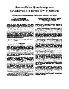
the insert only for the comparison, which takes place in cycle 3. At that time the previous operation has already decided the item of stage 1, and that can be forwarded to the insert operation. The read however is needed, since two consecutive operations can take different turns as they traverse the tree downwards, and thus they may manipulate distinct sets of elements, so that the results of the read will need to be used instead of the mentioned bypassing. Of course there is a chance that these bypasses continue as the two operations traverse the tree. The corresponding data dependence for a delete operation is analogous but harder. The difference is that delete needs to read the entries of level 2, rather than level 1, when it is issued. This makes it dependent on the updating of this level’s items, which comes one cycle after that of level 1. So, unlike insert, it cannot immediately follow its preceding operation, but should rather stall one cycle. However it can immediately follow an insert operation, as this insert will be aborted, thus creating the needed bubble separating the delete from a preceding operation. Besides local bypasses from the two lower stages (section VA), a global bypass was noted in section III-A: when initiating a deletion, the youngest-in-progress insertion must yield its value through the lastEntry bus. The most expensive set of global bypasses is needed for replacements or deletions, when they are allowed to immediately follow one another. Figure 6 shows an example of a heap where the arrangement of values is such that all four successive replacements shown will traverse the same path: 30, 31, 32, 33. In clock cycle (1), in the left part of the figure, operation A replaces the root with 40; this new value is compared to its two children, 31 and 80. In cycle (2), the minimum of the previous three values, 31, has moved up to the root, while operation A is now at L2, replacing the root of the left subtree; a new operation B reads the new minimum, 31, and replaces it with 45. Similarly, in cycle (3) operation C replaces the minimum with 46, and in cycle (4) operation D replaces the new minimum with 41. The correct minimum value that D must read and replace is 33; looking back at the system state in cycle (3), the only place where ”33” appears is in L4: the entire chain of operations, in all stages, must be bypassed for the correct value to reach L1. Similarly, in cycle (4), the new value, 41, must be compared to its two children, to decide whether it should fall or stay. Which are its correct children? They are not 46 and 80, neither 45 and 80 –these would cause 41 to stay at the root, which is wrong. The correct children are 40 and 80; again, the value 40 needs to be bypassed all the way from the last to the first stage. In general, when replacements or deletions are issued on every cycle, each stage must have bypass paths from all stages below it; we can avoid such expensive global bypasses by issuing one or more insertions, or by allowing an idle clock cycle between consecutive replacements or deletions. D. Managing a Forest of Multiple Heaps In a system that employees hierarchical scheduling (section II), there are multiple sets (aggregates) of flows. At the second and lower hierarchy levels, we want to choose a flow within a given aggregate. When priority queues are used for this latter choice, we need a manager for a forest of heaps –one heap
c
Copyright IEEE - to appear in IEEE/ACM Transactions on Networking (ToN), 2007
7 A 30
L1
40
80
31
L2
B 31
45
40
A 31
C 32 45
B 32
80
46
D 33 46
C 33
80
40
L3
50
32
99
81
50
32
99
81
50
A
32
41
80
45 99
50
81
B
33
99
81
40
L4
60 70 33
60 70 33
(1)
60 70 33
(2)
(3)
60 70 33 A
(4)
Fig. 6. Replace operations in successive stages need global bypasses
per aggregate. Our pipelined heap manager can be conveniently used to manage such a forest. Referring to figure 3, it suffices to store all the heaps ”in parallel”, in the memories L1, L2, L3, ..., and to provide an index i1 to the first stage (dashed lines), identifying which heap in the forest the requested operation refers to. Assume that N heaps must be managed, each of them having a maximum size of 2n−1 entries. Then, n stages will be needed; stage j will need a memory Lj of size N ×2j−1 . In many cases, the number of flows in individual aggregates may be allowed to grow significantly, while the total number of flows in the system is restricted to a number M much less than N × (2n − 1). In these cases, we can economize in the size of the large memories near the leaves, Ln , Ln−1 , ..., at the expense of additional lookup tables Tj ; for each aggregate a, Tj [a] specifies the base address of heap a in memory Lj . For example, say that the maximum number of flows in the system is M = 2n ; individual heaps are allowed to grow up to 2n − 1 = M − 1 entries each. For a heap to have entries at level Lj , its size must be at least 2j−1 ; at most M/2j−1 = 2n−j+1 such heaps may exist simultaneously in the system. Thus, it suffices for memory Lj to have a size of (2n−j+1 )×(2j−1 ) = 2n , rather than N ×2j−1 in the original, static-allocation case. E. Are Replace Operations needed in High Speed Switch Schedulers? Let us note at this point that, in a typical application of a heap manager in a high speed switch or router line card, replaceMin operations would not be used –split deleteMin-insert transactions would be used instead. The reason is as follows. A number of clock cycles before transmitting a packet, the minimal entry Em is read from the heap to determine the flow ID that should be served. Then, the flow’s service interval is read from a table, to compute the new service time for the flow. A packet is dequeued from this flow’s queue; if the queue remains non-empty, the flow’s entry in the heap, Em , is replaced with the new service time. Thus, the time from reading Em until replacing it with a new value will usually be several clock cycles. During these clock cycles, the heap can and must service other requests; effectively, flows have to be serviced in an interleaved fashion in order to keep up the high I/O rate. To service other requests, the next minimum entries after Em have to be read. The most practical method to make all this work is to treat the read-update pair as a split transaction: first read and delete Em
–so that the next minima can be read– then later reinsert the updated entry. F. Comparison to P-Heap As mentioned earlier, a parallel and independent study of pipelined heap management was made by Bhagwan and Lin [Bhagwan00]. The Bhagwan/Lin paper introduces and uses a variant of the conventional heap, called P-heap. We use a conventional heap. In a conventional heap, all empty entries are clustered in the bottom and right-most parts of the tree; in a P-heap, empty entries are allowed to appear anywhere in the tree, provided all their children are also empty. Bhagwan & Lin argue that a conventional heap cannot be easily pipelined, while their P-heap allows pipelined implementation. In our view, however, the main or only advantage of P-heap relative to a conventional heap, when pipelining is used, is that P-heap avoids the need for the lastEntry bypass, in figure 3; this is a relatively simple and inexpensive bypass, though. On the other hand, P-heap has two serious disadvantages. First, in a P-heap, the issue rate of insert operations is as low as the issue rate of (consecutive) delete operations, while, in our conventional heap, insert operations can usually be issued twice as frequently as (consecutive) deletes (section IV). The reason is that our insert operations know a-priori which path they will follow, while in a P-heap they have to dynamically find their path (like delete operations do in both architectures). Second, our conventional heap allows the forest-of-heaps optimization (section III-D), which is not possible with P-heaps. Regarding pipeline structure, it appears that Bhagwan & Lin perform three dependent basic operations in each of their clock cycle: first a memory read, then a comparison, and then a memory write. By contrast, this paper adopts the model of contemporary processor pipelines: a clock cycle is so short that only one of these basic operations fits in it. Based on this model, the Bhagwan/Lin issue rate would be one operation every six (6) short-clocks, as compared to 1 or 2 short-clocks in this paper. This is the reason why [Bhagwan00] need no pipeline bypasses: each operation completely exits a tree level before the next operation is allowed to enter it. IV. C OST-P ERFORMANCE T RADEOFFS A wide range of cost-performance tradeoffs exists for pipelined heap managers. The highest performance (unless one goes to superscalar organizations) is for operations to ripple
c
Copyright IEEE - to appear in IEEE/ACM Transactions on Networking (ToN), 2007
8 down the heap at one level per clock cycle, and for new operations to also enter the heap at that rate. This was discussed in sections III-B and III-C, and, as noted, requires 2-port memory blocks that are 4-entry wide, plus expensive global bypasses. This high-cost, high-performance option appears in line (i) of Table I. To have a concrete notion of memory width in mind, in our example implementation (section V) each heap entry is 32 bits –an 18-bit priority value and a 14-bit flow ID; thus, 128bit-wide memories are needed in this configuration. To avoid global bypasses, which require expensive datapaths and may slow down the clock cycle, delete (or replace) operations have to consume 2 cycles each when immediately following one another, as discussed in section III-C and noted in line (ii). In many cases this performance penalty will be insignificant, because we can often arrange for one or more insertions to be interposed between deletions, in which case the issue rate is still one operation per clock cycle. Dual-ported memories cost twice as much as single-ported memories of the same capacity and width, hence they are a prime target for cost reduction. Every operation needs to perform one read and one write-back access to every memory level, thus when using single-port memories every operation will cost at least 2 cycles: lines (iii) and below. If we still use 4-wide memories, operations can ripple down at 1 level/cycle; given that deletions cannot be issued more frequently than every other cycle, inexpensive local bypasses suffice. A next candidate to reduce cost is memory width. Silicon area is not too sensitive to memory width, but power consumption is. In the 4-wide configurations, upon deletions, we read 4 entries ahead of time, to discover in the next cycle which 2 of them are needed and which not; the 2 useless reads consume extra energy. If we reduce memory width to 2 entries, delete operations can only ripple down 1 level every 2 cycles, since the aggressive overlapping of figure 5 is no longer feasible. If we still insist on issuing operations every 2 cycles, successive delete operations can appear in successive heap levels at the same time, which requires global (expensive) bypasses (line (iv)). What makes more sense, in this lower cost configuration, is to only have local bypasses, in which case delete operations consume 3 cycles each; insert operations are easy, and can still be issued every other cycle (line (v)). A variable-length pipeline, with interlocks to avoid write-back structural hazards, is needed. More details on how this issue rate is achieved can be found in [Ioann00, Appendix A]. When lower performance suffices, single-entry-wide memories can be used, reducing the ripple-down rate to 1 level every 3 cycles. With local-only bypasses, deletions cost 4 cycles (line (vi)). Insertions can still be issued every 2 cycles, i.e. faster than the ripple-down rate, if we arrange each stage so that it can accept a second insertion before the previous one has rippled down, which is feasible given that memory throughput suffices. Lines (vii) through (x) of table I refer to the option of placing the last one or two levels of the heap (the largest ones) in offchip SRAM8 , in order to economize in silicon area. When two levels of the heap are off-chip, they share the single off-chip memory. We consider off-chip memories of width 1 or 2 heap 8 single-ported,
of course
entries. We assume zero-bus-turnaround (ZBT)9 SRAM; these accept clock frequencies at least as high as 166 MHz, so we assume no slow-down of the on-chip clock. For delete operations, issue rate is limited by the following loop delay: read some entries from a heap level, compare them to something, then read some other entries whose address depends on the comparison results. For off-chip SRAM, this loop delay is 2 cycles longer than for on-chip SRAM, hence delete operations are 2 cycles more expensive than in lines (v) and (vi). Insert operations have few, non-critical data dependencies, so their issue rate is only restricted by resource (memory) utilization: when a single heap level is off-chip their issue rate stays unaffected; when two heap levels share a single memory (lines (ix), (x)), each insertion needs 4 accesses to it, hence the issue rate is halved. V. I MPLEMENTATION We have designed a pipelined heap manager as a core integratable into ASIC’s, in synthesizable Verilog form. We chose to implement version (ii) of Table I with the 2-port, 4-wide memories, where operations ripple down at the rate of one stage per cycle. The issue rate is one operation per clock cycle, except that one or more insertions or one idle (bubble) cycle is needed between successive delete operations in order to avoid global bypasses (section III-C). Replace operations are not supported, for the reason explained in section III-E (but can be added easily). Our design is configurable to any size of priority queue. The central part of the design is one pipeline stage, implementing one tree level; by placing as many stages as needed next to each other, a heap of the desired size can be built. The first three and the last one stages are variations of the generic (central) pipeline stage. This section describes the main characteristics of the implementation; for more details refer to [Ioann00]. A. Datapath The datapath that implements insert operations is presented in figure 7 and the datapath for delete operations is in figure 8. The real datapath is the merger of the two. Only a single copy of each memory block, L2, L3, L4, L5, exists in the merged datapath, with multiplexors to feed its inputs from the two constituent datapaths. The rectangular blocks in front of memory blocks are pipeline registers, and so are the long, thin vertical rectangles between stages. The rest of the two datapaths are relatively independent, so their merger is almost their sum. Bypass signals from one to the other are labeled I2, I3,...; D2, D3,.... These signals pass through registers on their way from one datapath to the other (not shown in the figures). In figure 7, the generic stages are number 3 and below. Stage 1 includes interface and entry count logic, also used for insertion path evaluation. In the core of the generic stage, two values are compared, one flowing from the previous stage, and one read from memory or coming from a bypass path. The smaller value is stored to memory, and the larger one is passed to the next stage. Bit manipulation logic (top) calculates the next read address. In figure 8, the generic stages are number 4 and below. The four children that were read from memory in the previous 9 IDT
trademark; see e.g. http://www.micron.com/mti/msp/html/zbtds.html
c
Copyright IEEE - to appear in IEEE/ACM Transactions on Networking (ToN), 2007
9 Pipelined Heap Cost-Performance Tradeoffs COST
L I N E (i) (ii) (iii) (iv) (v) (vi) (vii) (viii) (ix) (x)
On-Chip SRAM num. of Width Ports (entries) 2 4 2 4 1 4 1 2 1 2 1 1 1 1 1 1 1 1 1 1
Bypass Path Complexity global local local global local local local local local local
Off-Chip SRAM Width Levels (entries) contained 2 1 1 1 2 2 1 2
1 (CP I)
P erf ormance Cycles per Cycles Per Delete Op Insert Op 1 1 1 or 2 1 2 2 2 2 3 2 4 2 5 2 6 2 5 4 6 4
TABLE I C OST-P ERFORMANCE T RADEOFFS W ITH VARIOUS M EMORY C ONFIGURATIONS & C HARACTERISTICS .
stage feed multiplexors that select two of them or bypassed values; selection is based on the comparison results of the previous stage. The two selected children and their parent (passed from the previous stage) are compared to each other using three comparators. The results affect the write address and data, as well as the next read address. B. Comparing Priority Values under Wrap-around Arithmetic comparisons of priorities must be done carefully, because these numbers usually represent time stamps that increase without bound, hence they wrap-around from large back to small values. Assume that the maximum priority value stored in the heap, viewed as an infinite-precision number, never exceeds the stored minimum by more than 2p − 1. This will be true if, e.g., the service interval of all flows is less than 2p , since any inserted number will be less than m + 2p , where m was a deleted minimum, hence no greater than the current minimum. Then, we store priority values as unsigned (p + 1)-bit numbers. When comparing two such numbers, A and B, if A-B is positive but more than 2p , it means than B is actually larger than A but has wrapped around from a very large to a small value. C. Verification In order to verify our design, we wrote three models of a heap, of increasing level of abstraction, and we simulated them in parallel with the Verilog design, so that each higher-level model checked the correctness of the next level, down to the actual design. The top level model, written in Perl, is a priority queue that just verifies that the entry returned upon deletions is the minimum of the entries so far inserted and not yet deleted. The next more detailed model, written in C, is a plain heap; its memory contents must match those of the Verilog design for test patterns that do not activate the insertion abortion mechanism (section III-A). However, when this latter mechanism is activated, the resulting layout of entries in the pipelined heap may differ from that in a plain heap, because some insertions are
aborted before they reach their ”equilibrium” level, hence the value that replaces the root on the next deletion may not be the maximum value along the insertion path (as in the plain heap), but another value along that path, as determined by the relative timing of the insert and delete operations. Our most detailed C model precisely describes this behavior. We have verified the design with many different operation sequences, activating all existing bypass paths. Test patterns of tens of thousands of operations were used, in order to test all levels of the heap, also reaching saturation conditions. D. Implementation Cost and Performance In an example implementation that we have written, each heap entry consists of an 18-bit priority value and a 14-bit flow identifier, for a total of 32 bits per entry. Each pipeline stage stores the entries of its heap level in four 32-bit two-port SRAM blocks. We have processed the design through the Synopsys synthesis tool to get area and performance estimates. For a 16 K entry heap, the largest SRAM blocks are 2K × 32. The varying size of the SRAM blocks in the different stages of the pipeline does not pose any problem: modern ASIC tools routinely perform automatic, efficient placement and routing of system-ona-chip (SoC) designs that are composed of multiple, heterogeneous sub-systems of random size each. Most of the area for the design is consumed by the unavoidable on-chip memory. For the example implementation mentioned above, the memory occupies about 3/4 of the total area. The datapath and control of the general pipeline stage has a complexity of about 5.5 K gates10 plus 500 bits worth of flipflops and registers. As mentioned, the first stage differs significantly from the general case, being quite simpler. If we consider the first stage together with the extra logic after the last stage, the two of them approximately match the complexity of one general stage. Thus, we can deduce a simplified formula 10 simple
2-input NAND/NOR gates
c
Copyright IEEE - to appear in IEEE/ACM Transactions on Networking (ToN), 2007
10 Stage 3
*2
MS *2
+
I2
root
RA
Din
WA
L2
D2
RA
*2
+
MS *2
+
I4
Din
WA
RA
L3
D3
(