University of Pennsylvania
ScholarlyCommons Departmental Papers (CIS)
Department of Computer & Information Science
3-2015
Platform-Specific Timing Verification Framework in Model-Based Implementation BaekGyu Kim University of Pennsylvania,
[email protected]
Lu Feng University of Pennsylvania,
[email protected]
Linh T. X. Phan University of Pennsylvania,
[email protected]
Oleg Sokolsky University of Pennsylvania,
[email protected]
Insup Lee University of Pennsylvania,
[email protected]
Follow this and additional works at: http://repository.upenn.edu/cis_papers Part of the Computer Engineering Commons, Software Engineering Commons, and the Theory and Algorithms Commons Recommended Citation BaekGyu Kim, Lu Feng, Linh T. X. Phan, Oleg Sokolsky, and Insup Lee, "Platform-Specific Timing Verification Framework in ModelBased Implementation", Proceedings of Design, Automation & Test in Europe (DATE 2015) , 235-240. March 2015.
Design, Automation & Test in Europe (DATE 2015) , Grenoble, France, March 9 - 13, 2015 This paper is posted at ScholarlyCommons. http://repository.upenn.edu/cis_papers/784 For more information, please contact
[email protected].
Platform-Specific Timing Verification Framework in Model-Based Implementation Abstract
In the model-based implementation methodology, the timed behavior of the software is typically modeled independently of the platform-specific timing semantics such as the delay due to scheduling or I/O handling. Although this approach helps to reduce the complexity of the model, it leads to timing gaps between the model and its implementation. This paper proposes a platform-specific timing verification framework that can be used to formally verify the timed behavior of an implementation that has been developed from a platformindependent model. We first describe a way to categorize the interactions among the software, a platform, and the environment in the form of implementation schemes. We then present an algorithm that systematically transforms a platform-independent model into a platform-specific model under a given implementation scheme. This transformation algorithm ensures that the timed behavior of the platform-specific model is close to that of the corresponding implementation. Our case study of an infusion pump system shows that the measured timing delay of the system is bounded by the formally verified bound of its platform-specific model. Keywords
formal specification, program verification, scheduling, software metrics, timing, I/O handling, formal verification, infusion pump system, model complexity, model-based implementation methodology, platformindependent model, platform-specific model, platform-specific timing semantics, platform-specific timing verification framework, scheduling, timing delay, Automata, Computational modeling, Delays, Semantics, Software, Synchronization Disciplines
Computer Engineering | Computer Sciences | Software Engineering | Theory and Algorithms Comments
Design, Automation & Test in Europe (DATE 2015) , Grenoble, France, March 9 - 13, 2015
This conference paper is available at ScholarlyCommons: http://repository.upenn.edu/cis_papers/784
Platform-Specific Timing Verification Framework in Model-Based Implementation BaekGyu Kim
Lu Feng Linh T.X. Phan Oleg Sokolsky Insup Lee University of Pennsylvania Email: {baekgyu,lufeng,linhphan,sokolsky,lee}@cis.upenn.edu
Abstract—In the model-based implementation methodology, the timed behavior of the software is typically modeled independently of the platform-specific timing semantics such as the delay due to scheduling or I/O handling. Although this approach helps to reduce the complexity of the model, it leads to timing gaps between the model and its implementation. This paper proposes a platform-specific timing verification framework that can be used to formally verify the timed behavior of an implementation that has been developed from a platform-independent model. We first describe a way to categorize the interactions among the software, a platform, and the environment in the form of implementation schemes. We then present an algorithm that systematically transforms a platform-independent model into a platform-specific model under a given implementation scheme. This transformation algorithm ensures that the timed behavior of the platform-specific model is close to that of the corresponding implementation. Our case study of an infusion pump system shows that the measured timing delay of the system is bounded by the formally verified bound of its platform-specific model.
I. I NTRODUCTION Model-based implementation is an effective approach to systematically develop real-time embedded software. In this approach, the timed behavior of the software is modeled using modeling languages (e.g., UPPAAL), and the model’s conformance to the timing requirements is formally verified using verification techniques (e.g., model checking). The code generation process then automatically generates source code from the verified model, so that the final implemented system (which executes the generated code on an embedded platform) also conforms to the timing requirements. The timed behavior of the software is closely connected with the behavior of its platform; for instance, the response time of an input event from the environment depends on the task scheduling and I/O handling mechanisms of the platform. Hence, to ensure that the implemented system meets the timing requirements, the modeling and verification stage must consider the timing interactions between the software and the platform. This is non-trivial, as not only is the platform-specific timing information usually not available in this stage, but capturing all details of the platform would also make the model too complex to verify efficiently. A common solution is to model the software and the platform separately, while considering their interactions when composing the generated code with the platform. However, this separation of concerns can lead to timing gaps between the platform-independent model and its implemented system. For example, depending on the specific platform support, the code may read environmental inputs through either a polling or an interrupt-based mechanism, each of which will add a different delay to the code’s outputs; as a result, even if the the timing requirements between the code’s inputs and outputs are verified to satisfy in the platform-independent model, they may no longer hold in the implemented system. A number of efforts have been made to bridge the above timing gaps, e.g., by adding platform aspects to the high-level models. Most notably, existing work on the implementability *This research was supported in part by the DGIST Research and Development Program of the Ministry of Science, ICT and Future Planning of Korea (CPS Global Center), NSF CNS-1035715, NSF CNS-1117185, and James S. McDonnell Foundation Postdoctoral Fellowship.
of timed automata (TA) incorporates the platform information by explicitly modeling the execution platform [3], [4], [18] or by modifying the TA semantics to reflect the implementation platform semantics (e.g., [13], [14], [19]). Real-time scheduling has also been combined with TA in [2], and a number of automata- and actor-oriented scheduling interfaces have also been developed [5], [8], [17]. However, these existing techniques consider rather restrictive platform semantics, such as assuming only a small subset of possible implementations [4] or ignoring various sources of timing delays [3], [18], [19]. In the prior work [9], we studied how the timing behavior of the implementation can be formally verified by measuring the platform-specific delays, and reflecting the measured delays to the original model for model checking. In [12], we presented a timing testing method that enables one to measure more refined platform-specific delay segments in a systematic way. However, we didn’t consider explicit platform models in those previous works. In order to reason about the timing behavior of the implementation more accurately, we need to build a more refined platform model that captures the complex interactions between platform-specific features. In this paper, we present a platform-specific timing verification framework for verifying the timed behavior of an implemented system that is developed from a platform-independent model. In this framework, we model the timed behavior of a platform using an implementation scheme, which defines how the platform interacts with the platform-independent code and with the environment. Specifically, an implementation scheme specifies how a platform (i) executes the platformindependent code (e.g., periodic or aperiodic execution), (ii) reads sensor inputs from and writes actuator outputs to the environment (e.g., sampling or interrupt-based mechanism), and (iii) delivers the processed sensor inputs to and receives computed outputs from the platform-independent code (e.g., buffering or shared variable mechanism). From a platformindependent model (PIM ) and an implementation scheme for the platform, we then systematically construct the corresponding platform-specific model (PSM ) that captures the timed behavior of the corresponding implemented system. By verifying this PSM , we can now determine whether the implemented system satisfies the timing requirements. In summary, we make the following contributions: • a general category of implementation schemes for the platform based on Parnas’ four variable formalism [16] (Section III); • a modular transformation algorithm for systematically transforming a PIM into a PSM that is extensible to a range of implementation schemes (Sections IV+V); and • an infusion pump system case study, which demonstrates that the timed behavior of the PSM is sufficiently close to that of the implemented system (Section VI). II.
P ROBLEM S TATEMENT AND A PPROACH OVERVIEW
A. Motivating Example: Infusion Pump System An infusion pump is a safety-critical medical device that injects drugs into a patient’s body in a controlled manner for medical purposes, such as diabetes treatments or anesthesia. Its hardware platform is equipped with sensors (e.g., a bolus
request button) and actuators (e.g., a pump motor) to interact with its physical environment (e.g., a patient). For example, a patient presses a bolus request button to request an additional amount of drugs; a pump rotates a pump-motor that generates physical forces to move a loaded syringe so that drug can flow from the syringe to the patient. The software operating on the platform reads sensor inputs (e.g., a patient’s bolus requests) and writes actuator outputs (e.g., the rotation of a pump motor) to make infusion administration processes happen. Consider the following timing requirement from [1]: • (REQ1) “When a patient requests a bolus, a bolus infusion should start within 500ms.”1 Fig. 1 shows an UPPAAL [7] model that abstracts the timed behavior of the infusion pump software and its environment. This model is a parallel composition of two automata, M and ENV. M models the software using a clock variable (x), input synchronizations (m-BolusReq and m-EmptySyringe), and output synchronizations (c-StartInfusion, c-StopInfusion and c-Alarm). ENV models the environment using a clock variable (env-x) and the complementary synchronizations with that of M. 2 One can easily verify that the model in Fig. 1 satisfies REQ1 (by describing REQ1 as a logic formula stating that the maximum delay between two successive synchronizations, m-BolusReq followed by c-StartInfusion, does not exceed 500 time units, and then verifying it using model checking).
(1) M
Fig. 1.
(2) ENV
A platform-independent model of the infusion pump software
Using available code generators (e.g., [6] [15]), we can systematically generate the source code for the software from the verified model. The generated code repeatedly performs a series of interactions with a platform: (1) waiting for being invoked by a platform, (2) reading inputs from a platform, (3) computing outputs (which involves finding a transition to be taken using the inputs and the clocks’ values), and (4) writing the computed outputs to a platform. Observe that the platform-specific interactions between the code and a platform are not specified in the above UPPAAL model (which is the reason we call this model a platformindependent model (PIM )). For instance, the model does not capture how the platform reads a bolus request from a patient and how the platform processes this input into a program input to be read by the code. Depending on which scheme the platform uses, the response time to the patient’s request can vary, which can make the timed behavior of the implementation deviate from that of the PIM . Hence, although REQ1 is satisfied in the PIM , this timing requirement may not hold in the implemented system due to the timing deviation. B. Problem Statement To describe the problem more precisely, we first introduce some notations. Code(PIM ) denotes the platform-independent code generated from a PIM . This code needs to be composed 1 Note that the specific timing parameter (500ms) is added to the original requirement to explain our work. 2 More details about the model semantics can be found in the technical report [11].
with platform-specific primitives (e.g., read/write API) to realize the platform-specific interactions. IS denotes an implementation scheme that is used for such a composition. The implemented system is denoted by Code(PIM )kimp IS , which indicates that the resulting implementation is the platformindependent code executed with the support of an implementation scheme IS . Finally, P(∆mc ) denotes a timing requirement that the delay between an input m and an output c must be within ∆mc time units (e.g., the delay between the bolus request and the start infusion must be within 500ms). As explained in the infusion pump example, the timing information of a chosen IS is not explicitly modeled in the PIM and hence, the following claim may not always hold: PIM |= P(∆mc ) implies Code(PIM )kimp IS |= P(∆mc ). To better describe the timed behavior of the implementation, we need a platform-specific version of the PIM that captures the timed behavior of the IS , such that if this platform-specific model (PSM ) is verified to meet a timing requirement, then its implementation also satisfies the requirement. In addition, as was discussed earlier, the IS may introduce an additional delay to the response time between an input m and an output c, which can lead to violation of the timing requirement P(∆mc ) in the implementation. To quantify how close the implementation is from satisfying P(∆mc ), we would like to compute a new delay bound ∆0mc for which P(∆0mc ) holds in the implementation. In other words, we need to derive a platform-specific model (PSM ) and a bound ∆0mc such that PSM |= P(∆0mc ) implies Code(PIM )kimp IS |= P(∆0mc ). To this end, our goals are (1) to identify the necessary information to obtain such an PSM , (2) to develop a method for systematically transforming a PIM into a PSM based on the identified information, and (3) to compute the bound ∆0mc . C. Approach overview We assume that a platform consists of several building blocks to support the execution of Code(PIM ), including the InputDevice that processes inputs generated from the environment, the Output-Device that processes outputs generated from Code(PIM ), and the Code-Execution that invokes Code(PIM ) to perform transitions based on the environmental inputs and the clocks’ values. Fig. 2-(a) shows the block diagram that illustrates these blocks in an implemented system. Code(PIM)
MIO o
i
o
i
Code Execution Input Device
EXEIO
Output Device c
m Real Environment (a) Implementation
IFOC
IFMI
c
m ENVMC
(b) Platform-Specific Model (PSM)
Fig. 2. The mapping between (a) the implemented system and (b) its platformspecific model
To model the platform-specific information, we propose a general category of implementation schemes that lists possible mechanisms to implement each interaction of the platform with the environment and with the Code(PIM ). A platform can select a particular combination of mechanisms from the category as its implementation scheme. Based on a chosen implementation scheme IS , we can systematically transform a PIM into a PSM . The transformed PSM is the parallel composition of the UPPAAL models shown in Fig. 2-(b) (i.e., MIO kIFMI kIFOC kEXEIO kENVMC ). Here, IFMI and IFOC model the platform-specific input and output processing mechanisms for interacting with the environment (modeled
as ENVMC ). EXEIO models the platform-specific invocation mechanism to schedule the platform-independent code so as to receive (deliver) the code’s inputs (outputs) from (to) a platform. Finally, MIO models the timed behavior of the platform-independent code executing with the support of the implementation scheme IS . Each of these models is matched to its respective building block shown in Fig. 2-(a). Our transformation algorithm is modular and preserves the original structure of the PIM . The algorithm ensures that the resulting PSM has a similar timed behavior3 to that of the Code(PIM )kimp IS . Based on the obtained PSM , we can verify whether the delay between an input m and an output c is bounded; if so, we derive the delay bound ∆0mc from the total processing delays of the Input-Device, the Code-Execution, and the Output-Device. By verifying the PSM against the timing requirement P(∆0mc ), we can formally check whether the implementation meets this relaxed timing requirement. III.
I MPLEMENTATION S CHEMES
We define implementation schemes using the four-variables formalism proposed by Parnas [16]. As illustrated in Fig. 2-(a), the platform’s interactions occur at two system boundaries: (1) the mc-boundary, which is the boundary between the platform and the environment, and (2) the io-boundary, which is the boundary between the platform and the Code(PIM ). At the mc-boundary, the Input-Device reads environmental inputs stored in the monitored variables (m), processes the inputs, and writes the processed inputs to the input variables (i). In addition, the Output-Device reads the code execution’s outputs from the output variables (o), processes these outputs, and delivers the processed outputs to the environment by writing to the controlled variables (c). At the io-boundary, the Code(PIM ) is invoked by the CodeExecution to read the processed inputs stored in the i-variables. After performing the execution, the Code(PIM ) writes outputs to the o-variables. The information flows from the environment to the Code(PIM ) and vice versa are illustrated in Fig. 2-(a). An implementation scheme defines a mechanism for implementing each interaction at the two system boundaries: Definition 1 (Implementation Scheme). An implementation scheme is a pair {MC , IO}, where • •
MC specifies a reading (writing) mechanism and associated parameters for each variable v ∈ m∪o (v 0 ∈ i∪c); IO specifies a reading (writing) mechanism and associated parameters for each variable v ∈ i (v 0 ∈ o), as well as an invocation mechanism for the Code(PIM ).
The category of reading, writing and invocation mechanisms, as well as the platform-specific parameters required by the mechanisms, is available in [11]. Example 1 gives a possible implementation scheme formed by selecting different mechanisms from this category. The timed behavior of the implementation with this scheme is illustrated by Fig. 3. Example 1 (IS1 ). The implementation scheme 1 is given by IS 1 = {MC 1 , IO 1 }, where: (1) MC 1 (v) = h(pulse signal, interrupt, rising-edge); (delaymin = 1, delaymax = 3)i and MC 1 (v 0 ) = h(pulse signal); (delaymax = 1, delaymax = 3)i for all v ∈ m ∪ o, and v 0 ∈ i ∪ c; and (2) IO 1 (v) = h(Buffers, Read-all); (buffer-size = 5)i for all v ∈ i ∪ o, and IO 1 (invoke) = h(Periodic invocation); (period = 100)i. We now explain the implementation schemes in detail. 3 We use the term “similar timed behavior” since it requires further assumptions to argue that the implementation shows exactly the “same timed behavior” with the PSM in a strict sense.
A. The mc-boundary interactions An implementation scheme for the Input-Device specifies (1) what types of input signals are generated from the environment (in the form of m-variables), (2) how the Input-Device reads these input signals and delivers the processed inputs to Code(PIM ) (in the form of i-variables), and (3) the minimum and maximum delays – represented by the platform-specific parameters delaymin and delaymax – that the Input-Device takes to transform an input signal to a program value that can be read by the Code(PIM ). Similar information can be defined by an implementation scheme for the Output-Device. There are three types of input signals generated by the environment: pulse signals, signals with a sustained duration, and signals sustained until being read. The Input-Device can read signals using either a polling or an interrupt-based mechanism. We explain below the pulse signal (used by IS1 ). A pulse signal generated from the environment does not have a sustained duration, i.e., its sustained duration is too short to be captured through a polling-based mechanism. Therefore, a platform can only read the signal using an interrupt-based mechanism, in which an interrupt service routine is automatically called for processing the input signal whenever a signal change is detected on a sensor. For instance, an infusion pump needs to detect drug-drops using a drop sensor to precisely calculate the volume of drugs infused; since a drug-drop passes the sensor very fast, this detection is typically done using an interrupt-based mechanism. Fig. 3 illustrates three pulse signals (m1 , m2 , m3 ) that are read by a platform using an interrupt-based mechanism, as well as the timing of the three processed inputs (i1 , i2 , i3 ). In the figure, the directional arrows from ENV to Platform indicate that the input events (mi ) trigger their corresponding interrupt service routines registered in the platform. B. The io-boundary interactions An implementation scheme for the interactions at the ioboundary specifies (1) how the Code(PIM ) is invoked for its execution by a platform, and (2) how the Code(PIM ) receives inputs from the Input-Device and delivers outputs to the Output-Device. The Code(PIM ) can be invoked by a platform either periodically or aperiodically; in the former case, the period is specified by the platform-specific parameter period. Fig. 3 illustrates five consecutive periodic invocations of Code(PIM ). Whenever being invoked (illustrated as five boxes in the timeline of Code(PIM ) of Fig. 3), the Code(PIM ) receives inputs from the Input-Device through either shared variables or buffers. In the case of using a buffer, the maximum buffer size is specified by the parameter buffer-size. In addition, Code(PIM ) can either read a single input or all inputs from the buffer upon every invocation, with each choice requiring different sets of inputs to make transition decisions. For example, in Fig. 3, when the Code(PIM ) makes a transition decision at the 4th invocation, it uses a single input value (i2 ) if the read-one policy is used; on the contrary, it uses two input values (i2 and i3 ) if the read-all policy is used. The same set of mechanisms as above can be used by the Code(PIM ) to deliver outputs to the Output-Device. Discussions. Different implementation schemes lead to different delays from the instant the environment generates an input signal until the instant the Code(PIM ) reads the processed input. For example, using a polling mechanism for detecting the environmental input (m-variables) can prolong the reading up to the next polling time, and using an aperiodic invocation for the Code(PIM ) can reduce the delay by invoking Code(PIM ) immediately whenever the processed input is inserted to the
ENV
Platform
m1
Code(PIM)
Invocation Interval
(m1, t1)
m2 (m2, t2)
Fig. 3.
ENV Read: Null Read: Null
i1 Read i2 i3
Read Read
Time
M
2
m3 (m3, t3)
1
(a) PIM timed behavior
Read: Null Read: Null
3
4
5
Read: i1
Read: i1
Read: i2
Read: i2, i3
Read: i3
mk?
ck!
mk!
ck?
(b) PSM timed behavior
IFMI
[
mk? enq(ik)
EXEIO MIO
Read: Null
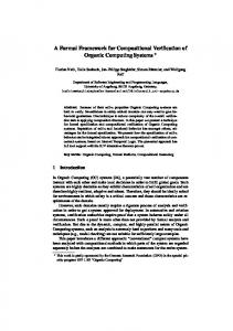
Definition 2 (PIM ). A PIM is defined as M k ENV , where M and ENV are the UPPAAL automata modeling the software and the environment, respectively. Further, M = (L, l0 , C, A, E, I), where: L is a set of locations; l0 is an initial location; C is a set of clocks; A = Am ∪ Ac , where Am = {m1 , ... , mk } is a set of input synchronizations and Ac = {c1 , ... , cj } is a set of output synchronizations; E is a set of transitions; and I is a set of invariants. Note that the input and output synchronizations in Definition 2 are expressed using m and c variables only, which implies that the interactions between M and ENV occur at the mc-boundary and that the interactions at the io-boundary are not captured by the PIM . Definition 3 (PSM ). A PSM is defined as the network of UPPAAL automata MIO k IFM I1 k ... k IFM Ik k IFOC1 k ... k IFOCj k EXEIO k EN VM C . The definition of each automaton in Definition 3 is explained in Section II-C. Note that a subscript of each automaton specifies a system boundary where the interactions occur. For example, MIO and EXEIO model the interactions at the ioboundary; IFM Ik and IFOCj model the interactions at both the mc-boundary and io-boundary; and ENVMC models the interactions at the mc-boundary. Such interactions are modeled using either channel synchronizations or variables in UPPAAL semantics.
ENVMC
Fig. 4.
]
deq(ik), ik!
enq(ok), ok?
ik?
ok!
[
IFOC
The illustration of the mc and io-boundary interactions of IS1
buffer. Due to space constraints, we do not discuss all possible combinations here. Note that our platform characterization is motivated by Altisen and Sifakis’s work [3], [4], [18] (which also studied how a platform can be abstracted and composed with the platform-independent model), but we aim at capturing more detailed timed behavior of different platforms. Specifically, the techniques in [3], [4], [18] consider a much smaller subset of possible implementations compared to our technique, and they also cannot capture scenarios that our framework can describe and formally verify. For example, they do not consider the buffer communication scheme, and they cannot capture the following scenario: Although a platform successfully detects an input from the environment, the platform-independent code may not be able to receive it due to a buffer overrun. IV. M ODULAR T RANSFORMATION FROM PIM TO PSM Our transformation algorithm takes as inputs a PIM and an implementation scheme (IS ), and it returns a PSM that has a similar timed behavior to that of the implementation Code(PIM )kimp IS . The algorithm is modular, as it preserves the structure of the PIM for any implementation scheme defined in Section III. This modularity makes the platformspecific timing verification possible for a range of implementation schemes that an arbitrary target platform may choose to execute the Code(PIM ). Before describing the algorithm, we first discuss the timed behavior of the PSM that the algorithm constructs from the PIM and the IS .
Time
mk!
deq(ok)
]
ck! ck?
Illustration of the timed behaviors of the PIM and PSM .
Fig. 4 illustrates the different timed behaviors of the PIM and the PSM . As shown in the figure, in the PIM , M is directly synchronized with ENV at the mc-boundary: whenever an input is triggered (mk !), M can immediately accept it (mk ?); similarly, whenever M produces an output (ck !), the output is immediately visible to the environment (ck ?). However, in the PSM , MIO (which will be constructed from M ) is indirectly synchronized with the environment ENVMC via a platform whose behavior is abstracted as the parallel composition of IFMI (input interface), IFOC (output interface), and EXEIO (code execution) automata. Specifically, when an input is triggered (mk !), it is first read (mk ?), processed, and enqueued to a buffer by IFMI . The buffered input is then dequeued by EXEIO , which also performs the synchronization with MIO (ik !). Subsequently, MIO produces the corresponding output and enqueues the output to a buffer at the io-boundary. Finally, IFOC dequeues the output, processes it, and makes the processed output visible to ENVMC (ck !). We next explain the basic idea for constructing a PSM with the above timed behavior; a detailed construction algorithm and examples can be found in [11]. We focus on a transformation algorithm that is compatible with the implementation scheme IS1 in Example 1; algorithms compatible for other schemes can be designed similarly. (1) Construction of MIO and ENVMC : MIO remains syntactically the same as M , except that its synchronizations are renamed from m to i, and from c to o. For example, the input synchronization m-BolusReq in Fig. 1-(1) is renamed to i-BolusReq, and the output synchronization c-StartInfusion is renamed to o-StartInfusion. In contrast, the environment model ENVMC remains exactly the same under the current implementation scheme. The desynchronization between MIO and ENVMC described earlier results in some missing information in connecting the input and output data flows across the two system boundaries. We introduce the input and output interface automata that fill such information below. (2) Construction of IFMI and IFOC : IFMI (IFOC ) is an input (output) interface automaton that models the data flow from m to i (from o to c), which is performed by the Input-Device (Output-Device). This automaton models (1) the platform-specific delays introduced when converting an environmental input to a program input (a program output to an environmental output), and (2) the communication mechanism used to deliver a program input to the Code(PIM ) (a program output to the platform). We explain the construction of IFMI below; IFOC can be constructed in the same manner. Fig. 5-(1) shows the automaton IF MI BolusReq constructed from M in Fig. 1 and IS1 . At the location Idle, the InputDevice is ready to read an input mj from ENVMC . At the location Processing, the Input-Device is currently processing the input mj that has been read from ENVMC . Once the
(1) IFMI_BolusReq
(2) IFOC_StartInfusion
Fig. 5.
The input and output interface automata for PSM
input mj is read (when a transition from Idle to Processing is taken), a processed input is ready within delaymin and delaymax time units, as specified by IS1 . A processed input is delivered to the Code(PIM ) through a finite buffer whose size is defined in the parameter buffer-size. Therefore, there are two cases when the processed input needs to be inserted into the buffer: (1) the buffer has an empty slot, and (2) the buffer is full. These two cases are modeled as the two respective transitions from Processing to Idle. Fig. 5-(2) shows the automaton IF OC StartInfusion , which models the output data flow from the Code(PIM ) to the platform. (More details can be found in [11].) (3) Construction of EXEIO : Observe that the buffer communication scheme prevents MIO from directly synchronizing with IFMI and IFOC ; for instance, the automaton IF MI BolusReq in Fig. 5-(1) is synchronized with ENVMC through the m-BolusReq channel, but there is no synchronization with MIO over the i-BolusReq channel. In other words, once an input (output) is written to a buffer by the Input-Device (Code(PIM )), the Code(PIM ) (Output-Device) does not need to read the input (output) immediately. These situations are illustrated in Fig. 4 as the two timing gaps: (1) the time passage between enq(ik ) and deq(ik ), and (2) the time passage between enq(ok ) and deq(ok ). The timing for these buffer read/write operations is closely tied to the invocation mechanism of Code(PIM ), since these operations can only occur while Code(PIM ) is being invoked by a platform. Our algorithm constructs an automaton EXEIO that models the resulting timed behavior under the periodic invocation and the synchronizations with MIO . Fig. 6 shows the EXEIO automaton, which is constructed as follows. We first create six locations that correspond to the execution stages of the Code(PIM ): Waiting indicates that the Code(PIM ) is waiting for an invocation; Active indicates that the Code(PIM ) has been invoked and is ready for execution; the remaining four locations indicate that the respective computations -read input, compute transitions, write output- are being performed. Then, necessary input and output transitions are added to the constructed locations in a way the following semantics are realized: For each transition associated with either an input or an output synchronization in MIO , we add a complementary transition in EXEIO and associate it with the conjunction of three guard conditions: (1) MIO is in a location that can read the input (or write the output), and (2) the original guard condition of the transition in MIO , and (3) the input is in the buffer (or the output buffer is not full). V. P ROPERTY OF THE TRANSFORMED PSM Given PIM |= P(∆mc ), our goal is to find a relaxed timing constraint ∆0mc from the original constraint ∆mc such that PSM |= P(∆0mc ) and ∆0mc ≥ ∆mc . We first highlight the platform-specific delays that any pair (j) of input and output experiences due to the platform-specific
Fig. 6.
The code execution model for PSM
parts of the PSM (i.e., ENVMC , IFMI , IFOC , EXEIO ): 1) M-C Delay ∆mc : specifies the maximum time passage from the instant the environment triggers an input (mj , tmj ) until the instant the environment observes an output (cj , tcj ) at the mc-boundary, i.e., ∆mc = tcj - tmj ; this delay is illustrated in Fig. 4 as the time passage between the two synchronizations (mk ! and ck ?) of ENVMC . 2) Input-Delay ∆mi : specifies the maximum time passage from the instant the environment triggers an input (mj , tmj ) at the mc-boundary until the instant the Code(PIM ) reads the input (ij , tij ) at the io-boundary, i.e., ∆mi = tij - tmj ; this delay is illustrated in Fig. 4 as the guarded section of IFMI . 3) Output-Delay ∆oc : specifies the maximum time passage from the instant Code(PIM ) produces an output (oj , toj ) at the io-boundary until the instant the environment observes the output (cj , tcj ) at the mc-boundary, i.e., ∆oc = tcj - toj ; this delay is illustrated in Fig. 4 as the guarded section of IFOC . The relaxed constraint ∆0mc is computed in terms of the Input-Delay and the Output-Delay described above. Remark 1. In general, we cannot determine the bound of ∆0mc , because some combinations of platform-specific parameters make ∆0mc unbounded. However, we can derive the timing constraints on implementation schemes that make ∆0mc bounded. If these constraints are satisfied, then we can find such a bound. We now show the four constraints that make ∆0mc bounded: (Constraint 1) Detection of all input signals: Given an input pattern generated from ENVMC , (1) IFMI can detect all input signals, and (2) the maximum input processing delay of IFMI is shorter than the minimum inter-arrival time. (Constraint 2) No overflow of the input buffer: The invocation interval of EXEIO should be small enough w.r.t. the input processing speed of IFMI so that each input can be read by EXEIO before the input buffer overflows. (Constraint 3) No overflow of the output buffer: Given an output pattern generated by MIO , (1) IFOC has sufficient processing speed to process all outputs before the output buffer overflows, and make them visible to ENVMC , and (2) ENVMC can read the produced outputs by IFOC fast enough. (Constraint 4) No internal transition occurrences: Since ENVMC generates an input, MIO does not take internal transitions until the input is processed by IFMI and read by MIO . Lemma 1. If the system constraints are verified in PSM , then (1) the Input-Delay is bounded by the function of all maximum platform-specific parameters that are used for ENVMC , IFMI , EXEIO , (2) the Output-Delay is bounded by the function of all maximum platform-specific parameters that are used for ENVMC , IFOC , EXEIO , Proof: Refer to [11]. Recall that ∆mi and ∆oc are the upper bounds of InputDelay and Output-Delay as ∆mi and ∆oc . Let ∆io−internal
be the maximum internal delay of the PIM for processing the input and output pair (i, o). The following lemma holds. Lemma 2. If the system constraints are verified in PSM , then a possible value of ∆0mc for which PSM |= P(∆0mc ) is given by ∆0mc = ∆mi + ∆oc + ∆io−internal . Proof: The rest of delays that contribute to ∆0mc is the internal delay of PIM for processing the input i and the output o. Therefore, the maximum possible M-C delay is bounded by the summation of these three types of delays. Theorem 1. Suppose PSM verifies the system constraints and a platform is correctly described using the implementation scheme IS. Then, PSM |= P(∆0mc ) implies Code(PIM )kimp IS |= P(∆0mc ). The assumption “if a platform is correctly described using the implementation scheme” can be validated by testing. VI. C ASE S TUDY We present a case study of infusion pump system (c.f. Section II-A) to demonstrate the utility of the proposed framework. Setting: We created the UPPAAL model PIM of the software, which is verified to meet REQ1 (infusion always starts within ∆mc = 500ms from the instant a patient requests a bolus), i.e., PIM |= P(∆mc ). We used the TIMES tool [6] to automatically generate the Code(PIM ) from the PIM . The Code(PIM ) was then integrated with an infusion pump platform4 that follows the implementation scheme IS1 , except that the polling scheme is used to read the bolus request input. (A summary of relevant platform-specific parameters is available in [11].) Finally, we constructed the PSM from the PIM and IS1 using the algorithm in Section IV. In this setting, we performed 60 times of the bolus request scenarios with the implementation and measured the timing delays using an oscilloscope. Some of these parameters (e.g., input processing delay, WCET) were obtained from testing, and the rest (e.g., polling interval, invocation period) was set manually. Throughout the testing, the M-C delay, the Input-Delay and the Output-Delay are measured together; their average, maximum, and minimum delays are summarized in the Measured Delay-(IMP) rows in Table I. Verification of PSM against P(∆mc ): REQ1 is not satisfied by the PSM (i.e., PSM 6|= P(∆mc )). In other words, when the PIM is composed with the implementation scheme IS1 , there are scenarios where the infusion starts after more than 500ms since a bolus is requested. This prolonged delay is caused by the additional delays originated from the platform-specific parts in the composition of PIM and IS1 . Out of 60 test scenarios, we observed 53 scenarios in which the timing requirement REQ1 is violated. Hence, we can conclude that the implementation introduces a case where the actual delay is greater than the delay (∆mc ) that has been verified in the PIM , i.e., Code(PIM )kimp IS 6|= P(∆mc ). TABLE I.
Thus, assuming that the platform-specific parameters obtained through testing are correct, we can conclude Code(PIM )kimp IS |= P(∆0mc ). Note that this verified result is also consistent with the testing result, i.e., all measured delays are bounded by the verified bound (1430ms). VII. C ONCLUSION We have presented a framework for formally verifying the timed behaviors of implementations that are developed from a platform-independent model (PIM ). We presented a general category of implementation schemes that a platform can choose from to execute the platform-independent code, as well as a modular algorithm for systematically generating a platform-specific model (PSM ) from a PIM and an implementation scheme. In order to explain the framework, we chose one particular implementation scheme from the general category to show how the corresponding PSM is constructed according to the transformation algorithm, and presented a case study to show that the timed behavior of the generated PSM is similar to that of the implementation. Our framework can be used to add formal timing assurance to implementations and to formally verify subtle timing errors through a model checking technique, which cannot be achieved using testing [12]. Even though we only presented the verification framework using a particular combination of the implementation scheme, we believe that the transformation can be applied for other implementation schemes in a similar way, and leave the research about the applicability of this framework for general cases as a future work. R EFERENCES [1] [2] [3] [4] [5] [6]
[7] [8] [9] [10]
[11]
T HE EXPERIMENT RESULT M-C delay
Input Delay
Output Delay
Buffer Overflow
[12]
Verified Upper Bound (PSM)
1430ms
490ms
440ms
Not occurring
[13]
Measured Delay (IMP)
Avg.
610ms
97ms
215ms
Max
748ms
152ms
304ms
Min
456ms
48ms
100ms
Not occurring
Verification of PSM against P(∆0mc ): We verified that PSM does satisfy the four conditions for bounded delay (c.f. Section V). Hence, ∆0mc can be determined from the platformspecific parameters, Input-Delay (490ms) and Output-Delay (440ms), using Lemmas 1 and 2 as follows: ∆0mc = 490 + 440 + 500 = 1430ms. Using verification, we verified that the PSM satisfies the relaxed timing requirement P(∆0mc ). 4 This platform has been used for the Generic Patient-Controlled-Analgesia (GPCA) infusion pump reference implementation [10]
[14] [15] [16] [17]
[18]
[19]
Safety requirements for the generic patient controlled analgesia pump. http://rtg.cis.upenn.edu/gip.php3. Y. Abdedda¨ım, E. Asarin, and O. Maler. Scheduling with timed automata. Theoretical Computer Science, 354(2):272–300, 2006. T. Abdellatif, J. Combaz, and J. Sifakis. Model-based implementation of real-time applications. In EMSOFT. ACM, 2010. K. Altisen and S. Tripakis. Implementation of timed automata : an issue of semantics or modeling. FORMATS, 2005. R. Alur and G. Weiss. Rtcomposer: a framework for real-time components with scheduling interfaces. In EMSOFT, 2008. T. Amnell, E. Fersman, L. Mokrushin, P. Pettersson, and W. Yi. TIMES: a tool for schedulability analysis and code generation of real-time systems. In FORMATS, 2003. J. Bengtsson, K. Larsen, F. Larsson, P. Pettersson, and W. Yi. UPPAALa tool suite for automatic verification of real-time systems. Springer, 1996. M. Geilen, S. Tripakis, and M. Wiggers. The earlier the better: a theory of timed actor interfaces. In HSCC, 2011. E. Jee, S. Wang, J. K. Kim, J. Lee, O. Sokolsky, and I. Lee. A safetyassured development approach for real-time software. In RTCSA, 2010. B. Kim, A. Ayoub, O. Sokolsky, I. Lee, P. Jones, Y. Zhang, and R. Jetley. Safety-assured development of the gpca infusion pump software. In EMSOFT, 2011. B. Kim, L. Feng, L. T. Phan, O. Sokolsky, and I. Lee. Platformspecific timing verification framework in model-based implementation. In University of Pennsylvania Department of Computer and Information Science Technical Report No. MS-CIS-14-11, 2014. B. Kim, H. Hwang, T. Park, S. Son, and I. Lee. A layered approach for testing timing in the model-based implementation. In DATE, 2014. P. Krˇca´ l, L. Mokrushin, P. Thiagarajan, and W. Yi. Timed vs. timetriggered automata. In CONCUR, 2004. P. Krˇca´ l and R. Pel´anek. On sampled semantics of timed systems. In FSTTCS, 2005. MathWorks. Simulink coder - generate c and c++ code from simulink and stateflow models. D. L. Parnas and J. Madey. Functional documents for computer systems. Science of Computer Programming, 25:41–61, 1995. I. Stierand, P. Reinkemeier, T. Gezgin, and P. Bhaduri. Real-time scheduling interfaces and contracts for the design of distributed embedded systems. In SIES, 2013. A. Triki, J. Combaz, S. Bensalem, and J. Sifakis. Model-based implementation of parallel real-time systems. In FASE, Lecture Notes in Computer Science. 2013. M. Wulf, L. Doyen, and J.-F. Raskin. Almost asap semantics: From timed models to timed implementations. In HSCC. 2004.