The Aerospace Corporation, El Segundo, California 90245-4691 ... Operations/Space Materials Laboratory, M5-754, P.O. Box 92957, Los Angeles, CA 90009-.
(c)2001 American Institute of Aeronautics & Astronautics or Published with Permission of Author(s) and/or Author(s)' Sponsoring Organization.
A01-34445
AIAA-2001-3795
Plume Measurement and Modeling Results for a Hollow Cathode Micro-Thruster Mark W. Crofton The Aerospace Corporation El Segundo, CA lain D. Boyd University of Michigan Ann Arbor, Ml
37th AIAA/ASME/SAE/ASEE
Joint Propulsion Conference and Exhibit 8-11 July 2001 ____Salt Lake City, Utah______ For permission to copy or to republish, contact the copyright owner named on the first page. For AlAA-held copyright, write to AIAA Permissions Department, 1801 Alexander Bell Drive, Suite 500, Reston, VA 20191-4344
(c)2001 American Institute of Aeronautics & Astronautics or Published with Permission of Author(s) and/or Author(s)' Sponsoring Organization.
Plume Measurement and Modeling Results for a Hollow Cathode Micro-Thruster MarkW. Crofton*
The Aerospace Corporation, El Segundo, California 90245-4691 and lain D. Boyd& University of Michigan, Ann Arbor, Michigan 48109-2140 Abstract
Introduction
Behavior of the xenon dispenser hollow cathode is complex, exhibiting high ion emission and plume erosion rates, and unusual particle energy distributions. A flight-type hollow cathode was characterized with and without an external extraction electrode. Measurements involved a retarding potential analyzer, quadrupole mass spectrometer, and Langmuir probe. The far-field energy, flux, and charge state distributions of plume ions were studied as a function of cathode keeper current, flow rate, and viewing angle. The plume expansion was modeled by explicitly including both electrons and heavy particles in a combined Particle In Cell and direct simulation Monte Carlo approach. Initial comparisons between experimental and theoretical results have been made. The potential suitability of the device as an ion thruster is also discussed.
Hollow cathodes are of general technological importance. One application is in electric thruster systems, where they serve as critical components providing an efficient source of electrons. As a thruster component hollow cathodes are much simpler to build and operate than the systems in which they are incorporated. Hollow cathodes will make attractive stand-alone ion thrusters if the ion emission current and device efficiency can become more comparable to existing ion thruster systems. The simplicity and small physical volume of hollow cathodes are attractive features for micro-satellite or nano-satellite propulsion applications that may require the high specific impulse of ion propulsion. Behavior of hollow cathodes is complex, however, and poorly understood. An understanding of hollow cathode behavior is helpful to aid its development as a stand-alone ion thruster and as an optimized thruster component. Xenon hollow cathodes can produce single-point failures in ion engines and Hall effect thrusters, and they are an important factor regarding erosion of the screen grid and other components in ion engines. During operation at the high emission current required for high-power ion propulsion systems, the orifice and any components in the plume erode rapidly.1 Ions of sufficient energy to cause significant erosion have been observed in plume experiments.2"4 Past measurements of the ion kinetic-energy distribution in the far-field have been performed with a retarding potential analyzer (RPA) or an energy analyzer,2"4 and more recently with a quadrupole mass spectrometer (QMS).5 The early results revealed that a very broad energy distribution exists in the high current regime. The data indicate that ions are abundantly formed with energies as much as several times higher than eVck. Unfortunately, RPA and energy analyzer devices do not distinguish between xenon ions with different charge states but the same E/ze.
Nomenclature A d E F Ick Ih m T Te Vcb Vck Vr z oc3 0
ampere keeper-extractor separation kinetic energy flow rate, mg/s cathode keeper current, Ampere cathode heater current, Ampere particle mass, atomic mass units temperature, K electron temperature, eV cathode body potential, Volts cathode keeper potential, referenced to the cathode body, Volts repeller potential of the RPA, Volts ion charge number three-body recombination coefficient. angle between RP A normal and plume axis angle between QMS normal and plume axis
fResearch Scientist, Laboratory Operations/Space Materials Laboratory, M5-754, P.O. Box 92957, Los Angeles, CA 900092957. Member AIAA. &Associate Professor, Department of Aerospace Engineering, 1320 Beal Avenue. Member AIAA. Copyright © 2001 by the American Institute of Aeronautics and Astronautics. All rights reserved. 1
American Institute of Aeronautics and Astronautics
(c)2001 American Institute of Aeronautics & Astronautics or Published with Permission of Author(s) and/or Author(s)' Sponsoring Organization.
AIAA-2001-3795 The presence of abundant doubly-charged ions was discovered through the QMS measurements.5 The higher charge states must contribute significantly to the erosive power of the hollow cathode plume. In addition, Xe2+ presence in abundance demonstrates a higher fraction of ionization than had previously been assumed. High fractional ionization may be a factor in the possible creation of a plasma potential that exceeds the anode voltage. A potential role may also exist for multiply-charged ions in the production of energetic species with lower charge states. The mechanism by which the high-energy ions arise is not established, but two principal hypotheses have been previously put forward. One mechanism invokes the formation of a potential hill a few mm downstream from the orifice.3'6 Although consistent with some of the data, no clear understanding has emerged of the means by which a hill of sufficient height could be formed. An alternative mechanism has been postulated whereby the current density at the orifice (on the order of 104 A cm"2) results in ion acceleration via a magnetohydrodynamic effect.2'7 A third hypothesis concerning the formation of high-energy ions has been applied to vacuum arc plasmas, where acceleration of ions also occurs in the direction away from the cathode and E/ze can be much greater than the applied voltage. In this case a gasdynamic model is invoked that describes ion acceleration as driven by pressure gradients and electron-ion friction.8'9 According to this approach, a small potential hump may exist as a consequence of plasma acceleration rather than as its cause. Spatially-resolved experimental measurements of electric potential and the ion velocities near a hollow cathode orifice have previously been performed.10 A prominent potential hill was not found in either the Langmuir probe or laser-induced fluorescence measurements. The measured velocity distribution near the hollow cathode test articles depended strongly on the cathode type and/or operating point, including plume-mode vs. spot-mode operation. In the present study, a retarding potential analyzer (RPA) and a quadrupole mass spectrometer (QMS) were used in conjunction. The QMS provided a simple means of monitoring ions according to m/ze, and easily resolved the charge states of xenon. In addition, Langmuir probe measurements were made in the plume. A computational model has been developed to simulate hollow cathode plume behavior at the particle level. Initial comparisons between model results and the experimental data have been made. Most previous hollow cathode characterization studies have incorporated a large anode shell and a secondary discharge between the cathode and this anode to simulate the ion engine environment. Such an approach complicates the study of the hollow cathode
plume since the external discharge may affect the measured results. The hollow cathode was operated in a stand-alone configuration in the present study.
Experimental A xenon hollow cathode was installed in a 75-cmdiameter vacuum chamber, pumped by a 1000 Us (on nitrogen) turbomolecular pump and a 12,500/4,5007-1,000 Us (hydrogen/water/xenon) TMP150 cryopump (CVI) mounted on a 10-in. conflat flange.11 The cryopump could be readily isolated from the chamber by an 8 in. electropneumatic gate valve. The base pressure with no xenon flow was about 2x10~7 Torr. With xenon flow rate of 0.105 mg/s, the background pressure indicated by an ion gauge positioned far from the cryopump was about 1.5xlO"5 Torr, after applying a standard sensitivity correction for xenon. The ion gauge was located well above and behind the hollow cathode orifice, at a distance of more than 40 cm. The test article was originally designed for use as the main cathode in the UK-10 ion engine. An engineering model of the UK-10, designated T5, has been well-characterized.12 The cathode was installed on a rotatable table, with a QMS positioned behind a fixed beam skimmer, and the RPA also viewing the plume near the orifice (see Fig. 1). The range of rotary motion for the hollow cathode was -50 deg. to +90 deg. with respect to the axis of the QMS. The 5-mm aperture of the grounded skimmer was about 25 mm downstream from the keeper orifice. The entrance of the QMS was either 22 cm or 48 cm further downstream, and aligned with the hollow cathode orifice and beam skimmer. The longer distance applies to a differential pumping configuration. For some of the measurements, differential pumping was implemented to lower the background pressure in the region between QMS and skimmer. The pressure in the QMS region was about 100 times less than the main chamber pressure when 0 was large, and about 7 times less for 0 = 0 degrees. Most data were obtained without differential pumping. In that case the QMS and main chamber regions were not isolated, and their pressures were approximately equal. For the present study, the QMS was always operated with detector on and ionizer turned off. The RPA consisted of a faraday cup with four closely spaced grids at the input. The entrance and third grid were grounded, and the fourth or innermost was biased negative to reject plasma electrons and to suppress the loss of secondary electrons. The second grid operated at the retarding potential, Vr. The acceptance area of the RPA was 1.0 cm2. The aperture was located 21 cm from the cathode orifice. Two Langmuir probes constructed with 1-mm tungsten wire and shielded with ceramic insulator, were
American Institute of Aeronautics and Astronautics
(c)2001 American Institute of Aeronautics & Astronautics or Published with Permission of Author(s) and/or Author(s)' Sponsoring Organization.
AIAA-2001-3795 mounted vertically in the plume. The probes, designated LI and L2 in Fig. 1, were placed at approximately 35 and 110 mm, respectively, from the keeper. In each case a 3-mm length of the tungsten wire was exposed to the plume. The hollow cathode contained an impregnated tungsten dispenser, 1.0 mm i.d. x 2.8 mm o.d. x 11 mm, which acts as a chemical factory to release barium to
out of solid tantalum, was 0.2 mm in diameter x 1.0 mm long, with a downstream full-angle chamfer of 90 degrees (see Fig. 2). A keeper electrode with 3-mmdiameter aperture was positioned just downstream in an enclosed configuration. An extractor electrode with 6.3mm-diameter aperture was positioned downstream from the keeper for some of the measurements. The hollow cathode had been operated previously.5'13 Changes in the operating point required a settling period, during which the device came to a static condition. The duration of this period was typically 10 to 15 minutes, but in some cases substantially longer. The underlying cause of the settling behavior is believed to be a long time constant for returning to the set flow rate through the orifice. This phenomenon in itself provides some indication of the unusual nature of this type of hollow cathode. Model Description
Figure 1. Schematic of the experimental setup, top view.
11 mm
tantalum tube
Figure 2. Schematic cross section of the nozzle/keeper configuration, approximately to scale. Heater, radiation shield, and other items not shown.
the surface at an appropriate rate to achieve low work function and long life. The dispenser must be at approximately 1000 °C for the cathode to operate normally. The orifice of the hollow cathode, machined
Models of hollow cathode plumes have been developed by Parks et al14 and by Williams and Wilbur.15 In Ref. 14, a fluid model of the electrons combined with an assumed profile for the ion density was used to model a mercury hollow cathode. By assuming anomalously low electrical conductivity (reduced by a factor of about 1000), good agreement was obtained for measurements of plasma potential and electron temperature. The model under development in this work seeks to go beyond that described in Ref. 14 by explicitly modeling both the electrons and the heavy particles (ions and neutrals). Due to the low density nature of the hollow cathode plumes, a kinetic, particle approach is employed to simulate the xenon ions and neutral atoms. A detailed fluid model of the electrons is also employed. The ions and neutrals are treated using a combination of the Particle In Cell method (PIC)16 for transporting the ions in electrostatic fields, and the direct simulation Monte Carlo method (DSMC)17 for performing collisions and transporting the neutral atoms. Momentum transfer and charge exchange collisions are the only collision mechanisms implemented at this stage. The spatial distribution of ions gives the electron number density under the assumption of charge neutrality. The electron momentum equation is given by:18 (1)
where rr^ is the mass of an electron, r^ is the electron number density, ve is the electron velocity vector, E is
American Institute of Aeronautics and Astronautics
(c)2001 American Institute of Aeronautics & Astronautics or Published with Permission of Author(s) and/or Author(s)' Sponsoring Organization.
AIAA-2001-3795 the electric field, pe is the electron pressure, and R is the friction term. It is further assumed that the electrons behave as a perfect gas (pe = nJkTe), and that the friction term is given by: (2)
where j is the current density, and a is the electrical conductivity. Assuming a steady state, neglecting the inertial term on the left hand side of Eq. (1), and introducing the plasma potential -V(|) = E, a generalized Ohm's law is obtained: (3)
en The charge continuity condition:
(4)
is then solved to obtain the plasma potential. This equation is written as a Laplace equation with weak source terms and is solved using an Alternating Direction Implicit (ADI) scheme. The electron energy equation is given by:18
2.4
k*nje ™eve
1+
(8)
where ve = vei + ven, vei is the ion-electron collision frequency, ven is the neutral-electron collision frequency, and these frequencies are evaluated for the xenon system using cross sections provided in Ref. 18. The model calculations begin at the exit of the orifice nozzle. The flow conditions are estimated from the measured mass flow rate and current in addition to making assumptions for the species temperatures. In the present work, an electron temperature of 1.5 eV is employed while the neutrals and ions are assumed to be at the cathode temperature of 1300 K. The plasma density obtained in this manner is consistent with a detailed model of the hollow cathode insert and orifice regions developed by Domonkos.19 Boundary conditions are also required for plasma potential and electron temperature in the solutions of the current conservation (Eq. (4)) and electron energy (Eq. (6)) equations. The potential of the keeper is set along the surfaces of the keeper, and zero-gradient conditions are employed along all other boundaries, including the inflow plane. For electron temperature, an isothermal condition is used along the inlet plane and zero-gradient conditions are applied everywhere else. 0.06r
(5)
0.05 -
,§, 0.04 -
where nij is the ion mass, ve is the total electron collision frequency, Kg is the electron thermal conductivity, and TH is the heavy particle temperature. Again assuming a steady state, and neglecting the collision term as small:
o
•§
0.03 -
S3
"8 DC
0.02 -
0.01 -
(6) where j is obtained from Eq. (3) after the plasma potential is calculated. Equation (6) is again a Laplace equation with weak source terms that is solved using the ADI approach. The transport coefficients are evaluated using the basic definitions from Ref. 18: O" =-
mva
(7)
0.01
0.02
0.03
0.04
Axial Location (m)
0.05
0.06
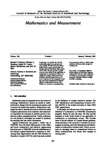
Figure 3. Computational grid showing the orifice-keeper and plume regions.
The computational domain is shown in Fig. 3 and employs 54 by 50 non-uniform, rectangular cells. A time-step of 5 x 10"9 s is employed, which is smaller than the inverse plasma frequency. The simulation
American Institute of Aeronautics and Astronautics
(c)2001 American Institute of Aeronautics & Astronautics or Published with Permission of Author(s) and/or Author(s)' Sponsoring Organization.
AIAA-2001-3795 typically reaches a steady state after about 20,000 iterations and final results are obtained by averaging over a further 20,000 iterations. Results and Discussion
The operating parameters of the test article are very different than for an ordinary discharge. The cathode to anode voltage, Vck, is less than 35V. Vck depends on the cathode temperature, flow rate, Ick (which influences cathode temperature), and presumably the condition of the dispenser, size of the orifice and other details of the geometry. At high temperature, such as normally obtained upon startup but prior to shutdown of the cathode heater, Vck can be substantially below 20V. The time dependence of test chamber pressure following a change in cathode operating point has not been previously investigated. The test chamber pressure is proportional to the mass flow rate exhausted by the cathode. The flow rate requires a substantial period of time to return to its equilibrium value, following a change in the keeper current. A change in heater current during the startup cycle requires a similar period of time to return to equilibrium. Figure 4 indicates the background pressure in the test chamber as a function of time following an increase of heater current from 1.7 to 2.0 A. The change is gradual throughout, as may be expected from a thermal phenomenon. The chamber pressure initially falls, presumably because the pressure elevation in the xenon gas behind the nozzle is constrained by the pressure in the cold gas reservoir of the supply line. Since the flow metering system supplies a constant flow into the reservoir, eventually the nozzle backing pressure will rise enough to again produce the original nozzle flow rate prior to the perturbation. If the nozzle backing pressure changes slowly compared to the temperature (due to the large size of the reservoir and low flow rate), an initial T"1/2 dependence in the test chamber pressure would be expected, where T is the stagnation temperature.20 When the keeper discharge switches on or off, the change in the background pressure of the vacuum chamber is large and immediate. This is followed by a slow return to the original level, on a time scale similar to that of Fig. 4. This observation suggests that the initial effect is nonthermal, whereas the subsequent drift toward equilibrium and return to the starting chamber pressure is either thermal or determined by the flow rate and rate of change in nozzle backing pressure. Figure 5 indicates the step function in test chamber pressure and subsequent exponential decay that results from abrupt shutdown of the discharge at operating point 5 (OPS, see Table 1). It is likely that this behavior is associated with a flow impedance in the orifice when the discharge is on. Measurements on a T6
hollow cathode have revealed a complex variation of its back pressure with current and flow levels.7 Other measurements on similar hollow cathode systems indicated that plasma and keeper potentials were similar in the gap between keeper and cathode orifice.10 A substantial voltage difference between plasma on opposite sides of the cathode orifice may therefore exist. The potential would then presumably have a large gradient in the vicinity of the outlet, and efficient ionization of the gas would occur in this region. The formation and upstream migration of ionized xenon at the outlet will tend to reduce the net transport rate of neutral xenon in the downstream direction. The electric field will establish an upstream drift velocity for ionized xenon inside the orifice. In sufficient numbers and with high drift velocity, the upstream transport on discharge turn-on could reduce the net downstream transport until the back pressure rises sufficiently far to re-establish the net downstream flow rate at the original level. In addition, the ions will collisionally transfer momentum in the upstream direction to neutral xenon. For this mechanism to be effective it is necessary to have high fractional ionization. An orifice current density > 5xl03 A/cm2 at the flow rate of about 0.3 g/cm2s corresponds to an approximate electron efflux to atomic particle efflux ratio of > 20, and a sizable emission of doubly charged ions has been observed,5 suggesting that a high ionization fraction is generated in some region of the device. A mechanism involving the jxB force and a z pinch effect may alternatively, or in addition, serve to elevate the back pressure.7 The z pinch mechanism presumes a runaway increase in the jxB force below some critical flow rate or orifice pressure.
10
15
20
25
Elapsed Time (minutes)
Figure 4. Test chamber pressure following an increase in cathode heater power from 1.7 to 2.0 Ampere (keeper supply off).
As a result of the flow impedance already discussed, the nozzle backing pressure builds up to a
American Institute of Aeronautics and Astronautics
(c)2001 American Institute of Aeronautics & Astronautics or Published with Permission of Author(s) and/or Author(s)' Sponsoring Organization.
AIAA-2001-3795 higher level in order to regain the flow rate through the nozzle as set by the flow metering system. The data of Fig. 5 suggest that the nozzle backing pressure during cathode operation was more than 4 times higher than under cold flow conditions. Upon startup, the vacuum chamber pressure drops immediately and is slowly regained over a similar time scale. 7 6 — —
o 5
ion gauge, OPS after shutdown ion gauge for OPS, less baseline 3-parameter exponential fit 2-parameter exponential fit ion gauge, OP6 shutdown ion gauge, OPS before shutdown
8 3
2 2
0 I— -100
100
200
300
400
500
600
Elapsed Time (seconds)
Figure 5. Test chamber pressure following shutdown of the keeper power supply.
In our previous study of the T5 hollow cathode,5 the mass spectrometer indicated a rapid initial rise in both Xe2+ and Xe+ flux with increasing keeper current. However, above Ick ~ 1.3 A the Xe+ flux decreased substantially whereas Xe2+ continued to increase rapidly. Above Ick « 2.0 A the quartic relation describing Xe2+ flux also failed. The cathode was not operated above 2.3 A due to concerns about the high power level. While Xe3* may have been detected at the highest Ick levels, any signal present was very weak. The Saha equation is
indication that Te = 1-2 eV may be sufficient to produce the level of ionization observed. The ion current collected by the RPA is shown in Fig. 6 as a function of keeper current at F - 0.10 mg/s, for two angles with respect to the hollow cathode. The data show a sharp dependence on Ick at low levels, but the collected current is nearly constant at Ick = 1.4 A and above. This observation is consistent with the approach to a fully ionized condition, as previously hypothesized.5 A first asymptote may be reached at ~ 1.5A. The RPA current then appears to slowly rise for Ick > 1.8A. This behavior is not inconsistent with step ionization. Conversion from predominantly Xe+ to Xe2+ could account for the apparently increasing RPA current at Ick « 2.0A. The absence of well-defined step behavior may result from a non-uniform distribution of ionization fraction in the gas. The angular dependence of the ion current at several operating points is shown in Fig. 7 (see Table 1). The low-flow case corresponds to the highest peak. The angular full-width-half-maximum (FWHM) of that data is also less. Visual observation of the hollow cathode indicated a more extended plume, about 3 cm long. The divergence therefore is pressure dependent and also possibly influenced by keeper potential, which was 33.8 V for the low-flow case and 26 V in the highflow case. 6000
5000
< 4000
t 3000 O CL 2000
• A •
3/2 1000
-INlkT
2
( h
)
15^3/2 -IN/kT
1
e
u'N cm.3 .
phi = 0 degrees phi = 0, second set phi = 15 degrees
0
1
(9)
where nN-i and n^ are the densities of xenon ions with N-l and N electrons, respectively, the u1 are their partition functions and IN is their ground state energy difference. From this expression can be obtained the electron temperature corresponding to a given charge state fraction under local thermodynamic equilibrium (LTE) conditions. For the case of Xe2+/Xe+, the population ratio at n«Fl015 cm"3 is 17% with kT=1.2 eV and 74% with kT=1.3 eV. At kT=2.0 eV the dominant species is predicted to be Xe3+. LTE is a good assumption in this case only for more closely spaced energy levels, but the exercise does provide an
2
3
lck (Ampere)
Figure 6. Dependence of normal-incidence RPA current on keeper current.
Also shown is data for a medium-flow case, with higher keeper current (operating point 6). Here the divergence is lowest despite a keeper potential of just 28 V, consistent with the possible operation of a jxB pinch effect. In Fig. 8, computed angular profiles for the currents of Xe+ and Xe2+ ions are compared with experimental data. The computations are for OP1 while
American Institute of Aeronautics and Astronautics
(c)2001 American Institute of Aeronautics & Astronautics or Published with Permission of Author(s) and/or Author(s)' Sponsoring Organization.
AIAA-2001-3795 the data are for OP4 (the only difference is a 7% higher keeper current for OP4). The agreement between the measured data and model predictions is quite good. This fact indicates that there are not significant charge separation effects in the plume flow. Ion current emitted from the T5 hollow cathode was collected as a function of the RPA repeller voltage. The data of Fig. 9 were obtained for several operating points (see Table 1) and at several angles, (|> = 0°, 15° and ~ 74° between the RPA normal and the hollow cathode plume axis.
could be similar to Vck, typically 25-30 V. The majority of ions observed at = 74° are probably formed near the keeper aperture. The quantity AI/AVr, plotted in Fig. 10, approximates the ion energy distribution. For $ = 74° the distribution peaks were found to be at 19 and 23 eV for OP1 and OP2, respectively, consistent with the relative magnitudes of Vck. The major difference between OP1 and OP2 is flow rate. The ion flux at = 74° was approximately 10000
12000
9000-
- Phi = 0, OP3
8000
- Phi = 0, OPS
-Phi = 74deg.,OP1
10000
7000
~ 8000 ^ c 6000
-Phi = 15deg., OP1 - Phi = 0, Vcb = +50V
6000 5000 4000
O
4000
3000 2000
2000
1000 0
40
-40
-20
0
20
40
60
80
100
Retarding Potential, Vr
Angle, (degrees)
Figure 7. Angular distribution of ion efflux for several operating points.
Figure 9. RPA current obtained as a function of repeller voltage at various operating points.
proportional to flow rate for these operating points. For the low pressure case the distribution goes to zero at Vr = 31, about the value of Vck. The high pressure case
10'ET
Xe+2 (data) Xe '(data) X9+2 (model) Xe * (model)
10°
10
*E
Phi = 0, OP3 Phi = 0, OPS 15deg.,OP1 Phi = 74 deg.. OP1 Phi = 0LVcb = +50V
1CT3
1Q-4
30
O(deg)
60
90
Figure 8. Comparison between model and experimental results for Xe* and Xe2+ currents.
When viewing the hollow cathode at large Xe(fast) + Xe2+ (slow) Xe3+ (fast) + Xe(slow) -> Xe(fast) + Xe3+ (slow)
0.40 0.35 0.30
— —— — o
Xe2+/Xe+ ratio 3-P Gaussian fit Double exponential fit Xe+
4.0e-7
0.25 -10
0
will occur at high rates, particularly in the early stages of the expansion. Non-symmetric charge exchange processes such as
10
Angle 0 (degrees)
Xe2+ + Xe+ -> Xe+ + Xe2+
Figure 15. Xe+ flux and uncorrected Xe2+:Xe+ ratio as a function of 0 for OP6, from QMS data.
to a quadratic dependence. The Xe+ data is more sensitive to the equilibrium of the hollow cathode following a change of setpoint. The Xe2+:Xe+ ratio was observed to be significantly higher at the lowest flow rates, and less than was previously observed for a given keeper current. Erosion of the cathode orifice is a possible explanation, since this would reduce the current density. This hypothesis is supported by the fact that the discharge voltage tends to increase with
are estimated to be slower typically by an order of magnitude, based on the limited data that are available.21'22 Neutral density is >lx!014 cm"3 throughout the cathode-keeper gap, resulting in mmscale mean free paths for the fastest charge exchange processes. Non-symmetric reactions will produce energetic ions with lowered charge state, but may not
American Institute of Aeronautics and Astronautics
(c)2001 American Institute of Aeronautics & Astronautics or Published with Permission of Author(s) and/or Author(s)' Sponsoring Organization.
AIAA-2001-3795 determining the validity of proposed mechanisms for high energy ion production in the hollow cathode plume. In the potential hill model, energy distributions will depend strongly on charge state, whereas the gas dynamic model predicts energy distributions to be similar for all ions.8'25'26
proceed at sufficient rates to cause the broadening observed in Fig. 11. The process of recombination is also capable of producing lower charge states with enhanced kinetic energy. Many highly charged ions readily undergo a process of dielectronic recombination, the inverse of autoionization. The ion captures a free electron into an upper bound level when that electron loses an appropriate amount of energy by scattering with and exciting an already bound electron to produce a metastable state of the ion. For recombination to be completed, the excess energy must be subsequently lost through a radiative transition or collision before autoionization occurs. Recombination is typically a slow process but can be relatively fast for multiplycharged heavy atoms like xenon, strongly affecting ionization equilibria at high temperature. In addition, three body recombination rates involving two electrons and an ion can be significant for r^ > 1014 cm"3 and low Te(a3-Te-9/2). A gas-discharge laser using recombination pumping has been constructed that operates on transitions of Xe IV at similar gas and current density as exist near the hollow cathode orifice.23 Recombination of Xe III through Xe V occurred on the jis time scale at n« ~ 1015 cm"3, with rate °c z3.23 Many of the relevant charge transfer and recombination rates have not been measured, and therefore the role of these processes cannot yet be worked out in detail. To explain observed peak energies and widths, an accelerating potential drop is required in conjunction with the charge-lowering process. The modeling result of Fig. 12 has a potential drop of about 7 V in the several mm between nozzle exit plane and keeper. The magnitude of this drop is sensitive to operating point and can be considerably greater. A Xe3+ ion traversing a 10V drop will acquire 30 eV of kinetic energy, in the absence of collisions. If it is then converted to Xe+ at a plasma potential of 30V, this ion will possess 60 eV of kinetic energy when it reaches a ground plane. The location of charge state conversion obviously will affect the final energy. Collisional scattering effects may cause additional broadening of the energy distribution. The density of charged and neutral particles in the cathode-keeper gap is substantially higher than exists in the plume of a typical ion engine or even Hall thruster. Yet, recent data appear to indicate the operation of rapid charge state conversion mechanisms in Hall thruster plumes.24 Hollow cathode plume measurements using a high resolution electrostatic analyzer also sometimes exhibit peaks at integer and half-integer multiples of a lower energy peak, possibly a signature for charge state conversion.4 Accurate measurement of the energy distributions for the various charge states would be valuable for
Feasibility as Ion Thruster The data are consistent with a near-unity fractional ionization of xenon near the cathode orifice, at the higher Ick operating points. The integrated current collection increased with reduced cathode flow rate and with increasing keeper voltage and current.
6E-11 -
•Xe+ 5E-11 -
A Xe2+/Xe+ Uncorrected Ratio
* \ 4E-11 ! ^
; 3E-11 i » 2E-11
0.8
1
1.2
1.4
Keeper Current (Ampere)
Figure 16. Ion flux level and charge ratio dependence on cathode keeper current. 1.80E+02 1.60E+02
• Total QMS Current, theta = 0 ° RPA Current, phi = 74 deg.
—Linear fit £
1.40E+02
^
1.20E+02
~
1.00E+02
g
8.00E+01
| 6.00E+01 O
4.00E+01
2.00E+01 O.OOE+00 O.OOE+00
2.00E-02
4.00E-02
6.00E-02
8.00E-02
1.00E-01
1.20E-01
Flow Rate (mg/s)
Figure 17. Collected current levels as a function of hollow cathode flow rate.
The propellant utilization efficiency of ion engines and Hall thrusters is typically above 80%. To be useful as a low power ion thruster, utilization does
10 American Institute of Aeronautics and Astronautics
(c)2001 American Institute of Aeronautics & Astronautics or Published with Permission of Author(s) and/or Author(s)' Sponsoring Organization.
AIAA-2001-3795 not necessarily have to be as high. A much lower figure may serve as a suitable threshold for development of a practical device. At the lowest flow rates investigated in this study, 0.03 mg/s, the equivalent current level of 100% singly ionized xenon is about 20 mA. An estimate of the total current flux at operating point 2, obtained by integrating the ion flux over the angular distribution, indicates that about 2 mA of current is already being exhausted. Without any attempt to improve the efficiency of the extraction process, the mass utilization is already about 10% for this operating point. Some thought has been previously given to hollow cathode use as an ion source.27"30 These devices have been quite different from the one described here, and not intended for space propulsion. In one case, more than 20 mA was emitted through an aperture in the cathode, using an extraction electrode at -0.9 kV and an argon flow rate of 0.1 mg/s.29 This corresponds to a propellant mass utilization of about 35%. Due to the large surface area and geometry of the insert, however, the device in the present study is not well suited for the extraction of ions through the cathode.
The hollow cathode does not necessarily require a neutralize^ however. With a proper extraction electrode placed downstream from the keeper the available current might potentially be increased. This would be beneficial to increase the thrust and efficiency of the device as well. 20 mA of extracted current at 1 keV corresponds to about 20 W of beam power and 40% efficiency if 30 W is expended in the discharge. Fig. 18 shows the results obtained when an extractor electrode was positioned at d = 3 mm downstream from the keeper and fixed at ground potential while the cathode body voltage was varied. A modest increase in far-field ion flux was obtained ((^O) with Vcb elevated to 65V. Since !