Point-Based Modeling from a Single Image Pere-Pau V´azquez†, Jordi Marco†, and Mateu Sbert‡ †Dept. LSI - Universitat Polit`ecnica de Catalunya, Spain {ppau|jmarco}@lsi.upc.es ‡IIiA, Universitat de Girona, Spain
[email protected]
Abstract. The complexity of virtual environments has grown spectacularly over the recent years, mainly thanks to the use of the currently cheap high performance graphics cards. As the graphics cards improve the performance and the geometry complexity grows, many of the objects present in the scene only project to a few pixels on the screen. This represents a waste in computing effort for the transforming and clipping of maybe a lot of polygons that could be substituted by a simple point or a small set of points. Recently, efficient rendering algorithms for point models have been proposed. However, little attention has been focused on building a point-based modeler, using the advantages that such a representation can provide. In this paper we present a modeler that can generate 3D geometry from an image, completely built on points. It takes as input an image and creates a point-based representation from it. Then, a set of operators allow to modify the geometry in order to produce 3D geometry from the image. With our system it is possible to generate in short time complex geometries that would be difficult to model with a polygon-based modeler.
1
Introduction
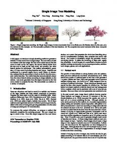
The complexity of virtual environments has grown spectacularly over the recent years, mainly thanks to the, now affordable, high performance graphics cards. These highly complex models are made of objects that usually cover only a few, or Fig. 1. The famous Dal´ı bread on the wall even fractions of, pixels on the screen. of the museum (left and right) and a 3D Polygon-based systems are advan- modification of it (center). tageous for the modeling of large objects, but, for small ones, many resources are wasted by transforming and clipping geometry which is either invisible, or very small when projected to the screen. This has led to the investigation of alternatives to pure polygon-based rendering in recent research. An interesting alternative is point-based rendering [1–5]. In this paper we present a modeler that takes advantage of a point-based representation to easily build 3D geometry starting from a real (or synthetic)
image. It takes as input an image, builds a point-based model, and then offers a set of operators that allow the user to easily manipulate the point-based geometry and create very interesting modifications of the geometry and obtain a 3D model. Our system does not pretend to reproduce exactly a real object but offers a means to create a realistic object starting from a real image. This allows to create models of both small and large objects in several minutes. An example of this is shown in Figure 1. Figure 1-left shows a photograph of one of the famous bread pieces that are part of the wall of the Salvador Dal´ı’s museum in Figueres. Figure 1-center shows how it looks after a manipulation the user carried out in only two minutes and five seconds. In Figure 1-right we can see the photograph as seen from the same angle. The rest of the paper is organized as follows: Section 2 surveys related work. Section 3 gives an overview of our system and the user interaction method. In Section 4 we describe the basic operators available and show some examples. Finally, Section 5 concludes our work pointing to some lines of future research.
2
Previous Work
Modeling complex realistic objects is a difficult and time consuming process. Though there are many systems for modeling the real world from images, reconstruction of complex and detailed geometry is still cumbersome. Reconstructing 3D geometry from one, two, or more photos is a fundamental problem that has received extensive attention in computer vision [6, 7]. Although the best results are obtained in controlled conditions, a good and complete solution has not been found yet. Another possibility is the use of expensive scanning devices, however this presents serious problems for large objects such as buildings and statues [8]. Image-Based systems replace partially or completely the geometry with images, the reconstruction techniques are similar or borrowed from Computer Vision and therefore suffer from the same drawbacks. Some examples are [9, 11]. As Poulin et al. [10] argue, the user intervention is very important in order to improve the quality of the results of a reconstruction. They present an interactive modeling system that extracts 3D objects from photographs, using a point-based representation that allows the user to intervene and improve the obtained model. However, they not allow a direct intervention of the user on the geometry. In this sense, our work can be seen as complementary to theirs. Several approaches exist on building point based representations from a synthetic geometry [2, 11–14, 5], where the problem of sampling is also focused.
3
Overview of the system
Our system consists in two parts, a rendering tool, which shows the results of the modifications to geometry, and a manipulation tool, that presents the initial image and allows model the geometry using the provided operators. Initially, the image is read and for each position a 3D point (with Z = 0) is created. In order not to lose resolution, both the rendering and the manipulation tools open
windows of a size equal to the size of the image, and the point model has a point for every pixel of the image. The rendering tool is allows the camera movements needed inspect the changes made to the model, that is, rotation and translation. We have decided to render the objects in orthographic view in order to avoid the perspective projection to hide details in the comparison of the generated model with the initial image. Consequently, the rendering window and the manipulation one start showing the same image. The rendering window also serves to show how the next operator will affect the resulting model (actually it shows the region that will be affected if set as modifiable) in order to aid the user to accurately predict the final changes. The manipulation tool shows the image that will be modified and allows to select the regions that are going to be changed, together with the operators that will be applied. Our system allows for modifications on a single direction the Z axis. This is due to the fact that, as we are working mainly with real photographs, what there is lacking is the Z coordinate, which is what we want to somehow build or imitate. We do not want to build the 3D geometry represented in the image according to the exact measures, but, as it will be seen, our system can be extended to work with real measures, we only need to know, as a reference, the measure of some feature appearing in the image. No special knowledge of computer graphics or 3D geometry is required to work with the modeler. The user first selects a set of regions and then sets the operator to be applied to each region. We describe now the main issues. Region Selection: There are two kind of regions, a) main region, and b) secondary regions. All the points in the main region are transformed in the same way: their Z value is changed according to the user’s definition. Secondary regions are changed according to the operator applied. A selection may be of three kinds: a) A set of (one or more) points, b) a single line, and c) a polygon. Regions consisting of single points are used for the main region as they permit very powerful manipulations to geometry, as we will see soon. In order to allow for continuous regions selections, our selection method first tests if the point we want to add to our region does currently form part of a previously defined region, if the point passes this test, it also checks if there is a previously selected region in its near environment (4 o 5 pixels around), if so, the selected point is moved next to the close region, as we assume that two regions that are very close are going to be modified together (maybe with different operators) and we do not want discontinuities (points still lying on the Z plane) on the result. We also allow to select a region that contains another region, which is very useful to define conic or spherical transformations.
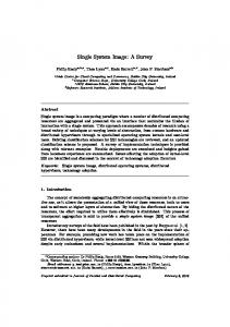
Z = Zinc − m · dist Operators: When the regions are already selected, we define an operator for each one (main region is always modified using the stair operator). The modification consists in chang- Z inc Z ing the Z value of the points inside the main region and the Z values of the points belonging to the secondary regions. The main region is assigned a constant value. Points inside secdist ondary regions are modified according to the distance to the Fig. 2. Lineal closest point of the main region. For a linear transformation, operator. the new Z value of a point will be Z = max(0, Zinc −m·dist), where Zinc is the Z value assigned to the main region, as depicted in Figure 2. Some of the regions (up to 10) can also be selected through a menu, this way it is easy to select regions formed by single points or single lines. Hole filling: Each change in the geometry, may generate holes. Our system uses a hole filling process that is applied to the resulting model. Although we have not dealt with efficiency issues yet, and this is a very costly process, our system is able to work interactively for relatively large images. We have found that there is a delay of some seconds (4 or 5) for the whole process (modification and hole filling) in the case of quite large images (500 × 750 pixels) if the regions to modify are also large.
4
Operators
Differently to Poulin et al. [10], our operators allow to directly modify the 3D geometry. In their framework they offer tools for filling with points (the interactive modeling tool), generating more points using rules, point jittering or merging a neighborhood of points. Our philosophy is totally different, we want tools for the easy generation of shapes on the Z coordinate in order to create objects with realistic appearance. The operators implemented are: stair operator, flatten operator, lineal operator, cosine-based operator, and cape operator. The stair operator performs a constant change on the Z axis. When applied to any region, each point is assigned the Z value determined by the user. In Figure 3 we can see an example of this tool. The image on the left shows the entrance of a house, and on the right we have pulled the wall all around. Note that the stair function has generated a realistic 3D geometry. Only at the left part of the door the Fig. 3. Stair operator. colours of the bricks where not copied when filling holes because the region selection at this point overlapped a little part of the wooden material. The flatten operator restores the points of the selected region to Z = 0 and eliminates the extra points that were added for hole filling during the geometry update. The lineal operator serves to create slopes. The lineal operator modifies the the points of secondary regions using the following equation: Z = max(0, Zinc −
m · dist), where Zinc is the Z value assigned to the main region, dist is the distance to the main region and m is the slope of the linear function. Available values for m are: 0.25, 0.5, 0.75 and 1 to 5. The conic operator, similar to this one, creates a linear modification with a slope determined by the closer point to the main region (Z will be Zinc ) and the farther one (Z will be 0). The cosine-based operators allow to create rounded shapes. These operators allow to modify a region with a curve that is a function of the cosine of the distance, so the points in the secondary regions will have a new Z value following the formula Z = max(0, Zinc − cos(m · dist)) where m has values from 1 to 5 and from 0.5 to 0.9 (with increments of 0.1). We also offer the functions Z = max(0, Zinc − (1/2) cos ·dist) and Fig. 4. Cape operator. Z = max(0, Zinc − (1/3) cos ·dist). To help the user predicting the results, when one of this operations is selected, for the case of a main region consisting in a single point, the prediction of the influence area is shown as a disk in the rendering window. In this case the user may not be able to easily determine which of these functions is adequate. The operator dubbed cape operator, allows to create a spherical shape. It is the counterpart of the the conic operator but with round shape. In Figure 4-right we can see a battery modeled with this operator. The user modified the model in less than 15 seconds.
5
Conclusions and Future Work
In this paper we have presented a system based on a point representation that is able to create very interesting effects in little time. Figure 5-rigth shows two examples where the main region consisted on isolated points and a linear (top) and a cosine-based (bottom) operators were applied. These manipulations Fig. 5. Different operators aponly needed 90 seconds of user intervention. plied on the same image. Some other operators should be useful, for instance texture application over regions, or smoothing surfaces. A symmetry operator that could copy the same image seen from the front to the back, which is straightforward, could be interesting for symmetric objects. Some other extra functions are also possible such as using real measures from a certain part of the image if available, or the ”intelligent scissors” to easily define selections that adapt to the image.
Acknowledgments Partially supported by TIC2001-2416-C03-01 from the Spanish government, and SGR2001-00296 from Catalan government.
References 1. M. Levoy and T. Whitted. The use of points as a display primitive. Technical Report TR 85-022. CS Department, University of North Carolina at Chapel Hill, January 1985. Available from http://www-graphics.stanford.edu/papers/points/. 2. J.P. Grossman and W.J. Dally. Point sample rendering. In George Drettakis and Nelson Max editors, editors, Rendering Techniques’98, pages 181–192. SpringerVerlag, 1998. 3. H. Pfister, M. Zwicker, J. van Baar, and M. Gross. Surface elements as rendering primitives. In Kurt Akeley, editor, SIGGRAPH 2000, Computer Graphics Proceedings, Annual Conference Series, pages 335–342, Los Angeles, July 2000. ACM Press / ACM SIGGRAPH / Addison Wesley Longman. 4. S. Rusinckievicz and M. Levoy. QSplat: A multiresolution point rendering system for large meshes. In K. Akeley, editor, SIGGRAPH 2000, Computer Graphics Proceedings, Annual Conference Series, pages 343–352, Los Angeles, July 2000. ACM Press / ACM SIGGRAPH / Addison Wesley Longman. 5. M. Stamminger and G. Drettakis. Interactive sampling and rendering for complex and procedural geometry. In Rendering Techniques ’01, EG workshop on rendering, pages 151–162, June 2001. 6. S.M. Seitz and C.R. Dyer. Photorealistic scene reconstruction by voxel coloring. In Proc. of the Computer Vision and Pattern Recognition Conference, pages 1067– 1073, 1997. 7. Tom´ aˇs Werner, Tom´ aˇs Pajdla, and Martin Urban. REC3D: Toolbox for 3D Reconstruction from Uncalibrated 2D Views. Technical Report CTU-CMP-1999-4, ˇ Czech Technical University, FEL CVUT, Karlovo n´ amˇest´ı 13, Praha, Czech Republic, December 1999. 8. M. Levoy, K. Pulli, B. Curless, S. Rusinkiewicz, D. Koller, L. Pereira, M. Ginzton, S. Anderson, J. Davis, J. Ginsberg, J. Shade, and D. Fulk. The digital michelangelo project: 3D scanning off large statues. In K. Akeley, editor, SIGGRAPH 2000, Computer Graphics Proceedings, pages 131–144. ACM Press / ACM SIGGRAPH /Addison Wesley Longman, 2000. 9. P.E. Debevec, C.J. Taylor, and J. Malik. Modeling and rendering architecture from photographs: A hybrid geometry- and image-based approach. In Computer Graphics Proceedings (Proc. SIGGRAPH ’ 96), pages 11–20, 1996. 10. Pierre Poulin, Marc Stamminger, Francois Duranleau, Marie-Claude Frasson, and George Drettakis. Interactive point-based modeling of complex objects from images. In Proceedings of Graphics Interface 2003, pages 11–20, June 2003. 11. L. McMillan and G. Bishop. Plenoptic modeling: An image-based rendering system. Proc. of SIGGRAPH 95, pages 39–46, August 1995. 12. D. Lischinski and A. Rappoport. Image-based rendering for non-diffuse synthetic scenes. In George Drettakis and Nelson Max editors, editors, Rendering Techniques’98, pages 301–314, 1998. 13. S. Fleishman, D. Cohen-Or, and D. Lischinski. Automatic camera placement for image-based modeling. Computer Graphics Forum, 19(2):101–110, Jun 2000. azquez, M.Feixas, M.Sbert, and W.Heidrich. Automatic view selection us14. P.-P. V´ ing viewpoint entropy and its application to image-based modeling. Computer Graphics Forum, 22(4):689–700, Dec 2003.