goal of previously cited point-based techniques is to de- crease the number ... and triangle have the same average area. ... with ¯P the centroïde of Pi. The point ...
Eurographics Workshop on Natural Phenomena (2005) E. Galin, P. Poulin (Editors)
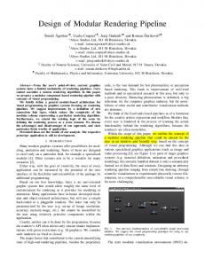
Point-based rendering of trees Guillaume Gilet†
Alexandre Meyer‡
Fabrice Neyret
GRAVIR lab (IMAG - INRIA), Grenoble, France
Abstract The goal of this paper is the interactive and realistic rendering of 3D trees covering a landscape. The landscape is composed by instantiating one or more block of vegetation on the terrain. A block of vegetation is composed by a single or a compact group of trees. For these blocks of vegetation, we propose a new representation based on triangle+point primitives organized into a regular spatial structure (grid). This structure is defined onto easily adapt the level of details (LOD) of each subpart (cell) of the vegetation element. During the rendering process, we determine a global level of details for each block of vegetation. Then, we refine it for each cell according to the following heuristic: leaves or branches on the rear of tree or inside the forest are statistically less visible than front ones and then can be rendered coarsely. As a result, our method greatly decrease the number of rendered primitives by preserving realism. This allows rendering of large landscape in interactive time, for a camera far away until inside. Categories and Subject Descriptors (according to ACM CCS): I.3.3 [Computer Graphics]: Display algorithms
1. Introduction Trees and forests covering hills appear to be a strange material: while the vegetable cover looks like a quasi-continuous surface, one can also recognize individual branches or trees, and sometimes one can see deep inside. The volumetric nature of the forest ‘matter’ is especially obvious when the viewer moves, due to omnipresent parallax and visibility effects. There is far too much foliage data to expect a direct real-time rendering of the leaves (to say nothing of aliasing), and classical mesh decimation does not apply to sparse data. Despite this complexity, classical painters manage to reproduce realistic images of forest [Cor]. They first draw large background branches or trees and then improve the front by drawing fine and precise elements like branches or leaves. Applications requiring the real-time rendering of natural scenes — e.g., flight simulators, video games or outdoor architectural project — are of such importance that early solutions had to be found to get some sort of forest populating
† currently at LSIIT Lab (UMR 7005), Strasbourg, France. ‡ currently at LIRIS Lab (UMR 5205), Lyon, France. c The Eurographics Association 2005.
landscapes: various alternate representations have been introduced to mimic trees and are still used nowadays. Our purpose is to represent and render large number of trees in interactive time. Our method is based on a triangle+point representation with a level of details (LOD) which is non-uniform inside a given element of vegetation, as shown on Figure 2. In each subpart, the choice of LOD is driven by visibility, aiming at reproducing the painter scheme: coarse elements on the rear and precise ones on the front. 2. Previous work In this section, we review alternate techniques allowing the real-time or interactive rendering of trees and forest. Image based: Trees elements like branches or bough are composed by many small elements. An image has the good property to represent very complex objects efficiently with one single primitive. Thus, it is natural that image-based rendering approaches were adapted to trees with various optimization to solve classical IBR issues: • Billboards are the most common tool for realtime rendering of forests. Thanks to their low cost, they are still considered as the best choice in many recent industrial simu-
G. Gilet & A. Meyer & F. Neyret / Point-based rendering of trees
•
•
•
•
lators. They are used in two different ways: classical billboards are single images that always face the camera (possibly with an axis constrained to be vertical) while cross billboards consist of two to four regular textured quads crossing each other. Hierarchical billboards or simplified textured trees: the idea is to build manually or using dedicated tools an extremely simplified tree with a few dozen to a few hundred polygons approximating the foliage distribution. Hierarchical Precomputed Multi-Layer Z-Buffers [Max96, MDK99]. The idea is to combine a hierarchical model with multi-Layered Depth Images [SGHS98]. Hierarchical Bidirectional Texture Function: One way to avoid the obvious artifact of cross billboards at grazing angles is to fade the billboards that are not facing the camera enough. The same idea can be used with a whole set of images taken from various view angles [MNP01]. Volumetric textures: The volumetric textures approach consists of mapping a 3D layer on a surface using a 3D data set as texture pattern. This is especially adapted to a layer of continuous vegetation covering a landscape. It was first introduced in ray-tracing [KK89, Ney98] and later adapted to hardware rendering [MN98] using stack of textured slices. Decaudin et al. in [DN04] specifically adapt it to forest.
Point-based: In recent years, it has been shown in [MZG01, PZvBG00] that point-based rendering is a very efficient means for the rendering of any complex geometry, helped by the efficient graphics hardware capacity to treat it. The idea is based on the observation that in increasingly complex scenes triangles become smaller than a single pixel. In this case, triangle based scan-line rendering wastes time in superfluous sub-pixel computation. Moreover, points can be merged easily. So the degree of detail can be fluently adapted by adding or removing single points. Weber et al. [WP95] and Deussen et al. [DCSD02] present two models to render trees in real-time with a combination of polygons and points-lines representation. In the context of level of details, they also introduce the idea that best visual results can be achieved if the plants are not uniformly reduced. To allow a large number of rendered trees, both rendering algorithms progressively reinterpret the tree according to the distance: branch meshes are transformed onto lines and leaf polygons onto points. At longer ranges, some individual branches and leaves will simply disappear in [WP95]. This could lead to important visual artefact. Thus, Deussen et al. merge disappearing elements in larger primitives (points or lines) to better convey the shape in distant views. To select which parts of the trees have to disappear, Weber et al. use an automatic criteria on size whereas Deussen et al. ask user to make the selection during the modeling process. In the gone scope of reducing the number of primitives, an interesting idea is to keep only the visible ones. Guen-
nebaud et al. in [GP03, GBP04] take advantage of temporal coherency in hardware accelerated accurate point selection algorithm. Their method is based on a multi-pass algorithm. The initialization part consists of a first rendering which gives the list of visible points; all hidden points being discarded by the depth test. For each frame, this list is updated by rendering potentially visible points which are given by a hierarchical and multi-resolution data structure (an octree more largely describe in [GP03]). The list of visible points is efficiently managed on the GPU. Their technique is not specific to vegetation. But a forest, because of the specific visibility configuration, is a really good frame to apply it.
3. Motivation and overview Because of the flexibility of point-based approaches regarding levels of details (LOD) computation in comparison to image primitive, we oriented our work to point. The main goal of previously cited point-based techniques is to decrease the number of rendered primitives without loosing visual important characteristics. Guennebaud et al. in [GBP04] based his selection on the visibility. But even if a part of an object is visible, it could be interesting to adapt its LOD. Deussen et al. in [DCSD02] ask an user to define the important part of plants in order to orient the simplification toward less sensitive parts. In an other context, Reeves et al. in [Ree83, RB85] compute efficiently self-shadowing by doing the assumption a primitive inside a tree has statistically less chance to see the light. Our idea comes from the crossing of these roads. We search to automatically increase the degree of simplification on less visible part as shown on Figure 2). To define the landscape, we instantiate one or more blocks of vegetation which are composed of a single tree or a compact group of trees. To tackle the visibility issue, we propose to organize block primitives in a regular structure describe in Section 4. Then, during the rendering process described in Section 5, we adapt the LOD of each subpart of the structure according to the heuristic previously mentioned. Finally, in Section 6 we present results and we conclude in Section 7.
4. Our representation As input of our method, there is an unorganized soup of polygons describing a block of vegetation. To define a block, the user put polygonal trees generated by software like [CIR, os] in a small area. During the rendering we will use the polygonal representation in combination with a hierarchical point-based representation. The point-based representation consists of a base point set (obtained by converting the triangles) and sets of coarser points. The triangle set plus these point sets form our hierarchy of LOD. In this section, we describe the different steps to built our data structure. c The Eurographics Association 2005.
G. Gilet & A. Meyer & F. Neyret / Point-based rendering of trees
Figure 1: (a) Each point falls into a cell of a regular grid. (b) In each cell, a hierarchical clustering algorithm computes a binary tree where each node defines an average point of the sub-tree. (c) The points from the binary tree are size-sorted to be efficiently managed by the GPU as in [DVS03].
grid ranges from 4 × 4 × 4 for a single tree to 4 × 16 × 16 for a group of trees‡ . Now, we have to define a multi-resolution scheme for each cell.
4.2. Hierarchical clustering
Figure 2: A block of vegetation can be composed of a single tree or of group of compact trees. These blocks are instantiate on the landscape. Our method is based on a triangle+point representation. Our goal is to adapt the precision of each sub-part of a block according his view dependent position: front parts should be finer, rear parts should be coarser.
4.1. Regular grid We first convert each polygon to triangles, which are themselves converted into points. In each cell, we will store the triangles set as well as the corresponding point set. Each point is characterized by a position, a color, a radius and a normal. The point location is defined as the gravity center of the associate triangle. The radius is defined such that point and triangle have the same average area. The normal is the one of the triangle. The color is the integral of the texture covering the triangle.
In a cell, the triangle set defines the finest LOD. The base point set is the next level. The coarser LOD are obtained by merging points in the point set. For this task, we use a hierarchical clustering method based on principal component analysis. Note that any clustering scheme could have been used, see [PGK02] for more details. Let name Pi the point set in a cell i. We compute the set of clusters recursively by splitting Pi using a binary space partition. We compute the covariance matrix: T Pi1 − P¯ Pi1 − P¯ ... ... ¯ ¯ C= (1) Pi j − P · Pi j − P , i j ∈ Pi ... ... Pin − P¯ Pin − P¯ with P¯ the centroïde of Pi . The point set Pi is recursively split by the plane defined by the centroïd P¯ and the eigenvectors of the covariance matrix. I.e., the point cloud is always split along the direction of greatest variation. This subdivision process is iterated until the number of point in the cluster is lesser than a threshold. In practice, our threshold is around 5 which is a good tradeoff between memory consumption and realism. As shown in Figure 1 (b), hierarchical clustering builds a binary tree.
To be able to manage independently each part of a block, we subdivide the space into a regular grid (see Figure 1 (a)). A regular structure has the main advantage to allow the efficient access to data at rendering time. We put each primitive (triangles† and points) into cells. In practice, the size of our
To complete the LOD, we have to compute coarse points associated to each node of the binary tree. The purpose of this coarse point is to average the corresponding sub-tree. Its position are the average position of his two children l and
† Note that triangles falling in more than one cell are affected to an arbitrary one.
‡ If the block is defined by a large number of trees it can be interesting to increase this size.
c The Eurographics Association 2005.
G. Gilet & A. Meyer & F. Neyret / Point-based rendering of trees
r weighted by their size. Its normal and color are computed similarly. We compute the average radius R as: R=
2 (Rm + α(RM − Rm )) Π
where RM = Rl +Rr and Rm = 21 (Rl +Rr ) corresponds to extremal configurations, α = |Nl N˙ r | modulates them according to the relative orientations, and Π2 is a normalization factor averaging all the possible view directions. 4.3. Hardware storage and sequentialization Since our goal is the interactive rendering, we have adapt our structure according to the GPU constraints. Rendering recursively a binary tree would not be suited to sequential processing by the GPU. Vertex array is the natural organization for the GPU. Dachsbacher et al. [DVS03] sequentialize a binary tree to a vertex array and replace the recursive rendering procedure by a sequential loop over the array. They sort nodes of the binary tree according to an error criteria. We apply a similar scheme to our case: we sort the whole set of points defined by the binary tree according to their size (see Figure 1 (c)). We choose this criteria because it will allow us to select points by comparison to a target pixel size. It makes sense for a user to select the tradeoff between performance and quality by tuning the target pixel threshold. We also organize the triangle set in the same way.
smaller, the next LOD must be used. Note that this criteria also prevents the aliasing artifacts which would occur if drawing clouds of primitives smaller than pixels. Moreover, this size can be larger than a pixel: this allows the user to control the frame rate, or to keep the frame rate constant if required. Basically, sm and sM define the range of acceptable projected primitive size on screen space. All rendered points will have a projected size between sm and sM , and all rendered triangles will have a projected size upper than sM . To select the primitives to be drawn, we need to determine the corresponding criteria Sm and SM in world coordinate (using the distance from the camera to the cell and the camera characteristic). What we need is the min and max indices of the range in the points vertex array plus the min index of the range in the triangles vertex array. Since primitives are sorted by size it is obvious to determine them using a dichotomy search into a copy of the arrays in main memory. The ranges are illustrated on Figure 3 (b).
Note that we could also have used a unique array for the whole grid instead of one per cell but it occurs that this not efficient for hardware performance reason. 5. Rendering and level of detail This section describes how we determine the LOD to apply at run time. More precisely, we have to determine for each cell which subset of the triangles and subset of points have to be used. I.e. we have to determine the range to display in the two vertex arrays. These choices are guided by two criteria: the projected size of the block on the screen (corresponding to its distance) and the view dependent order of the cells within the block (to take advantage of the masking, since a block is assumed to contain compact vegetation). 5.1. Rendering of a cell For close points of view, rendering triangle is still the best option. Drawing a triangle is less costly than drawing points as long as the triangle’s projected area is above an certain threshold. So, it is reasonable to state that the primitive point is a valid choice if its projected size is smaller than a threshold sM otherwise triangle has to be used. sM is the maximum projected surface (measured in pixels) allowed for the point representation. I.e., it defines the limit between point and triangle. We introduce a second threshold: sm which is the minimum size of a projected point. I.e. if a primitive is
Figure 3: Two thresholds min and max define in pixel unit the range of acceptable primitives. For a given cell (b), we deduce the range (resp. the lower boundary) of points (resp. triangles) which have to be rendered. Rendered points and triangles have grey background on the arrays. According to the position of the cell in the grid, we shift the min and max thresholds to lower values (a) for detailed cells and to upper values for coarse cells (c).
c The Eurographics Association 2005.
G. Gilet & A. Meyer & F. Neyret / Point-based rendering of trees
5.2. Level of detail for each cell We can now adapt the precision of the rendering for each cell independently to take advantage of the masking within the block by tuning the two thresholds Sm and SM . This is done by biasing them linearly according to the depth of the cell within the block. We compute the two distances: d1 between the camera and the center of the block and d2 between the camera and the center of the cell i. Then, we define Zi = (d2 −d1 )/R where R is the block size. Zi is a real in the range [-1,1]: from -1 for the nearest cell to 1 for furthest cell. Thus, i i Sm and SM are computed for cell i as follows: i Sm = Sm + k.Zi
(2)
i SM
(3)
= SM + k.Zi
where k is a user constant defining the precision contrast between the front and the back. The bigger k, the more LOD difference between the front and the back of an object (illustrated on Figure 3, top).
and a castanea ' 430k. A few different blocks of vegetation were created, and instantiated multiple times in the scene (under the control of a user defined texture). A block of vegetation composed of one prunus and two picea generates ' 300k points. The GPU memory cost for this block (geometry + point structure) is ' 26Mb which is important. Still, current GPUs allow the storage of several blocks. The good property of point sets is to allow a quasicontinuous simplification. Indeed, with a model of 100k points one can manage to use 100k levels of details. Our representation requires two to three times less points than an uniform simplification (like [PGK02]) as illustrated on Figure 4 for the castanea tree. Images 5 shows our algorithm rendering a landscape made of 200,000 trees. The frame rate varies from 3 fps to 10 fps. For smaller scenes (< 100,000 trees) our frame rate is realtime. Performances are highly hardware and implementation dependent. Still, our thresholds allow the user to choose either a target quality or a target display rate.
5.3. shading Point colors are shaded like triangles using the stored normal. We also account for estimated self-shadows within the block of vegetation in the spirit of [Ree83]. This rely on the same mechanism as for the precision bias: maximal and minimal lighting LM (usually 1) and Lm (equivalent to ambient) are defined equivalently to Sm and SM . Estimated lighting is then L = LM + Zi −1 2 .(LM − lm ).
Figure 4: Left: tree simplified using the [PGK02] hierarchical clustering method (270,000 primitives). Right: tree simplified by our tree specific simplification (140,000 primitives). The original tree has 430,000 triangles. One can see that our scheme produces a good result with less primitives (note that the point of view is not exactly equivalent on both images).
6. Results Our motivation is the real time rendering of a large number of high quality tree models. Our rendering algorithm is implemented on a Pentium 4 2GHz using a GeForce FX 5800 Ultra. For our tests we used three tree models generated using XFrog [os]: a picea ' 21k triangles, a prunus ' 205k c The Eurographics Association 2005.
7. Conclusion Our hybrid triangle+point continuous representation allows us to maintain a constant realism, showing little popping and few aliasing artifact. Our rendering algorithm offers a complete freedom of movement, from the close view of a single tree with all the geometric details to an entire forest. In future work, we would like to introduce transparency to help ensuring the equivalent opacity of hierarchical primitives. We are also interested in introducing animation of the trees by displacing the primitives on the fly according to a wind simulation effect. Furthermore, mapping a texture on larger point primitives could help adding even more details using even less primitives.
G. Gilet & A. Meyer & F. Neyret / Point-based rendering of trees
References [CIR] CIRAD: Centre de coopération Internationale en Recherche Agronomique pour le Développement, AMAP. http://www.cirad.fr/produits/amap/amap.html. [Cor] C OROT J.-B. C.: Realism painter. http://impression.alloilpaint.com/corot/. [DCSD02] D EUSSEN O., C OLDITZ C., S TAMMINGER M., D RETTAKIS G.: Interactive visualization of complex plant ecosystems. In Proceedings of the IEEE Visualization Conference (October 2002), IEEE. [DN04] D ECAUDIN P., N EYRET F.: Rendering forest scenes in real-time. In Eurographics Symposium on Rendering (june 2004), H. W. Jensen A. K., (Ed.). [DVS03]
DACHSBACHER C., VOGELGSANG C., S TAM M.: Sequential point trees. ACM Trans. Graph. 22, 3 (2003), 657–662. MINGER
[GBP04] G UENNEBAUD G., BARTHE L., PAULIN M.: Deferred Splatting. In Computer Graphics Forum (septembre 2004), vol. 23, European Association for Computer Graphics and Blackwell Publishing, pp. 1–11 (To appear). (EG2004 Proceedings). [GP03] G UENNEBAUD G., PAULIN M.: Efficient screen space approach for Hardware Accelerated Surfel Rendering. In Vision, Modeling and Visualization, Munich (19-21 novembre 2003), IEEE Signal Processing Society, pp. 1– 10.
[os] ORGANIC SOFTWARE G.: http://www.xfrogdownloads.com/.
Xfrog.
[PGK02] PAULY M., G ROSS M., KOBBELT L. P.: Efficient simplification of point-sampled surfaces. In Proceedings of the conference on Visualization ’02 (2002), IEEE Computer Society, pp. 163–170. [PZvBG00] P FISTER H., Z WICKER M., VAN BAAR J., G ROSS M.: Surfels: Surface elements as rendering primitives. In SIGGRAPH 2000, Computer Graphics Proceedings (July 2000), Computer Graphics Proceedings, pp. 335–342. [RB85] R EEVES W. T., B LAU R.: Approximate and probabilistic algorithms for shading and rendering structured particle systems. In SIGGRAPH 1985, Computer Graphics Proceedings (July 1985), pp. 313–322. [Ree83] R EEVES W. T.: Particle systems – a technique for modeling a class of fuzzy objects. ACM Trans. Graphics (Apr. 1983), 91–108. [SGHS98] S HADE J., G ORTLER S., H E L., S ZELISKI R.: Layered depth images. In SIGGRAPH 1998, Computer Graphics Proceedings (July 1998), pp. 231–242. [WP95] W EBER J., P ENN J.: Creation and rendering of realistic trees. In SIGGRAPH 1995, Computer Graphics Proceedings (Aug. 1995), pp. 119–128.
[KK89] K AJIYA J., K AY T.: Rendering fur with three dimensional textures. SIGGRAPH 1989, Computer Graphics Proceedings 23, 3 (July 1989), 271–280. [Max96] M AX N.: Hierarchical rendering of trees from precomputed multi-layer Z-buffers. In Eurographics Rendering Workshop 1996 (June 1996), Eurographics, pp. 165–174. ISBN 3-211-82883-4. [MDK99] M AX N., D EUSSEN O., K EATING B.: Hierarchical image-based rendering using texture mapping hardware. In Eurographics Workshop on Rendering ’99 (1999). [MN98] M EYER A., N EYRET F.: Interactive volumetric textures. In Eurographics Workshop on Rendering 1998 (June 1998), pp. 157–168. [MNP01] M EYER A., N EYRET F., P OULIN P.: Interactive rendering of trees with shading and shadows. In Eurographics Workshop on Rendering (Jul 2001). [MZG01] M. Z WICKER H. P FISTER J. V. B., G ROSS M.: Surface splatting. In SIGGRAPH’01, Computer Graphics Proceedings (Aug. 2001). [Ney98] N EYRET F.: Modeling, animating, and rendering complex scenes using volumetric textures. IEEE Transactions on Visualization and Computer Graphics 4, 1 (1998), 55–70. c The Eurographics Association 2005.
G. Gilet & A. Meyer & F. Neyret / Point-based rendering of trees
Figure 5: Landscape scene containing 200,000 trees is rendered at 3 fps to 10 fps on a GeForce FX 5800 Ultra. In this scene a single block was regularly tiled, which creates the regular pattern visible in the bottom image. This could be avoided by mapping different blocks with different orientations, or using aperiodic tiling as in [DN04].
c The Eurographics Association 2005.