Th1-6 POLARIMETRIC CURRENT SENSOR
USING A IN-LINE 22.5 DEGREE FARADAY ROTATOR F. Briffod, L. Thévenaz, P.-A. Nicati, A. Kueng, Ph. Robert EPFL Swiss Federal Institute of Technology, Laboratory of Metrology, CH-1015 Lausanne, Switzerland Tel : (++41 21) 693 76 06 Fax : (++41 21) 693 26 14 E-mail :
[email protected]
Abstract : This paper present a polarimetric fiber optics current sensor using a 22.5 degree Faraday rotator and a Faraday rotation mirror. The objective of this sensor is to be low-cost, high accuracy and easy to manufacture. INTRODUCTION
Fiber optic current sensors have some advantages compared to the classical current transformer. The intrinsic
insulation of the optical fiber is an important improvement for high voltage installations. They show a high bandwidth that makes the observations of harmonics and transients possible and offer a total immunity to stray magnetic fields.
Producing commercial optical current sensors is still challenging and prototypes are developed in three different flavors: bulk, fiber interferometric and fiber polarimetric sensors. Bulk current sensors [4] are made using high Verdet's constant crystals, resulting in an excellent sensitivity, but are subject to alignment and temperature drifts. Optical fibers show a lower Verdet's constant, but increasing the number of turns of fiber wound around the conductor results in an improved sensitivity. The interferometric configuration using a Sagnac interferometer [1] measures the non-reciprocal
phase shift with a high accuracy, but the main reported problem is the high vibration sensitivity. The polarimetric method measures the rotation of a linear polarization [2, 3]. Such sensors require a precise orientation of the analyzer. And as a general feature all fiber sensors are sensitive to the variations of the sensing fiber birefringence.
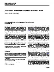
A novel sensor configuration is reported that solves all these problems to a wide extent. In addition, it has the key advantage to require no adjustment on optical elements of any kind and its accuracy is poorly dependent on the optical elements tolerance. This was possible through the introduction of a in-line 22.5 degree Faraday rotator (or 22.5+nx9O degree rotator), as shown in figure 1.
Polarizer Coupler
22.5 degree Faraday rotator
4 configuration A : Mirror configuration B : Faraday rotation mirror
Fig. I : Schematic diagram of the polarimetric current sensor using an in-line 22.5 degree Faraday rotator DESCRIPTION
The optical configuration is simple and based on the back-and-forth propagation through all successive optical
elements, the position of reciprocal and non-reciprocal elements being crucial. First let assume that the electrical current
is zero. The light is linearly polarized by the polarizer and experiences a 22.5 degree rotation through the Faraday
@I OF-1
rotator. The sensing fiber is mechanically twisted and is thus predominantly circularly birefringent [6J, so that the light remains linearly polarized while propagating through the sensing fiber. The light is reflected back by the mirror and keeps its linear polarization. Just before the Faraday rotator on the way back, the polarization has the same orientation as in the forward propagation (configuration A). After the additional 22.5 degree rotation, the polarization is oriented at 45 degree with respect to the polarizer axis.
The linear polarization is therefore just set at the half-transmitting point of the polarizer, so that any small rotation of the polarization — like that caused by an electrical current — results in a linear variation of the transmitted intensity.
When the electrical current I is non-zero, the Faraday rotation p(t) due to the electrical current is after a back-andforth propagation through the sensing fiber:
p(t) = 2NVIe1(t)
where V is the Verdet's constant. In the case of a fiber coil, this angle is also multiplied by the number N of turns of fiber around the conductor. The total rotation experienced by the linearly polarized light is pO = /4 ÷ i(t) and the output intensity is given by:
1(t) = I cos (co0) = 2
I I.
I I
-
+ Qcos(2p0) = -- — j51fl(4NVIei(t))
The sensor is thus set to the optimal operating point for sensitivity and linearity. This sensor being designed for AC current measurement, it is possible to filter the DC and AC components: '/)C
1)/2
and
'AC
—-sin(4NVI1(t))
so that a normalization of the AC value by the DC value makes it independent of fluctuations of the light intensity and of the optical losses. Finally, we simply obtain: Ie1(t) = __J__arcsinILtd!
4NV
i)
1I(t)
4NV
for IAc(t)