International Journal of Engineering and Technology Innovation, vol. 6, no. 1, 2016, pp. 79 - 91
Pollution Monitoring System Using Gas Sensor based on Wireless Sensor Network M. Udin Harun Al Rasyid*, Isbat Uzzin Nadhori, Amang Sudarsono, Yodhista Tulus Alnovinda Politeknik Elektronika Negeri Surabaya (PENS), Surabaya, Indonesia. Received 03 November 2015; received in revised form 10 December 2015; accepted 15 December 2015
Abstract Carbon monoxide (CO) and carbon dioxide (CO2) gases are classified as colorless and odorless gas so we need special tools to monitor their concentration in the air. Concentration of air pollution of CO and CO2 that are high in the air will give serious effects for health status. CO is a poisonous gas that damages the circulation of oxygen in the blood when inhaled, while CO2 is one of the gases that causes global warming. In this paper, we developed an integrated pollution monitoring (IPOM) system to monitor the concentration of air pollution. This research implemented three sensor nodes (end-device) which each node contains CO and CO2 sensors on the gas sensors board to perform sensing from the environment. Furthermore, the data taken from the environment by the sensor will be sent to the meshlium gateway using IEEE 802.15.4 Zigbee communications and processed by the gateway in order to be sent to the computer server. The data is stored in meshlium gateway using MySQL database as a backup, and it will be synchronized to the MySQL database in the computer server. We provide services for public to access the information in database server through a desktop and website application. Keywords: CO and CO2, gas sensor, zigbee, meshlium, wireless sensor network
1. Introduction The air quality monitoring has become important issues to the living quality. Recently, with the fast growing industrial activities, the problem of air pollution is becoming a major concern of the people, and people's health has been seriously affected by the air pollution. The high concentration of Carbon monoxide (CO) and Carbon dioxide (CO2) in the air is very dangerous for human life. Red blood cells carry Oxygen (O2) in the air to the tissues of the body through the respiratory system. When the CO gas is absorbed by the red blood cells, the body will lack O2. The absorption of CO during a certain period may result in damage to the central nervous system and cardiovascular system. Symptoms include headache, drowsiness, lethargy, dizziness, nausea and fainting. The high concentrations of CO can cause heart rate, coma, heart failure, and damage to the respiratory function. In contrast to CO, CO2 does not directly impact the human body because it is not classified as toxic gas. The high concentration of CO2 in the air causes too much hot air trapped in the earth, thus the earth's temperature increases and the environment becomes hotter [1]. Wireless sensor network (WSN) is wireless network of small, low-cost sensors, which collect and send environmental data. WSN facilitates monitoring and controlling of physical environments from remote locations with good accuracy. WSN * Corresponding author. E-mail address:
[email protected]
International Journal of Engineering and Technology Innovation, vol. 6, no. 1, 2016, pp. 79 - 91
80
has applications in a variety of fields such as environmental monitoring, indoor climate control, surveillance, structural monitoring, medical diagnostics, disaster management, emergency response, ambient air monitoring, and gathering sensing information in inhospitable locations [2-3]. A number of researches have been conducted related to pollution monitoring. Yang et al. [4] have developed remote online monitoring system for geological carbon dioxide (CO2) leakage which consists of monitoring equipment, server, and clients. The system gets localization and time information through GPS, and then saved into SD cards storage module. The general packet radio service (GPRS) wireless transmission module will send the collected data wirelessly to the data centre server. Sivaraman et al. [5] developed HazeWatch project which uses several low-cost mobile sensor unit attached to vehicles to measure air pollution concentrations such as CO, nitrogen dioxide (NO2), and ozone (O3). The user can tag and upload the data in real time using their mobile phone. The spatial granularity of obtained data was collected to create of pollution maps which viewable in real-time over the web. The mobile personalized apps show the individual exposure history and route planning which less pollution. Peng et al. [6] implemented a total volatile organic compound (VOC) air pollution monitoring system to report value of temperature and humidity at indoor environment with the consideration of the cost, development complexity, and the operation convenience. Kadri et al. [7] developed an ambient real-time air quality monitoring system based on utilizing multi-gas (MG) monitoring stations that communicate with a platform by means of machine-to-machine (M2M) communications. Each MG station contains O3, CO, NO2, and H2S sensors. Jelicic et al. [8] developed flexible wireless system able to detect polluted air in a large environment. The system involves three levels: sensor level, node level and network level which contains metal oxide semiconductor (MOS) gas and a pyroelectric infrared (PIR) sensors. The system adopted duty-cycling of the gas sensor activity to extend the lifetime of node compared to the continuously driven gas sensor. Dian et al. [9] developed a CO2 sequestration monitoring and gas sensing by combining techniques of optical fiber sensing technology and wireless communication and analyzed the power consuming task such as sensing unit, processing unit, and transceiver unit. The result research recommended that renewable energy system such as solar cell maintain long-term and stable work. Pau et al. [10] developed a fuzzy logic system in wireless sensor network for environmental monitoring according to the battery level and to the throughput to reducing power consumption. The experiments result shows that fuzzy-based approach dynamically changes the sleeping time in order to reduce power consumption and increase the lifetime of sensor nodes. In this paper, we implement CO and CO2 sensors on the gas sensors board to perform monitoring environment gas condition. The sensed data will be sent to MySQL database on meshlium gateway by using Zigbee wireless. The data in meshlium gateway as a backup will be synchronized to the MySQL database on backend computer server. We implement synchronization database between local database at meshlium and database at a server with the following information: local and external database names, local and external database sizes, local and external tables, total local and external entries, synchronized and unsynchronized local frames. Then, we provide desktop-based and web-based visualization to monitor environment condition by distant.
2. The System Design This section will explain pollution-monitoring system, which is containing system architecture, component of system, sensor modules, configuring waspmote sensor node, and configuring meshlium gateway.
Copyright © TAETI
International Journal of Engineering and Technology Innovation, vol. 6, no. 1, 2016, pp. 79 - 91 2.1
81
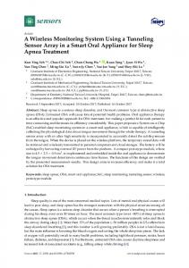
System Architecture Currently, we are developing wireless sensor network for monitoring CO and CO2 system as shown in Fig. 1. Gas sensor
node is a device composed of CO sensor (TGS2442), CO2 sensor (TGS4161), Waspmote Gases 2.0 board, and Waspmote PRO 1.2. A sensor node has to be connected to the battery as a power source and XBee module (IEEE 802.15.4 Zigbee protocol) as a means of wireless communication. Gas sensor nodes are placed in some areas that you want to sense and to gather data of CO and CO2 concentration in the environment. There is a computer server that is connected to a gateway directly using Ethernet protocol. The gateway uses Meshlium from Libelium. Data from the sensor nodes are sent to a gateway using the IEEE 802.15.4 Zigbee protocol. Computer server is in charge of storing the data into the database and processing it by monitoring application.
Fig. 1 System Architecture Gas sensor node has a MAC address on the XBee module that distinguishes between one another. XBee module is in charge of sending the data wirelessly using IEEE 802.15.4 Zigbee protocol to the gateway that has been determined. Meshlium gateway serves as a receiver data obtained from the environment (via sensor nodes) to be processed by the computer server. Retrieval of data by sensor nodes performed every 60 seconds and immediately sent to the computer server through Meshlium gateway. Furthermore, the data received by the server computer will be saved to the database and can be processed. To be able to communicate and transmit data wirelessly, a sensor node or end-device requires a Zigbee module. In addition, to be able to use the entire module is used (including Gas sensor), such devices require additional power from the battery. 2.2
Component of System The specifications of the hardware used in this paper are shown on Table 1: Table 1 The specifications of the hardware a. CPU: 3.20 GHz (Intel Core i5) 1. Computer as server b. Memory: 4.0 GB RAM a. Waspmote PRO 1.2 b. Waspmote Gases 2.0 board 2. Sensor node and c. CO sensor (TGS2442) Gateway d. CO2 sensor (TGS4161) e. Xbee S1 module f. Meshlium Gateway
Copyright © TAETI
International Journal of Engineering and Technology Innovation, vol. 6, no. 1, 2016, pp. 79 - 91
82
The installation contains sensor node, Meshlium gateway and switch for connecting to the local network. A server computer is connected to the switch directly using Ethernet. It’s also done on Meshlium to make them have the same network.
2.3.
Sensor Modules We use TGS2442 sensor for sensing CO and TGS4161 sensor for sensing CO2. These sensors will be planted on
Waspmote Gases 2.0 board connected to the microcontroller Waspmote PRO 1.2. The TGS2442 is a resistive sensor sensitive to the changes in concentration of carbon monoxide (CO) and, very slightly, hydrogen (H2). It measures a value between 30 and 1000ppm. This sensor will be placed in socket 4 of Waspmote Gases 2.0 board. Reading this sensor requires a cycle of one second throughout which two power supply pulses are generated on heat resistance and sensor resistance of 14ms and 5ms each (average consumption throughout the power supply cycle is 3mA). The execution of this cycle and the reading of the sensor can be done automatically using the functions of the SensorGasv20 library. The TGS4161 sensor provides a voltage output proportional to the CO2 concentration in the atmosphere. This sensor must be placed in socket 1A of Waspmote Gases 2.0 board. It shows a value between 220 and 490mV for a concentration of 350ppm (approximately the normal CO2 concentration in the air) decreasing as the amount of gas increases. Different sensors may show a large variability in the initial voltage values at 350ppm and sensitivity, so it is recommended to calibrate each sensor before including it in the application. 2.4. Configuring Waspmote Sensor Node To perform the role of end-device, sensor nodes must be programmed beforehand. First of all, we set up the source code to activate the function of CO and CO2 sensors. Source code can be opened using Waspmote IDE based C programming language. Fig. 2 shows source code to get data from the environment.
Fig. 2 Get Data from Environment Code Sensors will take gas concentration values of the environment in the form of electric voltage (volts) using readValue() function. Then, the value will be converted to part per million (ppm). For CO gas, the voltage value is converted to resistance
Copyright © TAETI
International Journal of Engineering and Technology Innovation, vol. 6, no. 1, 2016, pp. 79 - 91
83
using calculateResistance() function. After having obtained the resistance value, we convert that value into ppm using calculateConcentration() function. The value of CO2 sensor voltage can be converted into ppm directly using the formula pow(10, (co2Val + 158,631) / 62,877) [11], where co2Val is variable storing the voltage of CO2 sensor. To be able to transmit data to Meshlium gateway, a Waspmote which acts as an end-device has to be programmed sending a frame to the Meshlium’s MAC address. The following source code for delivering data that has been collected by sensor nodes to the gateway Meshlium as seen in Fig. 3. We have to determine the type of frame that we use. There are two types of frame that can be used, ASCII and BINARY. ASCII frame structure is designed to make users read the frames sent conveniently. With ASCII frame, the payload written with ASCII characters is certainly more readable, while the BINARY frame structure made to compress the frame. The main goal of defining binary fields is to save bytes in frame’s payload in order to send as much information as possible. Certainly with BINARY frame, it’s not easy to read the data in the frame. We can also enter the ID Waspmote to give identifier for devices that we use. Frames can be made using frame.createFrame() function followed by the type of frame that we choose and Waspmote ID that we want. And then, we have to determine the data we send. We specify the sensor used and the variable stored the sensor data by using frame.addSensor() function. Furthermore, we need to set the packet carrying the frame. To be able to temporary stored the data carried by the frame, a packet memory should be allocated in advance by using packet = (packetXBee*) calloc(1, size of(packetXBee)). We also have to set the mode of packet transmission. There are two types of packet transmission mode, unicast and broadcast. We use unicast mode because the sensor node will send packet only to the Meshlium gateway directly. Unicast mode is used to send packets from a single node to one another node. The broadcast is used to send packets from a single node to the entire node in the same network. Lastly, we must determine where the packet containing the frame sent. We can use xbee802.setDestinationParams() function to determine the packet destination by entering packet’s variable and destination MAC address. And then, the packet will be sent to the destination by using xbee802.sendXBee(packet).
Fig. 3 Xbee Communication Code 2.5. Configuring Mehlium Gateway Meshlium gateway is a Linux router that can contain five different radio interface: WiFi 2.4GHz, WiFi 5GHz, 3G/GPRS, Bluetooth, and ZigBee. Meshlium can also integrate GPS modules for mobile and vehicle applications, and it can have energy sources such as solar and battery system. These features are fitted with a protective aluminum IP65 allowing Meshlium to be
Copyright © TAETI
International Journal of Engineering and Technology Innovation, vol. 6, no. 1, 2016, pp. 79 - 91
84
placed outside the room. Meshlium is a complete Linux tool that offers a wide range of services, programming environment and storage systems. Meshlium has enabled HTTP / HTTPS and SSH in it. Meshlium also supports a wide variety of programming environments including C, C ++, Java, PHP, Python, Perl, and Ruby. Related information storage, Meshlium equipped with two different database systems, MySQL and Postgre. Meshlium has a local database that can hold the data that is sent to it until 29,5 GB, depending on the storage size. All information coming from all interfaces (ZigBee, Bluetooth, 3G/GPRS, WiFi and GPS module) can be stored in the Local File System Database or even exported to external database to the internet. In this system, after the sensor node is able to get data from the environment and ready to send it, Meshlium also has to be set in advance to be able to receive the data from sensor node. Meshlium has user interface for system configuration called Manager System, which is similar to configuration application on router or gateway in general. By default, Manager System can be accessed using a web browser via Ethernet using 192.168.1.100 and via WiFi using 10.10.10.1. The initial view of Manager System will appear after we enter the username and password correctly. The main settings that must be done are PAN ID (Network ID) and Channel as shown in Fig. 4. PAN ID (Personal Area Network) is a network ID with a hexadecimal value between 0 and 0xFFFF. So there are 65536 possibilities that can be used. XBee can only communicate with one another if they have the same network ID. CH (Channel) sets the frequency band used by XBee to communicate with each other. XBee generally operates on the 2.4 GHz band. To be able to connect our system with local network, we have to setting the Meshlium Ethernet configuration. This configuration can be done in the Interfaces tab in the Manager System as shown in the Fig. 5. The network topology as shown in Fig. 6. There is a switch connected directly to the Meshlium gateway using an Ethernet cable. The switch has an IP 10.252.13.1, and we will set the Meshlium IP to 10.252.13.225. There is a computer, acting as a server, which is connected directly to the switch using an Ethernet cable. The computer’s IP address will set to 10.252.13.200. The server computer in charge of storing the external database synchronized with Meshlium local database.
Fig. 4 Meshlium Zigbee Configuration
Fig. 5 Meshlium Ethernet Configuration
3. Experiment Result In the experiment phase, we use three sensor nodes connected to the Meshlium gateway. Gateway is connected to a computer server via a local network using a switch. Network topology in the experiment is shown in Fig. 6.
Copyright © TAETI
International Journal of Engineering and Technology Innovation, vol. 6, no. 1, 2016, pp. 79 - 91
85
Fig. 6 Network Topology Each sensor node has a MAC address that is different and represented by id_secret in the database. Meshlium gateway is a device with a Linux operating system. To know the contents of its Linux directory, we can access the Meshlium using an SSH connection. One of the most important components in Meshlium is sensor parser. This file is used to convert the frames sent by the sensor node and processed by the gateway. After the frame can be read, each value carried by the frame will be in inserted into Meshlium local database. Meshlium has MySQL local database to accommodate the values of the converted frame. Meshlium local database would be very vulnerable to damage and memory limitations of storage, so it is advisable to back-up the data to an external database. Meshlium has data synchronization system to external database directly at certain intervals. To synchronize, we need to set the IP address where the database created, the name of the database that will be used, username and password. In addition, the table structure used should adjust the structure of the tables in the local database. This is because the system synchronization follows the structure of the table on the local database Meshlium, while the structure of the table on the local database follows the insertion pattern of the sensor parser. Furthermore, at the Sensor Network tab, there is Capturer tab in the side bar. In Capturer tab, we can see the contents of the frame sent by the sensor node. As we mentioned earlier, the sensor node transmits data in the form of a frame which is converted by Meshlium sensor parser. When we set the Local database to store all data received, we can see all data in the local database that have been received as shown in the Fig. 7. Frame conversion result would be inserted into the table by following the structures below: Id is the numbering of the records. Id is an integer auto-increment value with 11 digits maximum length. Id_wasp is a string defined by the user which may identify each sensor node (Waspmote) inside the user’s network. When the user do not want to give any identifier, the field remains empty indicated. Id_secret is an id that distinguish device between one another. Id_secret represents the MAC address of each sensor node. Frame_type is used to determine the frame type. There are two types of frame: Binary and ASCII. Frame_number is a numbering for each delivery made by each device. Sensor indicated type of sensor we use. Copyright © TAETI
86
International Journal of Engineering and Technology Innovation, vol. 6, no. 1, 2016, pp. 79 - 91 Value is the value read by the sensor node associated sensor used. Timestamp shows the time when a frame is received by the gateway. Raw is used to store a frame that failed to be converted by the sensor parser.
Fig. 7 Meshlium Local Database Fig. 8 shows the synchronization of the local database to an external database. For synchronization, we use the IP address of computer server that has been connected to our system. We can also synchronize data automatically by specifying a particular interval. Synchronization can be performed automatically during Meshlium and server computers alive. Synchronization result can be viewed by pressing the Show Data.
Fig. 8 External Database Synchronization We can also see the results of the synchronization to the external database on the computer server. Fig. 9 shows the results of external database synchronization.
Copyright © TAETI
International Journal of Engineering and Technology Innovation, vol. 6, no. 1, 2016, pp. 79 - 91
87
Fig. 9 External Database Our system has a desktop application to display the data synchronized. The application runs on the computer server and can only be accessed by authorized user. We can monitor the changes of value in real-time with a 5 minute interval. This interval is actually according to the interval data transmission by using desktop application. To display the data in real-time, we can open the Real-time tab as seen in Fig. 10. First, we have to choose the device that will be displayed, click Device drop down to do so. There will be three devices that can be selected. Then, to start reading its value, we can press the Sense button. Sense is a toggle button; this button will turn into Stop button (after you click Sense). It is used to stop the reading of the received value. The result can be seen in Fig. 10 below.
Fig. 10 Desktop Application Real-time Feature We also can see data from a certain date through the Record tab. In Record tab, there are two sidebars: Graph and Table sidebar as shown in Fig. 11. Once we select the device and the date, click the Show button to display the data according to the device and the date we set. Then the data will be taken from external database and then displayed in graphs and tables. The field shown in Table sidebar is all fields in the database, so basically we display the information of frame stored. We design this feature for users who use desktop application, so they can perform further data analysis.
Fig. 11 Desktop Application Record Table
Copyright © TAETI
88
International Journal of Engineering and Technology Innovation, vol. 6, no. 1, 2016, pp. 79 - 91 We show the data on the table while displaying the graphics so that the user can easily observing. Graphic display, as
shown in Fig. 12, can be viewed by moving to Graph sidebar.
Fig. 12 Desktop Application Record Graph For public accesses, our system provides a website for displaying the stored data. When user accesses the website, its Dashboard will be shown. We can see the results of the data readout from the environment in graph and table. As seen in Fig. 13, when we choose Summary Chart tab on the sidebar, the page to display the data in graphs will appear. On this page, we can display a summary of CO and CO2 values within a certain time frame. First of all, we need to select the device which we want to see. We can see a summary value of CO and CO2 concentration for today, this month, or this year, by clicking the button according to the desired time frame.
Fig. 13 Website Summary Chart To view a summary of the value in table, we can open the Summary Table in the sidebar tab. The step that must be done is almost the same as displaying data in the graphic. We need to select the device which we want to see. We can see a summary value of CO and CO2 concentration for today, this month, or this year, by clicking the button according to the desired time frame as shown in Fig. 14.
Copyright © TAETI
International Journal of Engineering and Technology Innovation, vol. 6, no. 1, 2016, pp. 79 - 91
89
Fig. 14 Website Summary Table In addition, we also can see a graph of data recorded according to a certain date through the Record tab. When we choose the tab, the page to see the recorded values in a certain day will appear. Just like before, we need to choose the device that we want to see. We can also choose All Devices to see the value of the entire devices being used. Then we also need to choose a specific date. The result is shown in Fig. 15 (one device selected) and Fig. 16 (all devices selected).
Fig. 15 Website Record One Device Selected
Fig. 16 Website Record All Devices Selected
Copyright © TAETI
International Journal of Engineering and Technology Innovation, vol. 6, no. 1, 2016, pp. 79 - 91
90
Based on the above results from IPOM design and related works, we have considered six parameters to show the contribution of IPOM design to implement gas monitoring wireless sensor network such as sensor type, wireless transmission module, environment (indoor or outdoor), microcontroller, gateway, and backup service (i.e., database backup and synchronization) as shown on Table 2. Table 2 Comparison between design of IPOM and related works Model
Sensor
Yang [4] Sivaraman [5]
CO2 CO2, NO2, O3 Temperatur, Humidity
Peng [6] Kadri [7] Jelicic [8] Dian [9] Proposed Model
O3, CO, NO2, H2S
Wireless Transmission GPRS GPRS
ARM Cortex-M3 NA Arduino Atmel 8-bit AVR
Hardware (Gateway) No Gateway No Gateway Arduino Atmel 8-bit AVR
Backup Service No No
Environment
Microcontroller
Outdoor Outdoor
ZigBee
Indoor
No
GPRS/3G
Outdoor
ATmega2560
No Gateway
No
Metal Oxide Semiconductor (MOS), Pyroelectric InfraRed (PIR) CO2
ZigBee
Indoor
Jennic JN5148
No Gateway
No
WLAN
Indoor
NA
No Gateway
No
CO, CO2
ZigBee
Outdoor
ATmega1281
Meshlium
Yes
4. Conclusions This paper explains development of an integrated pollution monitoring (IPOM) system to monitor the concentration of air pollution using gas sensor and Meshlium gateway. We analyze the data received from sensor nodes to server receiver can be converted by Meshlium using its sensor parser. We can join our local area network and our wireless sensor network. By joining our network, we can use a server computer to manage the data sent by sensor nodes. Meshlium also has synchronization system to synchronize its local database and our external database in server computer. The experiment results show that the sensed data from environment can be displayed through wireless sensor network in desktop application and website to monitor the environment condition from distant. For the future work, we will add more meshlium gateway and sensor node to increase the coverage area, and use WiFi/3G/GPRS to increase scale of pollution monitoring system.
Acknowledgement This research was supported by Ministry of Research, Technology and Higher Education of Indonesia, INSINAS Scheme.
References [1] Y. Xiang, R. Piedrahita, R. P. Dick, M. Hannigan, Qin Lv, and L. Shang, "A hybrid sensor system for indoor air quality monitoring," Proc. IEEE International Conference on Distributed Computing in Sensor Systems (DCOSS), IEEE Press, May 2013, pp. 96-104. [2] B. H. Lee, M. U. H. Al Rasyid, and H. K. Wu, "Analysis of superframe adjustment and beacon transmission for IEEE 802.15.4 cluster tree networks, " EURASIP Journal on Wireless Communications and Networking, vol. 2012, July 2012. [3] M. U. H. Al Rasyid, B. H. Lee, A. Sudarsono, and Taufiqurrahman, "Implementation of body temperature and pulseoximeter sensors for wireless body area network," Sensors and Materials, vol. 27, pp. 727–732, September 2015. [4] H. Yang, Y. Qin, G. Feng, and H. Ci, "Online monitoring of geological CO2 storage and leakage based on wireless sensor networks," IEEE Sensors Journal, vol. 13, pp. 556-562, October 2012. [5] V. Sivaraman, J. Carrapetta, K. Hu, and B. G. Luxan, "HazeWatch: A participatory sensor system for monitoring air pollution in Sydney," Proc. IEEE 38th Conference on Local Computer Networks Workshops (LCN Workshops), IEEE Press, Oct. 2013, pp. 56-64.
Copyright © TAETI
International Journal of Engineering and Technology Innovation, vol. 6, no. 1, 2016, pp. 79 - 91
91
[6] I. H. Peng, Y. Y. Chu, C. Y. Kong, and Y. S. Su, "Implementation of indoor VOC air pollution monitoring system with sensor network," Proc. Seventh International Conference on Complex, Intelligent, and Software Intensive Systems (CISIS), IEEE Press, July 2013, pp. 639-643. [7] A. Kadri, E. Yaacoub, M. Mushtaha, and A. A. Dayya, "Wireless sensor network for real-time air pollution monitoring," Proc. International Conference on Communications, Signal Processing, and their Applications (ICCSPA), Feb. 2013. [8] V. Jelicic, M. Magno, G. Paci, D. Brunelli, and L. Benini, "Design, characterization and management of a wireless sensor network for smart gas monitoring," Proc. 4th IEEE International Workshop on Advances in Sensors and Interfaces (IWASI), IEEE Press, June 2011, pp. 115-120. [9] F. Dian, "Development of novel gas detection wireless sensor node," Proc. Spring Congress on Engineering and Technology (S-CET), May 2012, pp. 1-3. [10] G. Pau, "Power consumption reduction for wireless sensor networks using a fuzzy approach," International Journal of Engineering and Technology Innovation (IJETI), vol. 6, no. 1, pp. 55-67, January 2016. [11] "GitHub Repository Arduino Code," https://github.com/fablabbcn/ASK-Shield/blob/master/ArduinoCode%20-%20ASK%20Shield/SensorTest/SensorsTest_A SK/co2.ino, September 11, 2015.
Copyright © TAETI