Draft of 26 April 1995
POSD - a notation for presenting complex systems of processes Peter Henderson1 and Graham D Pratten2 Keywords: legacy systems, distributed systems, adaptability, process modelling, dataflow diagrams, lifecycle costs
Abstract When trying to understand the behaviour of large systems, such as the business processes of large enterprises, we often adopt diagramming techniques based on derivatives of data flow diagrams. For very complex systems such diagramming techniques suffer from the inability to abstract uniformly from arbitrary subcollections of components. In this paper we present an extension to conventional diagramming techniques which solves this problem. We describe how we have applied this technique to some very complex business systems and illustrate its main points with a simple example. While we have used the notation to present process models we conclude that it is applicable to the description of behaviour in any complex system of processes.
Background We are concerned with the nature of change in large and complex computer-based systems. In particular we are concerned with distributed systems, comprising many individually complex, legacy components. Such systems have become the basis of all large commercial or industrial enterprises. But the nature of the business in which these enterprises engage is constantly changing. So it is necessary to change the supporting computer systems if these enterprises are to remain competitive. We conjecture that the right way to go about such changes, given the constraints imposed by the legacy systems, is to model the business process which the enterprise system supports and to show how this process maps onto the legacy components [1].The model must be in a form which the owners of the business process can understand, so that the proposed changes can be properly discussed with them and so that the impact of alternative changes can be assessed by them. We take this need for business user involvement to imply that the model must be presented in diagrammatic form. We have used many types of diagramming technique in our work. Data flow diagrams of the SSADM, SADT, IDEF or Petri Net variety are probably the simplest for business users to comprehend intuitively [2].Consequently they are the kind of diagram we have made most use of over the years. But they each suffer from a drawback which we have come to call the “wire syndrome”. Usually such diagramming notations use two types of component, boxes (typically) to denote processing and lines to denote data flow. The notation usually allows boxes to be nested, but no matter how deeply the hierarchy is formed, usually the items flowing between processes are at the same level of abstraction from the most detailed to the highest level diagram. For large, complex systems this proves to be a drawback. Hardware engineers have noticed a similar phenomenon (hence our use of the term “wire syndrome”) in that all their diagrams whether of a low or high level of abstraction, the lines always correspond to physical wires, or at best bundles of wires, in the eventual implementation. Over the last two years we, along with colleagues, have developed models of a number of very large businesses. For example we have modeled a significant part of the business process of the Inland 1
Department of Electronics and Computer Science, University of Southampton, SO17 1BJ (UK)
[email protected] http://louis.ecs.soton.ac.uk/~ph/cv.html
2
International Computers Ltd, Kidsgrove, Stoke on Trent, ST7 1TL (UK)
[email protected]
Draft of 26 April 1995
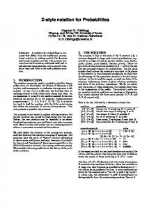
Revenue. The most detailed models were indeed data flow models. But abstractions from them were presented in a new form which we have called POSD diagrams (for Process Oriented System Design). Figure 1 shows a POSD diagram of a part of another business system we have modeled for the retail sector. This will be described in the next section when POSD notation is discussed. Each of these business systems is modeled at many levels of abstraction and thus it is possible to show the mapping between levels. Also, different views of the same system are possible. In particular there is the low level view where the basic components map exactly on to services provided by the distributed support system. One can abstract from that in different ways, combining components into higher level collections based on the structure of the distributed system or based on the structure of the component business processes. These two views in particular allow one to judge the effect of proposed business process changes in terms of the changes required to the legacy systems.
POSD Notation The name we have given the notation reflects our current use for it. We are using POSD (Process Oriented System Design) notation to model the business systems of large end-user organizations. We will normally model the existing business processes and, because proposed changes are the driver, we will then model alternative future reorganizations of the business process. By showing the mapping to the installed legacy computer systems we can discuss the cost/benefit of each proposal with the owners of the business process. POSD is always used in conjunction with some base-level modeling language, such as data flow diagrams. Typically, early attempts at modeling a business process, are at (or only a little above) the data flow (document flow, work flow) level. After a while our understanding of the model is such that we can begin to form more abstract views. The principal way in which this happens is by a process of abstraction from the low-level data flow diagram. Logically related components are combined into more abstract entities, and eventually a hierarchical view is arrived at bottom-up. It is this process of abstraction which the data flow diagram (and its relations) does not support sufficiently well. What we needed was a notation which allowed arbitrary subcollections of components to be
Promoter
Consumer Inducement
Retail Outlet Purchase
Redemption
Figure 1 POSD model of Retail Promotion Scheme
combined to form a single new, more abstract component. The consequence of this observation is that whatever the nature of a collection of components there must be an abstract component of a suitable “type” to which we can abstract that collection. The simplest solution to this apparent dilemma is to have only a single type of component. Since we a primarily concerned with process modeling we have termed our single component type a “behaviour”. A behaviour is a system which has state, performs internal actions and interacts with other behaviours. Elsewhere we have given a more comprehensive description of this concept [3]. Clearly we can see that the usual process/activity element of a data flow diagram is a behaviour. So too are the usual data repository components. So too, with a little more thought, are the various means of data transfer among components.
POSD - a notation for presenting complex systems of processes P Henderson and G. D Pratten
2
Draft of 26 April 1995
Consider the simple POSD model shown in Figure 1. This comes from our model of a business process in Retail where the Consumer will Purchase from a Retail Outlet. The fact that the Consumer’s interface with the Retail Outlet is a Purchase is denoted by the juxtaposition of the boxes. Each is a behaviour. At this level of detail we have not said whether the method of purchasing is direct or by mail order or any of a wide variety of schemes. There are other relationships shown in the diagram. A Promoter encourages the Consumer to make certain purchases by offering Inducements (typically the promise of a gift or a discount). The Consumer can subsequently redeem this inducement, apparently by an interaction (called Redemption) with the Promoter. This particular abstract model is only one of many views of the Retail business process derived from lower-level data flow diagrams. Some views are organised (as this one) to show the business oriented abstractions while others are organised to show the location of the distributed systems.which support this process. Each box in a POSD diagram is a behaviour. The behaviour of an outer box is implemented by the combined behaviours of the inner boxes. If two boxes touch this implies that there is direct interaction between them. If two boxes do not touch this implies there is no direct interaction between them. We have not restricted interaction to data (or other artifact) flow. Since behaviours will be made up of component behaviours we will expect interaction between touching behaviours to be realized in some way at the more detailed level. We refer to the fact that two behaviours touch as a promise that we will
A
B C
A
D
B
A
B C
C
Figure 2 Ways in which Promises are fulfilled
(in a more detailed diagram) define how that interaction is accomplished. There are basically three ways in which it can be accomplished as shown in Figure 2. A and B are behaviours which interact. This interaction is accomplished either by the fact that each contains a sub-behaviour which interact in turn (C interacts with D) or one contains a sub-behaviour which interacts with a parent (C interacts with B) or finally there is a shared sub-behaviour C which is common to both. These are all the core concepts of POSD. POSD is intended for use with a suitable base-level modeling notation. We have used it with DFD’s, with Role Interaction Diagrams, with Finite State Machine notations and with Petri Nets. As an illustration of how this interworking is accomplished we turn in the next section to a very simple example.
A Simple Example Worker
Worker
Figure 3 Two workers interacting in a business process
Consider the simple process model shown in Figure 3. This shows two workers whose activity in a business requires them to interact. In more detail, as Figure 4 shows, each worker is implemented by a Person and these Persons actually interact through a Mail System. The Mail System is shown as a shared behaviour of the two Workers.
POSD - a notation for presenting complex systems of processes P Henderson and G. D Pratten
3
Draft of 26 April 1995
Worker
Worker Person
Person Mail System
Figure 4 Simple Communication Subsystem
Although this example is very simple, the structure it represents, of two behaviours interacting through an intermediary, is commonplace in the systems we have to describe. The earlier example contains a number of instances of this structure. We have chosen to detail the interaction between a Person and the Mail System as shown in Figure 5. Here we show that the Person and the Mail System each contain sub-behaviours which we have called Send and Receive. The interaction between a Person and a Mail System is fulfilled by the interaction between a Send and a Receive.
Person
Mail System Send
Receive
Receive
Send
Transfer
Send
Receive
Figure 5 Detail of Communication
At the next level of detail we have to show how the Send and Receive behaviours interact. We have supposed that this model is bottomed-out as a Petri-Net. Some of the detail is shown in Figure 6. Here we have a shared behaviour common to both Send and Receive.
POSD - a notation for presenting complex systems of processes P Henderson and G. D Pratten
4
Draft of 26 April 1995
Send
Receive
Figure 6 Shared Behaviour
Of course the purpose of these models is for us to be able to confirm that we have made an accurate presentation of the system and for us to be able to discuss the system with the owners of the business process. It is most likely that we would show only the top-level most abstract models to the business process owner, reserving the more detailed (and demanding) models to our own technical uses. Nonetheless, the lower level models are vital to an accurate presentation of the abstract models and, as we said earlier, are often the way-in to the modeling project. This is because it is often easier to get to grips with detail to begin with. When abstraction comes, it is of course the key to a clear presentation, which is in turn the key to clear understanding. And understanding must precede cost effective change.
Conclusions The method we have presented has served us well in a number of large scale system analysis activities performed by ICL. In particular, models of the business processes of the Inland Revenue, of a Retail business and most recently of a News Agency business have been built on behalf of customers. The analysis has involved traditional tools and techniques complemented by POSD. In particular we have used the Process Wise process modeling tools which are a commercial product based on the IPSE 2.5 research prototype ([4], [7], see also [6]) to capture many of the base level processes. Process Wise has been extended to include POSD diagramming capability. We plan further tools, in particular a database/configuration management tool which will allow the organization and reorganization of a large set of inter-related diagrams. During the POSD analysis process, as with any systems analysis process, many diagrams are generated which are eventually superseded by improved diagrams. But in POSD, we also need to maintain simultaneously many different views (abstractions) of the same base process. The importance of documentation in the engineering of large complex systems is well established [5]. Consequently, a tool to facilitate the production of different presentations is urgently needed. POSD is in the later stages of definition. It has been case hardened. The concepts presented here are just the core concepts. In practice it is necessary to adopt naming conventions for components which mirror the customer’s usual conventions. We have methods of naming types and instances of behaviours which satisfy this need. Also in practice it can be useful to use diagramming conventions different from those used here. For a long time we used both boxes and lines (which we tried to think of as shriveled boxes).to overcome some predictable topological problems (e.g. 5 boxes all of which need to touch each other). Lately we have dropped this extension ourselves because we believe it encourages us to accept still-too-complex models. But we are not certain that we won’t return to it and we don’t discourage it in others. POSD has been presented as a process modeling method, specifically for business processes. But we believe that it can be used more widely. Indeed for anything that data flow diagrams or finite state models or indeed Petri Nets have been used for, both hardware and software. We are planning such
POSD - a notation for presenting complex systems of processes P Henderson and G. D Pratten
5
Draft of 26 April 1995
applications ourselves and hope soon also to have a formal reference model with which we can confirm some of our conjectures about the applicability of the ideas.
References [1] Peter Henderson Software Processes are Business Processes Too 3rd International Conference on the Software Process, IEEE Computer Society Press, Oct 1994 [2] John Buxton and John McDermid Architectural Design in Software Engineer’s Reference Book, Butterworth Heinemann, 1991 [3] Peter Henderson and Graham D Pratten POSD - Process Oriented System Design, CS/IN/2296, International Computers Ltd, February 1995, accessible from http://louis.ecs.soton.ac.uk/~ph/cv.html [4] Robert A Snowdon An introduction to the IPSE 2.5 Project ICL Technical Journal 6(3), 1989 [5] David L Parnas Software Aging Proceedings of the 16th International Conference on Software Engineering, IEEE Computer Society Press, 1992 [6] Ian Robertson An Implementation of the ISPW-6 Process Example in Software Process Technology, Proceedings of EWSPT 94, Springer Verlag, LNCS 772, 1994 [7] Brian C Warboys The IPSE 2.5 Project: Process Modelling as the basis for a support environment in Proceedings of the First International Conference on Software Development Environments and Factories, Berlin 1989
POSD - a notation for presenting complex systems of processes P Henderson and G. D Pratten
6