position. This algorithm uses mainly the information from the. IMU and minimizes ... Electronics Engineering of Mindanao University of Science And Technology.
Int'l Journal of Computing, Communications & Instrumentation Engg. (IJCCIE) Vol. 3, Issue 2 (2016) ISSN 2349-1469 EISSN 2349-1477
Position Estimation using Inertial Measurement Unit (IMU) on a Quadcopter in an Enclosed Environment Christian B. Abellanosa, Ruth Pearl J. Lugpatan, and Diogenes Armando D. Pascua
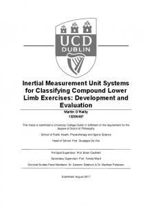
(DIY) quadcopter. The parts included to make this quadcopter are four motors that were connected to an Electronic Speed Controller (ESC), a li-po battery, a microcontroller or a microprocessor, and various sensors. The flight controller chosen by the researchers is an ATMega328 microcontroller with an MPU6050 sensor as shown in Figure 2. This microcontroller is where the code was uploaded to do all the processes for maneuvering the quadcopter and the position estimation
Abstract— Inertial sensors, like accelerometers and gyroscopes, are rarely used by themselves to measure displacement. Currently, the use of low cost IMUs for this particular application is very impractical due to the accumulation of errors from various sources. In this study, a position estimation using Inertial Measurement Unit (IMU) in a quadcopter is developed. The objective of the researchers is to develop an algorithm that will make the quadcopter travel a certain displacement or position. The algorithm uses mainly the information from the IMU and minimizes the error between the desired displacement and the actual displacement travelled by the quadcopter. The implemented approach is to use an error factor. The error factor is a value that is inversely proportional to the desired displacement. Experiments indicate that the system provides accurate pose estimates and are robust. Keywords-Accelerometer, Gyroscopes, Inertial Measurement Unit , Quadcopter
I. INTRODUCTION As Inertial Measurement Unit(IMU) sensors are unable to measure position directly (only angular velocity and acceleration), precisely determining the position of quadcopters using IMU has been proven to be a great challenge, especially in applications where the displacement is to be estimated over a long period of time due to error accumulation in the acceleration measurement. This study describes a method to implement a double integration of the signal obtained from the sensor using a microcontroller to obtain position. The objective of the study is to develop an algorithm that will make the quadcopter travel a certain displacement or position. This algorithm uses mainly the information from the IMU and minimizes the error between the desired displacement and the actual displacement travelled by the quadcopter.
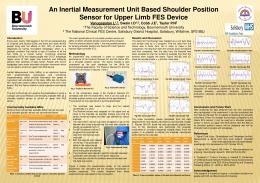
Fig. 1. The Quadcopter Hardware Components.
II. METHODOLOGY A. Hardware Design of the Quadcopter The hardware design ,as shown in Figure 1, have a major role in the algorithm for flight of the quadcopter. The quadcopter developed by the researchers is a Do-It-Yourself
Fig 2. MPU6050 Inertial Measurement Unit Sensor
B. Software Design of the Quadcopter The general algorithm for the development of the software to be uploaded to the to flight controller of the system is outlined in Figure 3.The use of Proportional Integral Derivative (PID) control as well as Kalman filtering are essential components of the system software.
Christian B. Abellanosa, and Ruth Pearl J. Lugpatan are graduates of BS Electronics Engineering of Mindanao University of Science And Technology. Diogenes Armando D. Pascua is now with the Department of Electronics Engineering of Mindnanao University of Science And Technology, CM Recto Avenue, Lapasan, Cagayan de Oro, 9000 Philippines.
http://dx.doi.org/10.15242/IJCCIE.AE0516306
332
Int'l Journal of Computing, Communications & Instrumentation Engg. (IJCCIE) Vol. 3, Issue 2 (2016) ISSN 2349-1469 EISSN 2349-1477
Fig. 3 General Flow Chart of the Software
B. Position Estimation Method As illustrated on Figure 3, the orientation and linear acceleration of the quadcopter must be known before double integration takes place. In order to determine the orientation of the quadcopter, acceleration values are needed. The acceleration data are noisy, resulting to a noisy orientation reading. Therefore, the researchers used a Kalman Filter to further filter out acceleration noise. After filtering the acceleration values, the researchers then calculates the orientation of the quadcopter for roll angle (ϕ) and pitch angle (θ). For the quadcopter to travel a distance, it needs to tilt its body with respect to its roll and pitch angle. As it tilts an angle, the accelerometer is getting acceleration values with gravity. Before the researchers can calculate the displacement obtained by the quadcopter, linear acceleration must be known first, thus it is essential to remove gravity in acceleration of x and y axes. In calculating the linear acceleration, equations 1 and 2 are used by the researchers. Ax-linear = (Ax – 9.81sin ϕ)/ cos ϕ (1) Ay-linear = (Ay – 9.81sinθ)/ cosθ (2)
Noise and drift in sensors’ data are not good values to work with. The researchers used the configurable Digital Low Pass Filter of MPU6050 on board for both gyroscope and accelerometer. Filtered accelerometer and gyroscope raw readings which are in binary units were converted to its appropriate units for acceleration and angular velocity. The acceleration should be in units of m/s2 and the angular velocity should be in degrees/s. The researchers will use 1670.133/(m⁄s^2 ) accelerometer factor and 131.072/(°⁄s) angular velocity factor. A. Algorithm for Flight Quadcopters are aerodynamically unstable, which is why they can’t be controlled just by changing the speed of the motors linearly with respect to the radio controller inputs (Aileron, Elevator, Rudder and Throttle). This is why an IMU has to be used to remove the error between quadcopter’s real orientation and reference orientation from the radio controller. This is the update process of the PID controller. The controller outputs a control signal used to control the speed of the actuators. On this section, the PID output is calculated and will affect the speed of the motors. PID controller has three gains, an input, a setpoint and bounds. These three gains affect how aggressive the PID controller operates. PID input is the value coming from the sensors. PID setpoint is the value calculated from the receiver data. PID bounds is the limit of the PID output. The relationship between the three-axis sensor and throttle inputs with four outputs in the motor control system as a whole was shown in figure 4. Figure 5 shows the corresponding codes in the Arduino environment of the PID Controller Block Diagram.
http://dx.doi.org/10.15242/IJCCIE.AE0516306
333
Int'l Journal of Computing, Communications & Instrumentation Engg. (IJCCIE) Vol. 3, Issue 2 (2016) ISSN 2349-1469 EISSN 2349-1477
Start Linear Acceleration of x and y axes First Integration Velocity of x and y axes
Desired Displacement
Second Integration
Error Factor Calculation Fig. 4. PID Controller Block Diagram
Displacement of x and y axes
1/Error Factor
Pythagorean Theorem
Fig 5. Code snippet for determining which motor is affected by a particular PID output
Resultant Displacement
Figure 7 shows the position estimation method implemented by the researchers. Double integrating the linear acceleration will result to displacement in the x and y axes. The corresponding codes for double integration and pythagorean theorem for calculating the resultant displacement can be observed in Figure 6.
Equal?
STOP
Fig. 7. Position Estimation Method
After the researchers had plotted the error factor curve, an equation of the curve was generated with respect to the percentage error. This equation was used to correct the desired displacement of the quadcopter and the actual displacement. Error factor is the value calculated using a desired displacement to achieve a particular percentage error. This value determines when the quadcopter will stop moving. Error factor is different for different desired displacements. The quadcopter will stop moving whenever the calculated resultant displacement travelled by the quadcopter is equal or greater than 1 divided by the error factor. The calculated resultant displacement is incomparable to the actual displacement travelled by the quadcopter because of the errors present from the sensor itself to the noise effects. For instance, the desired displacement is 5 meters, the calculated resultant displacement may not be equal to 5 meters and it may be more or less. The error factor determines what value of resultant displacement is calculated before the quadcopter stops and will yield approximately 5 meters away from the initial point.
Fig. 6. Code snippet for double integration and calculating the resultant displacement
In order to minimize the error between the desired displacement and the actual displacement made by the quadcopter, the researchers obtained an error factor. The quadcopter will stop travelling when its resultant displacement reaches a value equivalent to 1/error factor. The process of how the researchers obtained an error factor equation can be observed in Figure 8. The error factor which is a function of desired displacement is not linear, thus, the researchers must conduct a test to achieve the error factor curve with a unit measure of 1 meter. The researchers conducted a test where error factors are pre-set starting from 6 to 192 to determine what percentage errors these error factors yield. Using these percentage errors, the researchers are then able to derive it to a desired displacement.
http://dx.doi.org/10.15242/IJCCIE.AE0516306
334
Int'l Journal of Computing, Communications & Instrumentation Engg. (IJCCIE) Vol. 3, Issue 2 (2016) ISSN 2349-1469 EISSN 2349-1477
generated equation is shown in Equation 3 where y is the percentage error and x is the error factor. y = 1553.7x^(-1.064) (3) Figure 9. shows the error factor curve made by the quadcopter. A trend line was generated along with the trend line equation. This equation will then be derived to an equation which is a function of desired displacement
Fig. 8. How Error Factor was obtained
Fig. 9. Graphical Representation of Percentage Error with respect to Error Factor
III. EXPERIMENTAL RESULTS
The percentage error can be derived into an error factor and is a function of desired displacement from Equation 3. Figure 10 is the error factor equation in Arduino code of Equation 4.
For the objective of this study, the researchers tested a 1 meter desired displacement without an error factor to show how the accumulation of errors in the double integration of acceleration can greatly affect the position estimation of the quadcopter. Shown in Table 1 is the data gathered in this set-up.
ef-desired =-1.064th root of {[(ddesired – 1)(100)]/1553.7} (4)
Fig. 10. Error factor equation in Arduino Code
TABLE 1. TEST RESULTS WITH THE DESIRED DISPLACEMENT OF 1 METER WITHOUT AN ERROR FACTOR
Trial 1 2 3 Average
To test the performance of the implemented algorithm shown in Figure 7, three trials were performed in every desired displacement. In the implemented algorithm, the value of 1/error factor is compared to the displacement obtained by the quadcopter through double integration of its linear acceleration, thus making the quadcopter to stop its travel after the condition was satisfied. Table 3 – Table 8 present the results of the trials under each test condition. Using Equation 4, the researchers obtained these data with different desired displacement for three trials each displacement.
Actual Displacement 8.14 14.5 13.46 12.03
To minimize the errors, the researchers obtained an equation for the error factor with respect to the percentage error relative to a perceived displacement of 1 meter. Data in Table 2 was gathered through the series of trials made by the researchers to get a sampled data of error factor and its corresponding percentage error. Table 2 shows the distance travelled using pre-determined error factors.
TABLE 3. TEST RESULTS OF EXPERIMENTS WITH THE DESIRED DISPLACEMENT OF 1 METER Actual Percentage Error Trial Displacement 13% 1 1.13 -6% 2 0.94 14% 3 1.14 7% Average 1.07
TABLE 2. TEST RESULTS WITH THE DESIRED DISPLACEMENT OF 1 METER WITHOUT AN ERROR FACTOR Distance Percentage Error Factor Travelled (m) Error (%) 6 3.18 218 12 2.47 147 24 1.52 52 48 1.18 18 96 1.12 12 192 1.08 8
TABLE 4. TEST RESULTS OF EXPERIMENTS WITH THE DESIRED DISPLACEMENT OF 2 METERS Actual Percentage Error Trial Displacement -22% 1 1.56 11% 2 2.22 -6.5% 3 1.87 -6% Average 1.88
The data on table 4.2 was plotted using Microsoft PowerPoint 2013 on an X Y (Scatter) chart and generated an equation based on the trend line provided by the plots. The
http://dx.doi.org/10.15242/IJCCIE.AE0516306
335
Int'l Journal of Computing, Communications & Instrumentation Engg. (IJCCIE) Vol. 3, Issue 2 (2016) ISSN 2349-1469 EISSN 2349-1477 TABLE 5. TEST RESULTS OF EXPERIMENTS WITH THE DESIRED DISPLACEMENT OF 3 METERS
Trial 1 2 3 Average
Actual Displacement 2.43 2.49 2.84 2.59
Percentage Error -19% -17% -5.33% -13.78%
[2]
[3]
[4]
TABLE 6. TEST RESULTS OF EXPERIMENTS WITH THE DESIRED DISPLACEMENT OF 4 METERS
Trial 1 2 3 Average
Actual Displacement 3.4 3.32 3.19 3.3
[5]
Percentage Error -15% -17% -20.25% -17.5%
[6]
[7]
TABLE 7. TEST RESULTS OF EXPERIMENTS WITH THE DESIRED DISPLACEMENT OF 5 METERS
Trial 1 2 3 Average
Actual Displacement 4.68 4.17 4.41 4.42
Percentage Error -6.4% -16.6% -11.8% -11.6%
[8]
[9]
TABLE 8. TEST RESULTS OF EXPERIMENTS WITH THE DESIRED DISPLACEMENT OF 6 METERS
Trial 1 2 3 Average
Actual Displacement 4.64 7.14 7.25 6.43
Percentage Error -22.67% 23.5% 20.83% 7.17%
Christian B. Abelanosa. The author is a graduate of Electronics Engineering in Mindanao University of Science and Technology In Cagayan De Oro City, Philippines.His research interest is on robotics and machine learning algorithms.
It is observed that the percentage errors are increasing as the desired displacement was increased. This is because of the double integration of the acceleration data given by the sensor. Double integration is dependent to time which means that the result of the integration is a function of time. The time the quadcopter is travelling is increased when the desired displacement is increased since the quadcopter is travelling at a constant set of velocities.
Author’s formal photo
Ruth Pearl J. Lugpatan. The author is a graduate of Electronics Engineering in Mindanao University of Science and Technology In Cagayan De Oro City, Philippines.She’s an active member of Junior Institute of Electronics Engineering of the Philippines – Northern Mindanao Sector. Her research interest is on sensors and artificial intelligence. Diogenes Armando D. Pascua. The author is an active member of The Institute of Electronics Engineers of The Philippines .He was born in June 12, 1976 In Iligan City, Philippines. He earned his undergraduate degree of Electronics Engineering from Mindanao State UniversityIligan Institute of Technology(MSU-IIT) in 1998.He Finished his Masters of Science in Computer Applications from the same university
IV. CONCLUSION Inertial sensors are usually not used to obtain displacement because of the drift due to numerical integration, making these sensors most suitable for orientation sensing only. However,this study has successfully implemented a method to estimate the displacement from inertial sensors’ readings with lesser errors. Experiments are also conducted to demonstrate the effectiveness of the method. This system is useful in situations where displacement precision is not extremely critical and where no external reference measurement is provided.
in year 2014. Author’s formal photoof the Electronics Engineering Dept. of the Mindanao He is a current faculty University of Science and Technology in Cagayan de Oro City, Philippines. His research interest is on Embedded Computing and Robotics. He published a paper entitled: Development of A Mobile Robot as a Test bed for Telepresentation in The International Journal of Smart Materials and Mechatronics, Hasanuddin University,Indonesia in 2014.This paper was his graduate thesis in MSU-IIT where it was awarded as the Institute Best Thesis in 2014.
REFERENCES [1] D. Vincent. (February 2013). Accurate Position Tracking Using Inertial Measurement Units [[online] Available:
http://dx.doi.org/10.15242/IJCCIE.AE0516306
http://www.pnicorp.com/wp-content/uploads/Accurate-PositionTracking-U sing-IMUs.pdf Novatel. (February 2014). IMU Errors and Their Effects. (Aplication Notes) [online] Available: http://www.novatel.com/assets/Documents/Bulletins/APN064.pdf H. Fourati,. N. Manamanni , L. Afilal and Y. Handrich. “Position Estimation Approach by Complementary Filter-aided IMU for Indoor Environment.” in Proc.2013 European Control Conferenec.,2013, pp. 4208 – 4213. K. Gustavsson,” UAV Pose Estimation using Sensor Fusion of Inertial, Sonar and Satellite Signals” Graduate Thesis. Dept. of Information technology.,Uppsala University.,Sweden,2015. N. Yadav, and C. Bleakley, “Two Stage Kalman Filtering for Position Estimation Using Dual Inertial Measurement Units.” In Proc. 2011 IEEE Sensors ,2011,pp 1433 – 1436. http://dx.doi.org/10.1109/icsens.2011.6127064 M. Bošnak, M., Matiko, D., & S. Blažic,.. “Quadrocopter Hovering Using Position-estimation Information from Inertial Sensors and a High-delay Video System”,Journal of Intelligent Robotic System, pp. 43-60, vol. 67, New York: Springer, 2012. B. McCarron., “Low-Cost IMU Implementation via Sensor Fusion Algorithms in the Arduino Environment”,Undergraduate Thesis, Aerospace Engineering Department, California Polytechnic State University, California,2013 K. Kumar, A, Varghese,P. Reddy,N. Narendra, P. Swamy, M. Chandra, ;and P. Balamuralidhar, “An Improved Tracking Using IMU and Vision Fusion for Mobile Augmented Reality Applications.” International Journal of Multimedia & Its Applications (IJMA) pp. 45-60, Vol.6, No.5,India:AIRCC Publishing,2014 G. Tournier, M. Valenti, , and J. How. “Estimation and Control of a Quadrotor Vehicle Using Monocular Vision and Moire Patterns.” In Proc. AIAA Guidance, Navigation and Control Conference, 2006,pp. 2006--6711. http://dx.doi.org/10.2514/6.2006-6711
336