Power and Performance Optimization of Cell-Based Designs with Intelligent Transistor Sizing and Cell Creation Etsuji Yoneno Senior Engineer Hitachi ULSI Systems Co., Ltd.
Philippe Hurat Director of Marketing Cadabra Numerical Technologies Company
[email protected]
[email protected]
designers more flexibility to tune the performance of a design commensurate with power requirements. However, a full-custom design methodology is very costly in terms of resources and design talent. It requires a large team of engineers and too much time to complete these designs.
Abstract To implement high-performance IC designs, a great deal of development effort goes toward providing optimization capabilities for popular cell-based methodologies. Cell-based methodologies rely on the availability of standard-cell libraries and design tools such as synthesis, verification and place-and-route tools. Although the industry is focusing mainly on enhancing design tools, standard-cell libraries that are the foundation of most designs do not receive the same attention. Most designs are developed using general-purpose libraries.
On the other hand, many semiconductor products are developed with a semi-custom design methodology based on standard cell libraries, synthesis and place-and-route tools. This methodology is very attractive, as time-to-market pressures demand increasingly shorter completion times to meet product goals. Using such methodologies, engineers can focus on describing the design and the flow to ensure that the design is implemented in silicon within an expeditious timeframe. But the performance of such designs is limited.
Cadabra in collaboration with Synopsys has developed the Power and Performance Optimization (PPO) flow described in this paper. PPO delivers higher performance and reduces power consumption in cell-based designs by using optimized cells instead of general-purpose libraries.
Consequently, microprocessor products using a full-custom methodology achieve operating frequencies exceeding 1GHz whereas their companion semi-custom chipsets operate at around 250Mhz., for example, creating a “performance gap”.
The PPO flow optimizes the transistor size of each cell within a design to increase the performance and/or reduce power dissipation. The result of this optimization is a set of design specific cells. The layout of these new optimized cells are then created automatically
To close the performance gap, EDA developers are concentrating on increasing optimization capabilities for cell-based designs. The main focus is on design tools to accelerate timing convergence and increase design performance. To improve cell-based design performance, EDA companies provide post-layout optimizations or implementation solutions that combine synthesis and place-and-route techniques. However, a gate-level optimization tool is limited by the set of cells available in the standard-cell library.
This paper provides results of the PPO flow achieved as a joint development between Hitachi and Cadabra. 1. Introduction Chip designs are developed with several different methodologies. High-end ICs are often developed with a full-custom methodology because they require a very high level of performance. This performance can only be achieved by extreme customization of the design including custom macro cells, circuits using dynamic logic, transistor-level tools and handcrafted layout. This methodology gives
Standard-cell libraries are the foundation of most designs to enable fast design cycles but become a limiting factor for optimization. Because of time-
155
the same library, minimizing the time spent on cell library design without compromising cell area or layout quality. ATL performs automatic placement, routing, and compaction based upon the objectives and constraints the designer provides.
to-market pressures and lack of resources, semi custom designers cannot afford the customization level that full-custom design provides. The main bottlenecks of this customization are creating the optimized cell schematic (transistor netlist) and creating the layout of optimized cells, tasks traditionally done manually.
Spice Netlists
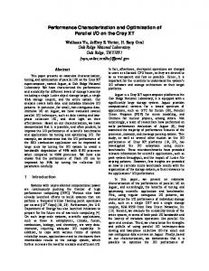
Commercially available tools, such as AMPS from Synopsys, optimize design at the transistor level by optimizing transistor cell netlists, while Cadabra provides an Automated Transistor Layout (ATL) tool that removes the layout bottleneck and thus enables rapid creation of custom cells.
Design rules Architecture
Automated Transistor Layout
GDSII Layouts
Combining the transistor netlist optimization of AMPS and the ATL migration and creation, Cadabra and Synopsys have jointly developed the Power and Performance Optimization (PPO) flow. This flow is a methodology that improves cell-based design by optimizing the standard cells within a design.
Figure 1: Automated Transistor Layout Creation Cell layout has to respect some specific guidelines. The created layout must follow the design rules of the targeted foundry. To be used in traditional place-and-route tools where cells are placed next to each other in rows, the cell layout must also comply with a common architecture, and the place-and-route tool requirements. ATL provides a high level of flexibility for the user to control the architecture and routing styles, and supports requirements for most advanced design rules and place-and-route tools.
2.
Automated Transistor Layout (ATL) 2.1. Traditional Cell Design Cell libraries usually are often developed by specialized library design groups in semiconductor companies or by library vendors. These cell designs are usually done in three main steps: Layout, verification and characterization/model generation. Traditionally, the cell layouts are designed by hand and then checked with commercially available physical verification tools such as DRC, extraction and LVS. Internal tools or commercially-available tools, such as CellRater from Silicon Metrics, often characterizes the cells and generates the timing and power models required by traditional EDA tools, such as synthesis, simulators and timing verifiers. This methodology makes library development very costly, time consuming and restricted to dedicated teams.
Once the architecture and layout style has been specified, ATL does not require any individual setup for each cell. It analyzes the Spice netlist connectivity, defines the optimal transistor folding and placement, and routes the internal nets of the cell following the layout style preferences. Finally, the two-dimensional compaction creates the LVS and DRC correct layout of the optimized cell. ATL is the result of years of experience and R&D at Cadabra and has been in production use at major semiconductor companies and library vendors since 1996.
2.2. Automated Cell Creation In contrast, some companies provide automated solutions for library development, thus enabling their customers to create better IP by starting from the foundation of their IP design flow: the cell library.
When it is determined that additional functionality is needed for the IP block, designers can quickly add cells, even if it is late in the design process. Because ATL does not require a specific set-up for each cell, specific cell creation is fast and easy. Creating 100 cells or 1000 cells requires almost the same effort. Moreover, the library design with ATL can
An ATL methodology creates fast, reliable and handcrafted-quality standard cell layouts. With ATL, designers complete the cell library in a fraction of the time required to manually layout
156
existing cell layouts to create new libraries and accommodate significant changes in process, transistor size and cell architecture.
easily be distributed across several workstations or computers. 2.3. Cell Migration ATL-based migration accommodates process technology changes such as retargeting to a new foundry, implementing the next generation technology, or implementing ECO changes, such as design rule revision. So whether an engineer designed his/her library with an ATL methodology or manually created the layout, ATL migration offers powerful re-use capabilities to accommodate changes in design rules, foundry or process technology. ATL migration can accommodate process changes that have a nonlinear relationship. Spice Netlists
Design rules Architecture
3. Transistor- Sizing Tool A transistor-level optimization tool, such as Synopsys AMPS, resizes the transistors in the cells depending on their configuration in the design to either meet timing goals or improve on them, while reducing power consumption. Synopsys AMPS reads in the standard cell Spice netlists, the design netlist, the design parasitic data and the timing constraints. It analyzes actual timing with its embedded transistor-level static timing analysis tool and then resizes the transistor size. AMPS' optimization does not change the circuit design but up- and downsizes the transistors to find the best cell depending on its context (i.e. output load, part of the critical path, driving cell, etc).
GDSII Layouts
Automated Transistor Layout
NOR20(u2745) i0 i1
INV1
1.68
o
1.68
0.42
i1
GDSII Layouts
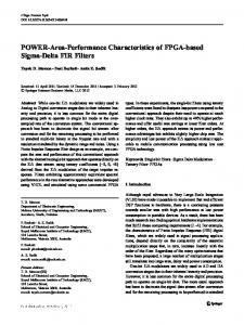
Figure 2: Automated Transistor Layout Migration
i0
In contrast, traditional compaction-based migration, where polygonal shape manipulation is the norm, the user is limited to simple manipulation of the input shapes, which can only accommodate minor process rule changes.
i1
i
INV1_1
1.68
ATL migration starts with an existing cell layout, usually in the GDSII format. It provides the ability to extract existing layout shapes that comprise structures such as transistors, wires, ports and diodes and re-create them automatically in the internal database as devices. The layout is then represented as a collection of devices rather than a collection of shapes. Therefore, it provides the ability to implement constraints and once inside the device database these objects can have inherent properties and constraints associated with them empowering an extended set of behaviors. A contact device, for example, could define the “behavior” that it should provide as many contact cuts as possible for a non-silicided process, with a “constraint” of not less than two. This allows users to leverage
i1
0.42
i1
0.42
NOR20(u2728) i0
1.68
i1
1.68
0.62 o
1.68
0.42
1.68 o
0.42
i i0
1.68
i1
0.42 i0
NOR20(u2745)
i0
0.84 o
i0
NOR20(u2728)
o
0.6 i0
0.42
i1
0.42
Figure 3: Critical Path optimization by transistor up and down sizing Figure 3 illustrates how a transistor-sizing tool creates the right cell within its configuration. In this example, the highlighted critical path goes through the falling edge (Transistor N) of the inverter. The speed of the signal going through this inverter can be increased by up-sizing the Transistor N to provide a drive strength of 1.5X on the falling edge. At the same time, the transistor P can be downsized to 0.5X because it does not belong to the critical path. This also reduces gate capacitance viewed by the gate driving the signal through the inverter, thus increasing speed and reducing power. The result is that the transistor-sizing tool automatically
157
optimizing the standard cells in the context of the design.
defines optimal transistor sizes. It adjusts the P/N ratio of each individual transistor pairs based on the configuration of each cell. To do so, it takes into account the post-layout wire capacitance, input slopes and the criticality in timing and power of these transistors and considers whether or not they belong to the critical path. The minimum and maximum P/N ration is also constrained in order to preserve cell integrity, as explained in section 7.
With the PPO flow, the design goes through one additional optimization phase at the transistor level. The original design block feeds into a design optimization at the transistor level. The transistor-sizing tool automatically resizes the standard cell transistors to determine the best combination that meets power and speed goals, resulting in new cells. The layout views of these new cells are then created using ATL. Once the optimized cell layout is completed, the original design is updated through ECO place-and-route to produce the optimized design.
Note that multiple instances of the same cell may produce in different optimized versions. AMPS' hierarchy management maintains the original netlist hierarchy and thus keeps the notion of a cell. This enables the cell to re-enter the gate level design flow.
5. Cell Layout To propagate the optimization to the original library and design, layout views of optimized cells need to be created. ATL was used to read AMPS's output of the Spice netlist and create optimized cell layouts in the same architecture as the original library. ATL offers two paths to implement the optimized cells: Migration and creation. Migration is used when the transistor size can be applied directly to the original cell layout. In that case, ATL reads the optimized netlist and the original layout. In order to minimize the perturbation introduced by the optimized cells in the placed and routed block, ATL derives footprint information, such as pin location and porosity from the original layout. When applying the new transistor sizes to the original layout, ATL tries to preserve the footprint of the original layout, as shown in figure 5.
To avoid data explosion, the transistor-sizing tool limits the number of cell variations. The result of transistor sizing is a new design netlist containing optimized cells that were not a part of the original cell library. 4. PPO Flow As Figure 4 shows, PPO flow starts from a design implemented with traditional cell-based design flows. The design is implemented with gate-level tools such as synthesis, placement and routing using an existing standard-cell library. This library can be created with ATL, but this is not a requirement. The result of the cell-based implementation is the original design, physical assembly of inter-connected standard cells. Beyond the optimization provided by gate-level design techniques, further power and performance improvements is achieved by 1-Traditional implementation: Synthesis P&R
2-Transistor Sizing
3-Cell Layout
4-ECO P&R
Original Layout PPO Flow
Locked Optimized Footprint Layout Figure 5: Cell Layout
However, it is not always possible to accommodate the new transistor sizes in the original layout. This is particularly evident when
Figure 4: PPO Flow
158
PPO-views require a layout analysis. We used ATL to run the layout analysis and to create these views automatically. PPO-views includes three main types of data: • Special cell declaration: The AMPS' statictiming engine requires some special definitions, such as latch-cell declarations. AMPS includes some automatic recognition of latch structures but some complex sequential elements require a user declaration. Other cells with specific structures, such as bus repeater, clock drivers, require some specific declaration too. • Electrical data: To preserve the electrical integrity of the cell during sizing, some sizing constraints are required. For instance, transistor sizing are usually constrained with Min/Max P/N ratio. Some transistors of the sequential elements are also constrained to preserve the memory behavior. • Topological data: To minimize the perturbation in cell footprints during layout of the sized cells, AMPS is usually constrained to keep MOSFETs within a certain range. This constraint is Min and Max size for each MOSFET of the cell.
doing performance optimization, where some transistors may grow too large to fit in the existing cell architecture without being folded. In that case, the optimized cell layout cannot be derived from the original layout anymore. For these cells, we used ATL in creation mode. 6. ECO Place-and-Route Once the optimized cell layout is created, the optimized design is loaded in the Place-andRoute tool in ECO mode. Final performance and power verification are performed at the transistor level with the final optimized design data. In general, ECO Place-and-Route can only accommodate minor changes in the design. If the perturbation in the block layout is important, rerouting may change the wire parasitics significantly and the convergence of the flow is no longer guaranteed. In the case of PPO, however, the design netlist and connectivity stay the same. Block routing changes may only come from cell placement changes due to an area increase of some cells. Cell area would only change if the transistor sizes changed significantly. In order to prevent that side effect, a setup phase analyzes the cell of the original library and derives the constraint for the transistor sizing tool to limit the change in cell area, as described in next section. 7. Library Analysis The PPO flow requires some preliminary setup. This setup phase has two main objectives: • Provide the specific cell setup data to the transistor optimization tools • Constrain the transistor sizing to preserve the cell behavior and try to control the impact of sizing on the cell area in order to minimize the cell footprint, and minimize the perturbation during ECO place-and-route after optimization
7.1. Special cell declaration Synopsys AMPS requires special cell declaration for latches in order to identify sequential elements, correctly analyze the timing through these elements and perform timing checks. If a cell declaration is not supplied for a latch, AMPS treats the latch as combinational logic. Cells declaration contains declarations that identify transistors that latch data, and feedback transistors to ignore. M 12,13,14,15
net52
I1
M 5,6,7,4
Prior to PPO, the analysis of the standard cell library used to implement the original design is mandatory to provide the needed data for the PPO flow. This is called PPO-views for the data and PPO-ready library for a library which has been analyzed and for which the PPO views are available. This analysis is not design dependant and is run only once for a standard cell library. PPO-views include cell-specific data.
M 22,23,17,18
net55 M 10,11
net46 net85
M 19,20, 24,25
I2
net71
O2 M 28,29 M 16,21 M 26,27
net73 M 8,9 M 30,31
Figure 6: Sequential element example For AMPS, the latch declaration of the register cell DFF shown in figure 6 is as follows:
PPO-views are commands for the transistoroptimization AMPS. Some PPO views must be specified by the library designer. The rest of the
subckt DFF latch \ latch_node=net52 \ latch_out=net55 \
159
O1
forward_devices=M10, M11 \ backward_devices=M12, M13, M14, M15\ subckt DFF latch \ latch_node=net85 \ latch_out=net46 \ forward_devices=M16, M21 \ backward_devices=M17, M18, M22, M23
This clock buffer cell is composed with 2 circuits: the dual-phase clock generation and output buffers, as shown in figure 7. The clock generation is a sensitive circuit than should not be resized by the transistor-sizing tool. On the other hand, the output buffers can be up or downsized in a certain range (in that case + or – 50%) without impacting the cell behavior.
subckt DFF non_transparent_node net55
Some other special cells, such as bus repeater are not suitable for sizing and sizing can be prevented by ignore_instance, no_touch commands. These special cell declarations are library specific and are usually provided by the library designer.
The AMPS constraint file for the clock buffer is then: subckt clkbuf set_no_touch M3*, M4*, M50 subckt clkbuf rel_tx_width_min .5 M1*, M2* subckt clkbuf rel_tx_width_max 1.5 M1*, M2*
7.2. Electrical integrity constraints It is recommended that all the critical circuits of the design should be constrained in order to preserve the electrical integrity of the cell during sizing. Here are a few examples of such sizing constraints: • Minimum and Maximum P/N ratio • Transistor pair N/P may also be constrained to keep the same ratio. • For sequential elements, the transistor-sizing tool is not allowed to change the transistor sizes of the latch core cells.
Clk
Dual-Phase Clock Circuit M30-50
Phi1 M11 M13 M21
Phi2
M23
Figure 7: Clock buffer cell example These electrical integrity constraints are library specific and are usually provided by the library designer. 7.3. Topological data The objective of the topological constraints is to minimize the perturbation in cell footprints during layout of the sized cells. Thus, AMPS is constrained with a Min and a Max size for each transistor of the cell. The ultimate minimum size is the minimum transistor size defined by the technology. However, it is not always possible to keep the same cell size when downsizing all the transistors to this minimum value. For instance, minimizing a transistor below the contact size may increase the cell size. As shown in figure 8, the diffusion-gate spacing increases the contactto-contact distance.
subckt DFF set_no_touch MU4* MU121 MU122 MU122 MU124 MU7* MU6* MU8*
• It is also not recommended to up-size other transistors of latch cells, such as clock drivers, output buffers, as it may impact the behavior of the core. subckt DFF rel_tx_width_max 1 MU*
subckt DFF latch\ latch_node=N1N244 latch_out=TP7 \ forward_devices=MU4* \ backward_devices=MU121,MU122,MU122,MU124 subckt DFF latch\ latch_node=N1N274 latch_out=N1N108 \ forward_devices=MU7*,MU8* \ backward_devices=MU6* subckt DFF non_transparent_node N1N274 subckt DFF set_no_touch MU4* MU121 \ MU122 MU122 MU124 MU7* MU6* MU8* subckt DFF rel_tx_width_max 1 MU* subckt DFF tx_width_min 0.42 MU132 subckt DFF tx_width_min 0.42 MU102
Figure 8: diffusion-gate spacing increases the contact-to-contact distance Another case where transistor downsizing may increase the cell width is when bent gates are used. When down-sizing a transistor with gate bends, the transistor may become too small to allow a gate bend and the gate bend must be
Table 1: PPO view for Sequential element The library used in the design presented later in this paper includes a dual-phase clock buffer.
160
removed, thus spreading the contacts apart, as shown in figure 9.
8.
PPO Results 8.1. Design Description A real-life example of how a PPO flow works is based on an Hitachi bus controller, a high performance LSI SH chip with a 32-bit data bus and a 16-bit address bus, used in handheld PC, high-speed games, and data communications. This original block, a 12k gate equivalent representing about 70,000 transistors, was implemented with traditional cell-based methodology using a standard cell library designed with ATL in an Hitachi 0.35um process. This design included 178 different cells. 8.2. Design Optimization
Figure 9: Gate bend removal increases contact-to-contact distance Defining the Min and Max sizes of each individual transistor requires a sophisticated analysis of the layout, which is provided by the PPOViewGen setup of CLASSIC-SC. PPOViewGen operates as follows: • Import the original layout of the cell in CLASSIC-SC. • Lock the footprint: cell width fixed to the original cell width; all valid hit points on pins are defined as ports; shapes are added to preserve all valid over-the-cell routing resource. • Compact the cell with an objective to minimize all the sizable MOSFETs. The design step reads the latch declaration PPO view to define which MOSFETs are sizable or identifies them automatically. • Export the PPO view: Final size of each sizable MOSFET is exported as an AMPS configuration file, as shown in table 1.
Mode: Slack-Driven, Slack Margin: 0.000 ns up=30.00u low=0.80u grid=0.01u wire=0 toggle=2 size_level=tx Number of txs = 70456 s_power slack tx_width [s_power slack width ] (mW) (ns) (um) (change in %, delta_slack) Initial:0.00000 -2.214 210373.6 [ 0.00% 0.00 0.00%] 1 th : 0.00000 -1.296 210646.3 [ 0.00% 0.92 0.13% ] 2 th : 0.00000 -0.584 210247.3 [ 0.00% 1.63 -0.06% ] 3 th : 0.00000 -0.327 209942.0 [ 0.00% 1.89 -0.21% ] 4 th : 0.00000 -0.151 209659.6 [ 0.00% 2.06 -0.34% ] 5 th : 0.00000 -0.390 209009.8 [ 0.00% 1.82 -0.65% ] 6 th : 0.00000 -0.117 209275.4 [ 0.00% 2.10 -0.52% ] 7 th : 0.00000 -0.016 209498.6 [ 0.00% 2.20 -0.42% ] 8 th : 0.00000 -0.195 208981.0 [ 0.00% 2.02 -0.66% ] 9 th : 0.00000 -0.020 209628.9 [ 0.00% 2.19 -0.35% ] 10 th : 0.00000 -0.011 209717.9 [ 0.00% 2.20 -0.31% ] 11 th : 0.00000 -0.158 209200.3 [ 0.00% 2.06 -0.56% ] 12 th : 0.00000 0.183 209787.5 [ 0.00% 2.40 -0.28% ] 13 th : 0.00000 -0.014 190357.0 [ 0.00% 2.20 -9.51% ] 14 th : 0.00000 0.154 190281.4 [ 0.00% 2.37 -9.55% ] 15 th : 0.00000 0.083 172540.3 [ 0.00% 2.30 -17.98% ] 16 th : 0.00000 0.008 157046.5 [ 0.00% 2.22 -25.35% ] 17 th : 0.00000 -0.076 156656.8 [ 0.00% 2.14 -25.53% ] 18 th : 0.00000 -0.423 156605.7 [ 0.00% 1.79 -25.56% ] 19 th : 0.00000 -0.327 156398.9 [ 0.00% 1.89 -25.66% ] 20 th : 0.00000 0.068 156789.7 [ 0.00% 2.28 -25.47% ]
AMPS optimized the more than 70,000-transistor design in about 10 hours on a Sun Microsystems Ultra 60 workstation with 512MB of memory. We chose the 20th iteration, which represents the best timing improvement.
In case of power only optimization, AMPS can be constrained to not grow any MOSFET. In that case, the maximum MOSFET size is the original size. Leaving more flexibility in sizing might help the optimization, and in that case the maximum size must be computed with a similar approach to the one used for computing the minimum size.
The original design's worst critical path was 18.5 ns. AMPS optimized the worst critical path to 16.02 ns, which compared to the original performance, represents a 13.5% improvement. In order to estimate the impact of sizing on power dissipation, we measured with PowerMill, the power of the design before and after optimization. PowerMill reported that the optimized was lowered by 18%.
The library analysis is run only once for a standard cell library; subsequent design optimizations with the PPO flow do not require this analysis to be run again. This step is critical for the convergence of the flow as it minimizes the ECO layout perturbation. It also controls the transistor sizing to preserve the electrical integrity of the optimized cells.
Slack Longest Path Idd
Original Design -2.214 18.5Ns 20mA
Optimized design +0.178 16.02Ns 16.4mA
Improv ement 13.5% 18%
To achieve that improvement, AMPS requested 300 optimized cells to be created, changing 22%
161
of the transistors in the design. Of those, 70% of the transistors were downsized and 30% were upsized. 8.3. Cell creation Among the 300 optimized cells required to implement the optimized design, 187 were created by ATL migration in about 10 hours, for an average of 3 minutes, 12 seconds per cell. Because the goal was optimizing performance, about 30% of the optimized cells required layout creation from the Spice using ATL creation with an average of 42 minutes per cell. Creating cell layout was parallelized, using a pack of 10 licenses. Because all the steps were automated, one iteration of the PPO flow on this 12k-gate design was completed in less than a day. 9. Conclusions Armed with twin capabilities of migration and creation, ATL can address the two demanding requirements of PPO. The migration capability fully exploits the strengths of symbolic migration, providing the fast turnaround times needed for most cells. The creation capability creates layout for cells that need to grow. Combining transistor sizing and cell creation, PPO increased performance by 13.5% and reduced power consumption by 18% in a 70,000transistor bus controller design, optimizing 300 cells of which 187 new cells were created. Because all the steps were automated, an iteration of the PPO flow on this design was completed overnight. PPO flow delivers higher performance and reduces the power consumption of cell-based designs. By offering more optimization than traditional cell-based designs, PPO is especially well suited for semi custom designs and hard IP development where high performance and/or low power are critical, and where transistor level optimization is more frequent than in ASIC design. PPO combines the efficiency of cell-based design and the accuracy and optimization of custom design, thus reducing the performance gap between ASIC and custom design.
162