Power Factor Correction With Vehicle-to-Grid STATCOM Implementation Anton Rassõlkin, Ants Kallaste, and Hardi Hõimoja
stability, and for application under power system faults; and it is also used as hybrid controllers in combination with passive elements [1]. Nowadays the most used charging devices for EV/HEV are unidirectional, that means they allow having power flow from grid to the vehicle battery, but many research institutions are trying to apply bidirectional charging devices, with battery to grid power flow [2]–[5]. Some solutions have the battery, or some other energy source, like supercapacitors or flywheels, included directly in the charging stations [6]–[8] or UPS systems [9]. Usually supercapacitors in EV/HEV applications are used as hybrid energy sources together with other energy storage devices. In comparison with batteries the charging/discharging times of supercapacitors are significantly shorter, which makes them an ideal solution for the devices that use electric motors to smooth the start-up current and voltage peaks. Battery energy storage system (BES) has the following features: modularity, environmentally benign, high efficiency, quick response [10]. In that case using EV/HEV batteries could be reasonable. The ratio of the real power flowing to the apparent power in the circuit called power factor shows the amount of useful power transferred in an electric power system. With a power factor close to 1 the real power flow is highest and the grid does not contain reactive currents. The higher reactive currents increase the energy lost in the power system, and require larger wire cross section and other equipment, what increase the cost of full system. Different devices are used for power factor correction. Тhe main principle of compensating device to produce the reactive current, that is opposite to reactive current source. Power factor compensating device needed to be putted as close as possible to the reactive power source to absorb reactive power near the load.
Abstract—The paper describes the connection of an electric vehicle to the utility grid and using the vehicle as a part of it. A new topology is presented and verified with experimental and simulation results. The experimental schematic allows to correct power factor of the grid, by using the part of the vehicle traction system. Basically it presents a portable STATCOM solution with a battery or hybrid energy storage system. By implementing the vehicle-to-grid conception, the EV/HEV become a part of the electric grid, bringing new features and benefits. Ability to use plug-in vehicles allows making the electric grid more “smart”. With more powerful vehicles, such as trucks or locomotives, the portable power solutions could be achieved. Results presented in paper are theoretical and experimental proof of upgrade possibilities of EV/HEV infrastructure and on-board architectures. There is no complex modernization required for plugging the EV/HEV to the grid. Moreover, the present powertrains can be updated. Index Terms—automotive applications, electric vehicles, power quality.
I. INTRODUCTION With growing numbers of electric vehicles (EV) and hybrid electric vehicles (HEV), they become a part of the utility grid. EV/HEV consumer role is changing to the smart consumer role, or so-called prosumer (combined producer and consumer device). Prosumer can become a part of electrical grid in different ways, there are two main solutions – as a usual consumer, when the EV/HEV is plugged into the charging point and consumes power from the grid; or as a buffering energy storage element, where the battery of EV/HEV is used as an energy storage device for energy exchange between the elements of distributed energy grid. Additionally there is the possibility to use EV/HEV as a smart producer for power quality improvement in grid. The scheme suggested in this paper can be used as static synchronous compensator (STATCOM) as the part of traction system of the EV/HEV. Fast acting STATCOM is a part of flexible AC transmission systems (FACT) device family. STATCOM is a promising technology being extensively used as the state-of-the-art dynamic shunt compensator for power quality improvements, reactive power control, voltage regulation, power swings/oscillations damping, damping torsional oscillations/sub-synchronous resonance damping, transmission line capacity enhancement, dynamic stability improvement including steady state, transient and voltage
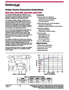
II. STATE OF THE ART To impose less current on the cables, the load must be seen predominantly active from the grid’s viewpoint, meaning the reactive power must be effectively compensated with power factor near to unity. Manufactures of the charging devices are trying to keep the power factor during the charging as high as possible [11] by using specific control algorithms, but some test results shows that during the different charging modes the power factor varies. Power factor timing diagram of Nissan Leaf on Fig. 1 shows that the power factor varies during fast and medium charging modes. During the fast charging phase (state of charge from 50% to 85%), time slice 0.0 s to 0.25 s, charging current was in the level of 29 A and the power factor almost unity. But under the medium charging phase (state of charge from 85% to 99%), time slice 0.25 s to 1.00 s, charging current was decreasing down to zero and the power factor was significantly below 1.
This research work has been supported by Estonian Ministry of Education and Research (Project SF0140016s11) and European Social Fund (project “Doctoral School of Energy and Geotechnology II”) A. Rassõlkin, A. Kallaste, and H. Hõimoja are with the Department of Electrical Engineering, Tallinn University of Technology, Ehitajate tee 5, 19086 Tallinn, Estonia(e-mail:
[email protected],
[email protected],
[email protected]).
978-1-4799-5022-5/14/$31.00 ©2014 IEEE
1
Power Factor
1 0,9 0,8 0,7 0,6 0,5 0,4 0,3 0,2 0,1 0
DC/DC
VSC K1
MS SOC 50..85%
SOC 85..99%
K2
Fig. 2. Drivetrain topology for the STATCOM operation.
Time (hh:mm:ss) Fig. 1. Power factor varies during different charging modes of Nissan Leaf *. * The test was made in laboratory of power electronics and electrical drives at Tallinn University of Technology by workgroup of electrical drives and automation.
T1
D1
T3
D3
T5
D5
T2
D2
T4
D4
T6
D6
C1
As it can be seen from the experimental results, there is some power factor correction required, during some charging phases of EV/HEV. If there is a couple of EV/HEV plugged into the grid, some of them could be used as a STATCOM device. STATCOM has many interesting features such as high speed of response (sub-cycle), versatile controlling and operational characteristics, ability to implement controllers of low/medium/high MVA ratings, lowspace requirement, higher stability margins and so on [1]. STATCOM is based on the principle that a self-commutating inverter can be connected between three-phase AC power lines and controlled to draw mainly reactive current from transmission lines. The current can be controlled to be either capacitive or inductive and is almost not affected by the line voltage [12]. There are some different circuit configuration designs for STATCOM, but they generally have the same application principles. The STATCOM is based on a solid-state voltage source converter (VSC), implemented with an inverter and connected in a shunt with the power system through a coupling reactor [13]. The series reactor is connected in order to provide harmonic minimization and depends on the power of device. Typically the reactor is heaviest part of the STATCOM. With connecting the battery to DC link capacitor the STATCOM gets ability for active and reactive power compensation. As for EV, the series reactor’s functionality is taken over by the traction motor windings (Fig. 2). The DC/DC converter keeps the DC link voltage constant regardless of the battery’s state of charge. The star connection contactor K1 is for motoring and K2 for battery charging and power factor correction modes. The main benefit of STATCOM is that it provides much better performance of reactive compensation over the conventional static var compensator (SVC). Additionally the STATCOM benefits are: interface with a real power source; higher response to system changes; mitigation of harmonics; superior low-voltage performance [12]. The VSC in the drivetrain as the prerequisite for the STATCOM operation is shown in Fig. 3. The operation modes of STATCOM are presented in Fig. 4. As shown in, Fig. 4a, when the STATCOM operates in no-load mode the voltage magnitude USTATCOM is equal to grid’s voltage magnitude Ugrid. STATCOM operates in capacitive operation mode (Fig. 4b) when the voltage magnitude USTATCOM is higher than grid’s voltage magnitude Ugrid and the current through the coupling reactor Ixl becomes leading.
Fig. 3. A trivial VSC schema.
a)
USTATCOM=Ugrid USTATCOM Ugrid
b)
c)
USTATCOM>Ugrid
IXL USTATCOM
IXL
Ugrid
I·jXL
USTATCOM
I·jXL
USTATCOMUSTATCOM
UGRID=USTATCOM
Phase shift
Fig. 5b. Simulation results with uncompensated power factor.
AM
Fig. 5a. Simulation results with compensated power factor.
Fig. 5b shows the case when grid voltage is higher than STATCOM’s voltage. As it can be seen from the traces, decreasing the voltage for 20 V gives phase shift already on grid side for 17°. To verify test results the experimental setup was created. Principle diagram of the experimental setup is shown in Fig. 6. Two 3-phase energy sources were imitating the connection of STATCOM to the grid. For the first 3-phase energy source the frequency converter (Micromaster 440, 0,55 kW by SIEMENS AS) connected in series with stator winding of induction motor (AM) was chosen (SIEMENS 3Mot 1LA7090-4AA10-Z). The AM acts as series inductor which separates the two voltage sources and also filters the switching ripple in the inverter current [14]. The 3-phase synchronous generator (SG) was taken as the second energy source (SIEMENS Typ. 033.75-401). For the load 3-phase star-connected resistance was used. Both 3-phase energy sources had possibility to control the output voltage rms value and could be synchronized with the common AC-link. During the tests frequency converter was connected to the load, then synchronous generator was started as motor for
M
Grid
uFC Load uload
SG
MS uSG
Fig. 6. Principle diagram of experimental setup.
Experimental results in Fig. 7a are similar to PSIM model results shown in Fig. 5a and Fig. 7b resp. to Fig. 5b. It can be seen from the experimental test results that the power factor of the system can be controlled with a voltage variation of STATCOM, connected in common AC link. With the voltage control it is possible to control the load power factor where it can be either inductive or capacitive load mode.
3
Frequency converter + Inductor
[3]
Voltage Current
[4]
Current
Synchronous Generator
[5] [6]
Voltage
[7]
Fig. 7a. Experimental test results with compensated power factor.
[8]
Frequency converter + Inductor Voltage Current Phase shift Current
[9] [10] [11]
Synchronous Generator
[12]
[13]
Voltage
[14] Fig. 7b. Experimental test results with uncompensated power factor.
IV. CONCLUSION AND FUTURE RESEARCHES With heightened attention to EVs and plug-in HEVs there is a lot of talks of their influence on existing utility grid. The paper presents theoretical possibility to improve vehicle propulsion systems. Simple and quick solution for controlling power factor is suggested. Schematic was proved theoretically, with a PSIM model and practically, with an experimental setup. Both proofs shows that controlling of the voltage value of schematic have effect on load’s power factor. Power factor could be corrected in both directions (inductive and capacitance loads). Suggested scheme has all advantages of STATCOM apparatus, meaning that not only power factor correction could be done, but also asymmetrical load balancing, voltage control, active harmonics filtration and flicker mitigation. Using the windings of the propulsion motor instead of separate inductors brings economic benefits and reduce in the weight. For the future research the suggested scheme should be scaled to real vehicle. Also the possibility of connection of different vehicle types should studied, while light and heavy weight vehicles could have different influence on the grid. Also the schematic needs to be studied in more detail according to economic parameters (price, self-repayment) and performance (efficiency and power losses).
Tech. Univ. - Electr. Control Commun. Eng., vol. 2, no. 1, pp. 47–54, Apr. 2013. J. Escoda, J. Fontanilles, D. Biel, V. Repecho, and R. Cardoner, “G2V and V2G operation 20 kW Battery Charger,” in EVS27 International Battery, Hybrid and Fuel Cell Electric Vehicle Symposium, 2013, pp. 1–5. T. S. Ustun, C. R. Ozansoy, and A. Zayegh, “Implementing vehicleto-grid (V2G) technology with IEC 61850-7-420,” IEEE Trans. Smart Grid, vol. 4, no. 2, pp. 1180–1187, Jun. 2013. X. Yan, B. Zhang, X. Xiao, H. Zhao, and L. Yang, “A bidirectional power converter for electric vehicles in V2G systems,” in 2013 International Electric Machines & Drives Conference, 2013, pp. 254–259. B. C. Liu, K. T. Chau, D. Wu, S. Gao, and C. Liu, “Opportunities and challenges of vehicle-to-home, vehicle-to-grid technologies,” Proc. IEEE, vol. 101, no. 11, pp. 2409–2427, Nov. 2013. T. Korotko, M. Magi, K. Peterson, R. Teemets, and E. Pettai, “Analysis and development of protection and control functions for Li-Ion based prosumers provided by low voltage part of distribution substation,” in 2013 International Conference-Workshop Compatibility and Power Electronics, 2013, pp. 19–24. M. Becherif, M. Y. Ayad, D. Hissel, and R. Mkahl, “Design and sizing of a stand-alone recharging point for battery electrical vehicles using photovoltaic energy,” in 2011 IEEE Vehicle Power and Propulsion Conference, 2011, pp. 1–6. R. G. Lawrence, K. L. Craven, and G. D. Nichols, “Flywheel UPS,” IEEE Ind. Appl. Mag., vol. 9, no. 3, pp. 44–50, May 2003. C.-F. Lu, “Dynamic modelling of battery energy storage system and application to power system stability,” IEE Proc. – Gener. Transm. Distrib., vol. 142, no. 4, p. 429, Jul. 1995. ABB: Electric Vehicle Charging Infrastructure Terra multi-standard DC charging station 53. p. 2, 2014. A. Karami, “Optimal location of STATCOM for voltage security enhancement via artificial intelligent,” in IEEE International Conference on Industrial Technology (ICIT), 2006. ICIT, 2006, no. 2, pp. 2704–2708. A. Rassõlkin and H. Hõimoja, “Power quality application of hybrid drivetrain,” in International Conference on Electrical Systems for Aircraft, Railway and Ship Propulsion (ESARS’12), 2012, pp. 4–7. P. S. S. Sensarma, K. R. R. Padiyar, and V. Ramanarayanan, “A STATCOM for composite power line conditioning,” in Proceedings of IEEE International Conference on Industrial Technology 2000 (IEEE Cat. No.00TH8482), vol. 2, pp. 542–547.
BIOGRAPHIES Anton Rassõlkin was born in Tallinn, Estonia, on September 28, 1985. He received the B.S. and M.S. degrees in electric drives and power electronics from Tallinn University of Technology, Tallinn, Estonia, in 2008 and 2010, respectively. In 2010 received Dipl. Eng. (FH) degree in automatics from the University of Applied Science Giessen-Friedberg, Giessen, Germany. His main scientific interests lie in electric transportation. Since 2010 he is a Ph.D. student at Tallinn University of Technology. Ants Kallaste was born in Pärnu, Estonia in 1980. He received the B.S. and M.S. degree in electrical drives and power electronics from Tallinn Univercity of Technology, Tallinn, Estonia, in 2004 and 2006 respectively. In 2013 he defended his Ph.D. thesis devoted to electrical generators design and application in wind mills. At the present he is a research scientist in the Department of Electrical Engineering. His main scientific interest lie in electrical machine design and application. Hardi Hõimoja received the Dipl.Eng. degree in electrical engineering from Tallinn University of Technology, Tallinn, Estonia, in 1998. At the end of 2009 he defended the Ph.D. thesis devoted to energy efficiency estimation and energy storage calculation methods for traction applications. At the present time he is a researcher in the Department of Electrical Engineering. He has over 20 publications and owns a utility model in the field of electrical drives and power electronics.
REFERENCES [1] K. Al-Haddad, R. Saha, A. Chandra, and B. Singh, “Static synchronous compensators (STATCOM): a review,” in IET Power Electronics, 2009, vol. 2, no. 4, pp. 297–324. [2] M. Mägi, “Utilization of electric vehicles connected to distribution substations for peak shaving of utility network loads,” Sci. J. Riga
4