ELECTRONICS AND ELECTRICAL ENGINEERING ISSN 1392 – 1215
2012. No. 2(118) ELEKTRONIKA IR ELEKTROTECHNIKA ELECTRICAL ENGINEERING
T 190 ───────────────────── ELEKTROS INŽINERIJA
Power Factor Correction based on Fuzzy Logic Controller with Fixed Switching Frequency A. Kessal, L. Rahmani, M. Mostefai Laboratoire d’Automatique (LAS), Université Ferhat Abbas, Faculté de Technologie, Département d’électrotechnique, Sétif, Algeria.phone : +213790721151, e-mail:
[email protected]
J. Gaubert Laboratoire d’Automatique et d’Informatique Industrielle (LAII), ESIP, Université de Poitiers, France http://dx.doi.org/10.5755/j01.eee.118.2.1176
multiplications), load disturbance, etc [7]. Hysteresis current controller (bang-bang hysteresis (BBH) technique) has an advantage in coping with the time varying nonlinearity of switches in PFC pre-regulator, and it does not require an accurate mathematical model of the PFC pre-regulator when the controller is being designed [8]. Also this technique has an advantage of yielding instantaneous current control, which results in very fast response and increased switch reliability. However, it has a serious disadvantage in that the switching frequency of the boost switch fsw is not constant and varies in a wide range during each half cycle of the ac input voltage [9]. The switching frequency is also sensitive to circuit component values, design parameters and difficult for EMI filter design. The novel feature of the proposed method resides in the fact that unity power factor and nearly sinusoidal input current are obtained at constant switching frequencies [10]. Moreover, the method exhibits an instantaneous control of current, which results in very fast response and increased switch reliability. This paper presents a systematic design, digital implementation and experimental comparison, in first a PI and fuzzy logic controllers with a 100Hz notch filter for a voltage loop of the regulated dc voltage, then the standard hysteresis controller and redesign with some modifications for improved performance in the current loop. All these controllers are verified by detailed MATLAB/Simulink based simulations through the use of a continuous time plant model and a discrete time controller. Design is comprehensive in the sense that it accounts for sampling effects, computation delays, hardware filtering for antialiasing and software filtering for measurement noise reduction. Real-time implementation is done on an experimental test bench using the dSPACE DS1104 controller board. These controllers are experimentally compared for steady-state performance and transient
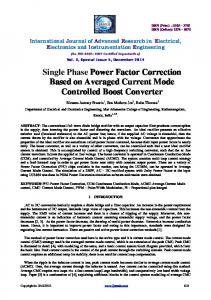
Introduction Single-phase power factor correction (PFC) circuits provide rectification of the line voltage to a regulated dc voltage while shaping the input current to be a sinusoid and in phase with the line voltage [1]. Often, the PFC acts as a pre-regulator to a dc–dc converter that may be used to provide additional regulation and ohmic isolation [2]. Due to adoption of IEC 1000-3-2 as the EN61000-3-2 norm in Europe and the formulation of the IEEE 519 [3] in USA, these circuits are increasingly being used in the front-end of electronic equipments. Among the several possible topologies[2], the boost PFC shown in Fig. 1 is most commonly used. The control objectives are to track the inductor current to a rectified Sinusoid (the line current is sinusoidal and in phase with the line voltage) and to regulate the average output voltage to desired magnitude with fast response to the load variation [4]. Recent research has been directed at applying nonlinear control principles to the dynamic control of converters. The system is controlled by fuzzy control algorithm, in which a set of linguistic rules written in accordance to experience and intuitive reasoning. However, if the control methodology is directly applied to classical ac-dc converters with APFC [5], it might impose considerable computation time to deal with the fast-varying current loop. Fuzzy logic control has been investigated for applications such as motor drives and dc-dc converters [6]. Objectives include tight output voltage regulation, high rejection of reference output voltage variations and load transients. The improvement in the transient response of the controller voltage loop decreases the quality of the input current (High THD). On the other hand, PI controller design in current loop requires an accurate mathematical model of the plant and it failed to perform satisfactorily under parameter variation, nonlinearity (two 67
response over the entire range of input and load conditions
for which the system is designed.
Fig. 1. APFC pre-regulator
controller consists of three basic blocks: Fuzzification; Inference Mechanism and Defuzzification
Voltage-loop controller PI-Controller. As shown in Fig. 2, the dc-bus voltage u0 is sensed and compared with a reference value ∗ . The obtained error is used as input for the PI controller, the output of the controller ∗ multiplied by |sin | obtained from PLL stage with sensing of the input voltage is the instantaneous reference current command iref.
Table 1. Design specification and circuit parameters Desired switching frequency fswd=20kHz Output power P0=121W Magnitude of supply voltage USM=150V DC-Bus reference output voltage U*0=160V Input current ripple ≤2,5% Output voltage ripple ≤2% Load resistance R=212Ω Input Inductance L=22,5mH Output Capacity C=940µF
Fig. 2. PI-Controller for APFC
is the transfer function of the PI-Controller; =
,
=
∗
Fig. 3. shows the block diagram of the proposed fuzzy logic control scheme of the boost rectifier with APFC. The dc-bus voltage is scaled and is sampled by the digital apparatus and compared with a reference value ∗ . The obtained error ( ) = ∗ ( ) − ( ) and its incremental ( ) = ( ) − ( − 1) at the kth sampling variation instant are used as inputs of fuzzy controller. The output is the variation magnitude of reference current ∗ . The dcbus voltage is controlled by adjusting the magnitude of reference current ∗ . Where ρ and σ are constants used to normalize the error and the change of error.
: are the PI parameters; fCV is the
voltage closed loop crossover frequency. The system in Fig. 1 is modeled as a first order system ∗
=
4
∗
1+
= 2
1+
.
(1)
Pole and gain are chosen to obtain a sufficient phase margin gain (≈45°) and bandwidth in the 5Hz to 20Hz range. The bandwidth is intentionally kept very low since the compensator gain at 100Hz effectively determines the third harmonic to be expected in the input current. Since the outer loop has a finite dc gain, the voltage reference is pre-compensated to avoid a steady state voltage error at nominal operation. With fCV=10Hz, Ki=2.0160 and Ti=0.0494, the closed loop transfer function with the design example given in table 1 is ∗
=
1+
=
16 , 1 + 0, O159
Fig. 3. Fuzzy logic-Controller for APFC
(2)
Table 2. Fuzzy control rules
The circuit is designed with the following specification (Table 1). Fuzzy Logic-Controller. The fuzzy logic controller unlike conventional controllers does not require a mathematical model of the system that should be controlled. However, a comprehending of the system and the control requirements is necessary. The fuzzy controller designer must clarify how the information is processed (control strategy and decision), and information flows out of the system (solution/output variable). The fuzzy logic
(Cεv)
68
NB NM NS ZE PS PM PB
NB NB NB NB NB NM NS ZE
NM NB NB NB NM NS ZE PS
NS NB NB NM NS ZE PS PM
(εv) ZE NB NM NS ZE PS PM PB
PS NM NS ZE PS PM PB PB
PM NS ZE PS PM PB PB PB
PB ZE PS PM PB PB PB PB
Current-loop controller −
The PFC circuit analyzed here has a feedback loop such that the switching mode is determined by comparison of the actual current and sinusoidal reference current supplied form voltage loop controller in both ways the actual current oscillates in fixed band hysteresis (FBH) as shown in Fig.4. In the second way, the actual current oscillates in variable band hysteresis (VBH).
∗
=
(10)
.
From (9) and (10) =
−
∗
(11)
,
where = − – the error current in hysteresis band, ∗ – the interrupter reference voltage. − ∗ constant From (11), if we assume the quantity during the switching period, then the error current ( ) varied as triangular form as shown in Fig. 5. and : From Fig. 6 and (11), become =
∗
,
= ∗
=
(
∗
−
−
∗
,
(12)
) .
(13)
Fig. 4. Switching frequency
From (11) and (13), switching frequency is =
(
−
ref )(
−
+
ref )
,
(14)
|sin ( )| , |sin ( )|. where = = To investigate the control characteristics of a PFC, the variation of maximal switching frequency (MSF) with the inductance L of ΔI parameter for FBH is evaluated in Fig. 6. Fig. 5. Current error and the switch H voltage
Conventional Hysteresis Current Control. In this scheme, the algorithm is given as: β
Upper band iupper =IrefM sin(ωt) +ΔI=IrefM sin(ωt) +( ), 2 Lower band(
lower )
=
refM
) − ΔI = β sin( ) + , 2
sin(
=
If
>
If