Power Management in External Memory using PA-CDRAM N. AbouGhazaleh* Department of Computer Science, University of Pittsburgh, Pittsburgh, PA, USA E-mail:
[email protected] *Corresponding author
B. R. Childers Department of Computer Science, University of Pittsburgh, Pittsburgh, PA, USA E-mail:
[email protected]
D. Moss´ e Department of Computer Science, University of Pittsburgh, Pittsburgh, PA, USA E-mail:
[email protected]
R. G. Melhem Department of Computer Science, University of Pittsburgh, Pittsburgh, PA, USA E-mail:
[email protected] Abstract: Main memory has become one of the largest contributors to overall energy consumption and offers many opportunities for power/energy reduction. In this paper, we propose a new memory organization, called Power-Aware Cached-DRAM (PA-CDRAM), that integrates a moderately sized cache directly into a memory device. We use this cache to turn a memory bank off immediately after a memory access to reduce energy consumption. While other work has used CDRAM to improve memory performance, we modify CDRAM to reduce energy consumption. In this paper, we describe our memory organization and describe the challenges for achieving low energy consumption and how to address them. We evaluate the approach using a cycle accurate processor and memory simulator. Our results show that PA-CDRAM achieves an average 28% improvement in the energy-delay product when compared to a traditional memory employing time-out power management technique. Keywords: Memory power management, cached DRAM.
1 INTRODUCTION
Energy consumption is a limiting constraint for both embedded and high performance systems. In embedded systems, the lifetime of a device is limited by the rate of energy dissipation from its battery. On the other hand, energy consumption in high-performance systems increases thermal dissipation, which requires more cooling resources, and has a higher system management overhead. In general, the memory subsystem is considered one of the major energy consumers in computing systems (Celebican et al., 2004). With the increasing variety of applications that re-
quire high memory capacity, a significant increase in the amount of energy consumed in accessing data is expected, which motivates the need for memory energy management schemes. Memory has a huge internal bandwidth compared to its external bus bandwidth (Elliott et al., 1992). To exploit the wide internal bus, cached DRAM (CDRAM) adds an SRAM cache to the DRAM array on the memory chip (Hsu et al., 1993). The on-memory cache acts as an extra memory hierarchy level, whose fast access time improves the average memory access time and potentially improves system performance, provided that the on-memory cache is c 200x Inderscience Enterprises Ltd. Copyright
Row decoder
DRAM−core
row address
DRAM bank
column address
decoder
Sense Amplifier
cache Line address
Data in/out SRAM cache Column decoder
on−memory cache
Control logic
appropriately configured. In this paper, we explore the benefit of having onmemory cache with respect to its energy consumption. We optimize CDRAM by integrating a moderately sized cache within the chip boundary of a power-aware multibanked memory. We call this organization power-aware cached DRAM (PA-CDRAM). In addition to improving performance, PA-CDRAM can significantly reduce the energy consumption in external memories by powering off the DRAM banks after the data is transferred to the onmemory cache. We also show that PA-CDRAM is more energy efficient than using an extra level of off-chip cache of equal size. The remainder of this paper is organized as follows. Section 2 gives an overview of memory technologies and organizations that serve as the base for PA-CDRAM. Section 3 describes the challenges for designing power efficient CDRAM and the design approaches used in PA-CDRAM to overcome them. Evaluation of PA-CDRAM with respect to energy-delay product is presented in Section 4. Section 5 concludes the paper.
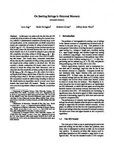
Figure 1: Functional block diagram of a CDRAM chip
2 BACKGROUND
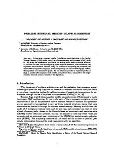
As background for the paper, this section describes the Figure 2: Average performance and energy reduction for technologies and organizations that serve as the basis for different on-memory cache block sizes. PA-CDRAM.
2.1
Embedded DRAM
Integrating DRAM and logic cells on the same chip is an attractive solution to achieve both high performance (from logic cells) and high memory density (from DRAM cells). This integration avoids the high latency of going offchip by doing computation (or even caching) at the memory itself. Currently, manufactured chips with embedded DRAM and logic are mainly used in applications like computer graphics, networking, and handheld devices (KeitelSchultz et al., 2001). Based on the fabrication technology (either DRAM-based or logic-based), some degradation to the speed (density) of the logic (DRAM) cells may occur. For example, in DRAM-based chips, logic cells can be slower by 20% to 35% (Keitel-Schultz et al., 2001). However, emerging fabrication technologies aim to overcome these penalties. For example, NEC’s embedded DRAM chips offer DRAM-like density with SRAM-like performance (NEC eDRAM, 2005), and IBM’s third generation embedded DRAM chips support two embedded DRAM families for high density and high performance (Tomashot, 2003).
2.2
Cached DRAM
chunks of data can be transferred between the DRAMcore and the on-memory cache with low latency. Average memory access time is improved by accessing the data through the fast on-memory cache rather than the slower DRAM. CDRAM is typically implemented using Synchronous DRAM (SDRAM) (Davis, 2000), and each memory bank has its own cache. While CDRAM improves system performance, it is not designed as a replacement for power-aware memory. Figure 2 shows the average1 performance and energy consumption of CDRAM versus a traditional memory hierarchy for the same on-memory cache configuration used by Hedge et al. (Hegde et al., 2003). Each CDRAM chip has a fully associative 4 KB cache. We show the results for different cache block sizes (256, 512 and 1024 bytes). While CDRAM has a good performance improvement over traditional memory, total memory energy suffers dramatically, with an increase of 1.5 times to 3.0 times. This increase is due to the extra energy consumed from accessing the on-memory caches and transferring more data from the DRAM-core at large block sizes.
2.3
Rambus Memories
Rambus (Rambus, 2005) is a family of DRAM architecTo decrease the average memory access time, Hsu et al. tures where the memory bus, the Rambus Channel, can (1993) proposed to integrate a small SRAM cache within operate at high frequencies (800-1600 MHz). As opposed the memory chip next to the DRAM-core, as shown 1 running the SPEC2000 benchmarks in Figure 1. Due to high internal bandwidth, large
to SDRAM technologies, a single RDRAM chip can service the entire memory request rather than distributing the request to several SDRAM chips. RDRAM chips dynamically transition between power states to reduce the chips’ energy consumption. A chip can be set in one of four different power states. The states, in descending order of their power consumption, are: active, standby, nap and powerdown. Accessing data requires the chip to be in the active state. The lower the power state of a bank, the longer the synchronization delay needed to switch to the active state to service a request.
3 PA-CDRAM
We optimize the CDRAM design to serve as a poweraware memory that is more energy and delay efficient than traditional power-aware memory systems. We use the CDRAM’s on-chip cache to reduce memory accesses to the DRAM-core; thus, increasing its idleness. We use this caching to allow the DRAM-core to be quickly transitioned to a low power state for longer time periods. In using CDRAM as the basis for PA-CDRAM, there are two main challenges that must be addressed: (1) how to configure the DRAM-core’s power management policy, assuming the use of multiple power states; and (2) how to configure the on-memory cache to balance energy and performance. We describe each of these challenges and how we address them below.
3.1
DRAM-core power management
To optimize CDRAM operation for energy savings, we need to minimize the number of active chips at any time as well as the duration of active periods. Bounded by the external memory bandwidth, CDRAM (using SDRAM) interleaves data blocks across multiple chips. At each memory request, n chips within a memory module are activated and each chip provides n1 of the block size requested. This interleaving of data blocks entails overhead in address decoding, and bit-/word- line activation in more than one chip. Thus, a more energy efficient organization would utilize chips that offer (a) an independent access to the DRAMarray and (b) full bandwidth utilization of the system bus to avoid reducing the memory throughput. The energy overhead is reduced by activating a single chip at each access, and performing fewer address decoding operations in the target chip during data retrieval. With an on-memory cache, we propose to apply aggressive power management in the DRAM-core to reduce the duration of active periods. During a chip’s idle time, the memory controller can immediately transition the DRAMcore to the sleep state after servicing all outstanding DRAM-core access requests. This is equivalent to the use of a timeout policy with an idle threshold of zero seconds. Although a zero-threshold policy increases the total inactive time, it can degrade performance and increase the total energy consumption when too many requests are di-
rected to a memory chip. The extra delay and energy overheads are due to the transitional cost between power states. In our PA-CDRAM design, we avoid this problem by choosing the on-memory cache configuration such that it delivers high hit rates while reducing the DRAM-core’s energy consumption. When most data requests are serviced as cache hits in the on-memory cache, the interarrival time between requests that reach the DRAM-core increases, making it cost effective to immediately deactivate banks after servicing outstanding requests. We choose to keep the on-memory cache in the active state all the time to avoid delays due to on-demand activation of the cache at each request.
3.2
On-memory cache configuration
The on-memory cache miss rate should be kept at a minimum as it directly influences the memory energy consumption (in addition to performance). The higher the miss rate, the more memory energy is consumed due to increased DRAM-core activity. This energy is consumed in transitioning from the sleep to the active state, performing address decoding, and transferring data. For a given cache size and a fixed number of cache subbanks, the two factors affecting the cache energy consumption and access latency are the associativity and the block size (Cacti, 2001). We used Cacti-3.0 to study a 256KB cache with respect to latency and energy consumption. Figure 3 shows the trend we observed: compared to n-way associative caches, energy and latency cost per access in a fully associative cache decreases at large block sizes, in contrast to small block sizes where full associativity is relatively expensive (in latency and energy). Although we only show the per-access metric for a 256 KB cache, other cache sizes with similar cachesize blocksize ratios follow the same pattern. To further examine this issue, we studied a memory with eight CDRAM chips. Each chip contains a cache of moderate size, 256 KB with 512 B cache blocks. Figures 4 and 5 show the effects of varying the associativity and the block size on the on-memory cache average miss rate of the eight chips. We use these results to motivate the selection of our on-memory cache configuration. The miss rates values are collected from the Simplescalar architecture simulator (Simplescalar, 2004) and correspond to a set of applications from the SPEC2000 (int and fp) benchmarks. Figure 4 shows that the higher the associativity, the lower the average miss rate across all caches until saturation is reached. Note that, in most of the tested benchmarks, the miss rates of the 8-way set associative caches are as low as the fully associative caches. However, from Figure 3, we see that the per-access latency and energy consumption of a cache with large block sizes (512B and larger) are lower in the fully associative cache than the 8-way cache. From these results, we use fully associative caches with relatively large block sizes as our PA-CDRAM cache configuration.
Figure 3: The effect of varying the cache block size and associativity on the cache’s per-access latency and energy consumption for a 256KB on-memory cache.
Figure 4: Effect of varying the associativity on the miss rate in caches with 512B blocks.
Figure 5: Effect of varying the cache block size on the miss rate in fully associative caches .
The performance of on-chip and external caches are constrained by the width of the system bus. To retrieve data from memory with small latencies, the size of the requested blocks are typically small (64 bytes for L2 and 128 bytes for optional L3 caches in some Pentium4 processors (Pentium 4, 2003)). In contrast, the on-memory caches do not have such a constraint because of the large internal memory bandwidth. Thus, large blocks of data can be transferred to the on-memory caches with low latency, which favors the use of large block sizes in PA-CDRAM. Figure 5 shows that on-memory caches with larger blocks have lower miss rates than caches with smaller blocks. With larger transfer sizes, there are fewer accesses to the DRAM-core. From the energy perspective, Figure 3 shows that for a fixed way-associative cache, accessing large blocks consumes more energy than accessing smaller blocks. However, the energy-per-byte for each access is lower in accessing large blocks. Although the miss rate and the per-byte cache access energy are reduced for large block sizes, there is a potential increase in the memory energy consumption if many unnecessary bytes are transferred between the on-memory cache and the DRAM-core. To achieve a balance between obtaining low miss rates and avoiding excessive memory traffic, we select a relatively large block size around 512B. This is different from the proposal of Koganti et al. (1997), which uses block sizes that range from 4KB to 8KB. The difference in our evaluation is that we take into account the energy consumption and delay for accessing the caches (L3 or on-memory). From Figure 3 we conclude that cached DRAM with wide cache lines– although it significantly reduces the average on-memory miss rate - is not energy efficient due to the extra energy consumed in accessing the on-memory cache compared to smaller block sizes in traditional memory hierarchy.
4 EVALUATION
To evaluate PA-CDRAM, we perform experiments using the Simplescalar architecture simulator (Simplescalar, 2004) with an integrated memory module (Gries et al., 2004). The simulated memory consists of eight chips, each of size 32 MB for a total 256 MB memory. Our study evaluates the energy consumption of PACDRAM against a base case that employs traditional power saving policies provided by the Rambus architecture. The base case contains on-chip L1 and L2 caches and an off-chip L3 cache. The size of an L3 cache in the base case is equal to the total size of all eight on-memory caches in PA-CDRAM. We compute the energy consumption in the DRAM-core, caches and busses. The timing and power characteristics of the simulated RDRAM chip are for the RDRAM 256Mb/1066MHz/32 split bank architecture (Rambus, 2005). Access energy and latency for each cache configuration is obtained using Cacti 3.0 for 130 nm. A delay penalty of 35% is added for accessing logic cells in the memory chip. In the evaluation, we validate the approach for
selecting the PA-CDRAM parameters by exploring different on-memory cache configurations and memory time-out thresholds for both the base case and the PA-CDRAM. We compare the different configurations of the onmemory cache and the DRAM time-out power management policy. We use the energy-delay product to show the most promising configuration across all the tested applications. Figure 6 shows the normalized energy-delay product at different cache configurations. Each data point is the average of 12 benchmarks. We experimented with many cache configurations: we show the ones with the best results for each memory model. In this result, we use the best memory timeout-threshold for each case (see below). In PA-CDRAM, an on-memory cache with a 512B block size compromise between overall delay and energy consumption. Blocks larger than 512B increase the onmemory cache access costs (both latency and energy) as described in Section 3. On the other hand, reducing the block size increases the DRAM core energy due to the increasing number of DRAM accesses. Similarly, in the base case, a block size of 128B balances energy consumption and overall delay. The figures also show that the best cache configuration in an external cache does not yield the best results when used for an on-memory cache (configurations shown as hashed bars) and visa versa. That is, an 8-way L3 cache with 128B blocks is 5 times worse than the 512B fully associative configuration in terms of energydelay product when used in on-memory caches, while the fully associative 512B configuration is 20% worse than the best L3 configuration. For the remaining results in this evaluation, we explore the benefit of using fully associative on-memory caches with a 512B block size versus an 8-way L3 cache with 128B blocks. As power management in the DRAM-core relies on increasing idle periods, PA-CDRAM can reduce the memory energy consumption by reducing caches’ miss rates. Reducing the on-memory cache miss rates lowers the number of DRAM accesses; thus, reducing the DRAM-core energy. Figure 7 shows the miss rates of L3 in the base case versus the average miss rates of the on-memory caches in PACDRAM chips. In all applications, PA-CDRAM reduces the miss rate. This reduction in miss rate is due to both larger blocks and higher associativity in the on-memory caches than in the large L3 cache. To show the effect of reducing the miss rate on the choice of proper timeout-policy for the DRAM power management, Figure 8 shows the normalized energy-delay product averaged over the tested applications at different timeout thresholds. The results are obtained for a base case with 128B blocks, 8-way cache and for PA-CDRAM with 512B blocks, fully associative caches. The best timeout for the base case is around 1000 cycles. However, for the PACDRAM, immediate deactivation of the DRAM-core after each access yields the best overall average energy-delay product. This verifies the result that using an on-memory cache allows aggressive deactivation of the DRAM-core for more efficient memory power management. From Figures 6 and 8, we find that lowest energy-delay
Figure 6: Average normalized energy-delay product at different cache configurations for base case (left) and PA-CDRAM (right). Data normalized to the base case.
Figure 7: Miss rates in L3 (base case) versus on-memory (PA-CDRAM) caches.
Figure 8: Average normalized energy-delay product at different timeout-threhold for base case (left) and PA-CDRAM (right). Data normalized to base case.
product in the base case is achieved by using an L3 8-way cache with 128B blocks and a timeout threshold of 1000 cycles. However, in PA-CDRAM, the best setting is when using fully associative on-memory caches of 512B blocks, and immediate DRAM shutdown. For the remaining of this paper we use these settings to obtain the rest of our results. We compare PA-CDRAM with a fully associative integrated CDRAM with wide cache lines,WCDRAM (Koganti et al., 1997). WCDRAM uses on-memory cache with very large cache blocks (between 1KB to 8KB) to minimize the on-memory cache miss-rates. We compare against WCDRAM with on-memory caches with 2048B blocks and the same capacity as in the base case (equals PA-CDRAM cache capacity). Figure 9 shows that WCDRAM is very inefficient in terms of energy-delay product because of the high energy consumption and latency of accessing the onmemory caches.
Figure 10: Total area occupied by L3 cache (base case) and all on-memory caches (in PA-CDRAM or WCDRAM) in case of 1T and 6T SRAM technology. ory organization, when set with appropriate cache and DRAM-core configuration, can achieve higher energy-delay savings than traditional memory hierarchy. When compared with WCDRAM, PA-CDRAM achieves higher savings in energy-delay product with smaller area overhead. Using the 1T-SRAM technology gives an advantage to PACDRAM over traditional memory organization in terms of the total area occupied by the memory.
5 CONCLUSIONS
Figure 9: Comparision of energy-delay product in PACDRAM and WCDRAM normalized to the base csae.
In this paper, we described a power-aware cached DRAM organization that reduces both energy consumption and overall delay. While cached DRAM has previously been proposed to improve memory access time, in this paper we explore the energy efficiency of power-aware cached DRAM as an alternative to a traditional power-aware memory. For this, we address the challenges and the tradeoffs between maximizing the performance and minimizing energy consumption, and we balance those trade-offs from the DRAM-core and the on-memory caches perspectives. There are many factors affecting energy consumption and performance of a PA-CDRAM memory system. Our evaluation shows that, on average, a fully associative on-memory cache with 512B blocks and memory with immediate transition to lower power state achieves the best energy delay product in the tested benchmarks. When compared to traditional memory using time-out power management, PA-CDRAM reduces the energy-delay product by 28% on average.
Furthermore, we compare the area overhead of having on-memory caches versus traditional L3 cache. Onmemory caches occupy smaller area based on the new 1TSRAM technology that creates an SRAM cell from one transistor rather than six transistors as in the 6T-SRAM technology used in traditional SRAM caches (Mosys Inc., 2005). Since the manufacturing process is different in both technologies, we approximate the area of the on-memory caches (for lack of an accurate way of estimating the area of embedded caches). First, we obtain the caches’ area from Cacti (6T-SRAM technology) for the corresponding cache configurations of each memory model. Then, we multiply the obtained cache area (of PA-CDRAM and WCDRAM) by the ratio of the size of single bit in 1T-SRAM to 6TSRAM (that is, 0.51/2.14=0.24 (Leung, 2005)). Figure 10 shows the total area occupied by caches: L3 cache (in base REFERENCES case) versus all (eight) on-memory caches (in PA-CDRAM or WCDRAM) in both technologies. Note that, we account for the potential delay (35% penalty) of accessing Celebican, O., Simunic Rosing, T. and Mooney, V. (2004) 1T-SRAM on-memory caches in our results as described ‘Energy estimation of peripheral devices in embedded earlier in this section; however, the base case suffers no systems’, GLSVLSI ’04: Proceedings of the 14th ACM delay penalties for using 6T-SRAM cache. Great Lakes symposium on VLSI, pp. 430–435, Boston, MA, USA. In summary, the results show that PA-CDRAM mem-
D. Elliott and W. Snelgrove and M. Stumm (1992) ‘Computational RAM: A Memory-SIMD Hybrid and its Application to DSP’, Proceedings of the Custom Integrated Circuits Conference pp. 30.6.1–30.6.4 Hsu, W. and J. Smith (1993) ‘Performance of cached DRAM organizations in vector supercomputers’, Proceedings of the International Symposium on Computer Architecture, pp. 327–336, San Diego, California, United States. Davis, B., (2000) ‘Modern DRAM Architectures’, PhD. Thesis, University of Michigan, Ann Arbor. Keitel-Schulz, D. and Norbert Wehn (2001) ‘Embedded DRAM development: Technology, physical design, and application issues’ , IEEE Transactions on Design & Test of Computers, vol. 18, No. 3, pp. 7-15. NEC Embedded DRAM(2005), http://www.necelam.com/edram90/
URL:
Steve Tomashot, ‘IBM embedded DRAM approach’, (2003), URL: http://www.ibm.com/chips/techlib/techlib.nsf/products/Embedded DRAM, Hegde, A., Vijaykrishnan, N., Kandemir M., and Irwin, M.J. (2003) ‘VL-CDRAM: variable line sized cached DRAMs’ Proceedings of the International Symposium on Hardware/software codesign & system synthesis, pp. 132–137, Newport Beach, CA, USA. Rambus Inc. (2005), ‘Products Data Sheets’, URL: http://www.rambus.com/products/rdram/documentation. Shivakumar, P. and Jouppi, N., ‘CACTI 3.0: An Integrated Cache Timing, Power, and Area Model’, Technical report no. 2001.2, Compaq research labs. Simplescalar architectural simulator http://www.simplescalar.com.
(2004),
URL:
Intel Pentium 4 EE processor (2003), URL: http://www.intel.com. Koganti, R. and Kedem, G. (1997), ‘WCDRAM: A Fully Associative Integrated Cached-DRAM with Wide Cache Lines’, Technical Report, Department of Computer Science, Duke University. Gries, M. and Romer, A. (2004), ‘SDRAM and RDRAM modeling for Simplescalar simulator’, Computer Engineering Research Group , URL: http://www.tik.ee.ethz.ch/˜ip3/software/simplescalarmem model.html. Mosys, Inc. (2005), ‘1T-SRAM http://www.mosysinc.com.
Products’,
URL:
Leung, W. (2005), ‘I need more memory: Do I trench or do I stack?’ presentation in the 3rd International System-on-Chip Conference, Mosys Inc., URL: http://www.mosysinc.com/corp/pdf files/pdf/soc1005.pdf.