Jul 14, 2012 ... Neural Network Principal Component Analysis, Harmonic ... This paper describes
a new approach for power transformer differential protection ...
Hindawi Publishing Corporation Advances in Artificial Intelligence Volume 2012, Article ID 930740, 9 pages doi:10.1155/2012/930740
Research Article Power Transformer Differential Protection Based on Neural Network Principal Component Analysis, Harmonic Restraint and Park’s Plots Manoj Tripathy Department of Electrical Engineering, Indian Institute of Technology Roorkee, Roorkee 247 667, India Correspondence should be addressed to Manoj Tripathy, manoj tripathy1@rediffmail.com Received 8 May 2012; Accepted 14 July 2012 Academic Editor: Deacha Puangdownreong Copyright © 2012 Manoj Tripathy. This is an open access article distributed under the Creative Commons Attribution License, which permits unrestricted use, distribution, and reproduction in any medium, provided the original work is properly cited. This paper describes a new approach for power transformer differential protection which is based on the wave-shape recognition technique. An algorithm based on neural network principal component analysis (NNPCA) with back-propagation learning is proposed for digital differential protection of power transformer. The principal component analysis is used to preprocess the data from power system in order to eliminate redundant information and enhance hidden pattern of differential current to discriminate between internal faults from inrush and overexcitation conditions. This algorithm has been developed by considering optimal number of neurons in hidden layer and optimal number of neurons at output layer. The proposed algorithm makes use of ratio of voltage to frequency and amplitude of differential current for transformer operating condition detection. This paper presents a comparative study of power transformer differential protection algorithms based on harmonic restraint method, NNPCA, feed forward back propagation neural network (FFBPNN), space vector analysis of the differential signal, and their time characteristic shapes in Park’s plane. The algorithms are compared as to their speed of response, computational burden, and the capability to distinguish between a magnetizing inrush and power transformer internal fault. The mathematical basis for each algorithm is briefly described. All the algorithms are evaluated using simulation performed with PSCAD/EMTDC and MATLAB.
1. Introduction Power transformer is one of the most important components in power system, for which various types of protective and monitoring schemes have been developed for many years. Differential protection is one of the most widely used methods for protecting power transformer against internal faults. The technique is based on the measurement and comparison of currents at both side of transformer: primary and secondary lines. The differential relay trips whenever the difference of the currents in both sides exceeds a predetermined threshold. This technique is accurate in most of the cases of transformer internal faults however mal-operation of differential relay is possible due to inrush currents, which result from transients in transformer magnetic flux. The transients in transformer magnetic flux may occur due to energization of transformer, voltage recovery after fault clearance or connection of parallel transformers.
The existence of such current disturbances has made the protection of power transformers a challenging problem for protection engineers. Therefore, accurate classification of currents in a power transformer is need of this challenging problem, in preventing maloperation of the differential relay under different nonfault conditions including magnetizing inrush, over-excitation, external fault, and saturation of current transformers [1]. Since last 1960s, researchers have considerable interest in the area of digital protection of power apparatus [1]. The main features which have attracted researchers to investigate the feasibility of designing digital relays for power system protection are its speed of operation, dependability, stability, economy, flexibility, and possibility of integrating a digital relay into the hierarchical computer system within the substation and with the grid. Further the digital relay not only provides protection, but also is used for status monitoring of power apparatus. Moreover, with the application
2
Advances in Artificial Intelligence v1
X1 .. .
.. . v2
X2
vn
Input layer
w2
h2
s
.. .
.. . Xd
w1
h1
wq
hq Hidden layer
Output layer
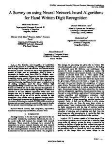
Figure 1: Typical neural network principal component analysis architecture.
of artificial intelligence in protective devices, the decisionmaking capability of the relays is enhanced. Early methods were based on desensitizing or delaying the relay to overcome the transients [2]. These methods are unsatisfactory nevertheless, since the transformer were exposed to long unprotected times. Improved security and dependability then was appreciated when the second harmonic content with respect to the fundamental one was introduced as an identification criterion, known as harmonic restraint differential protection [3]. However, some researchers reported the existence of a significant amount of the second harmonic in some winding faults [4, 5]. In addition, the new generations of power transformers use low-loss amorphous material in their core, which can produce inrush currents with lower harmonics contents and higher magnitudes [5]. In such cases, some authors have modified the ratio of second harmonic to fundamental restraining criterion by using other ratios defined at a higher frequency [6]. While other researchers proposed hidden Markov’s model [7], fuzzy-logic-based techniques [4, 8], wave shaped recognition technique [1, 9], and also artificial neural networks- (ANNs-) [10, 11] based learning pattern approach to get better classification accuracy, low computational burden, and fast response of the relay. However, these techniques depend on fixed threshold index (either in time domain or in frequency domain) and these may require large computational burden. Moreover, the performance of an ANN very much depends on its generalization capability, which in turn is dependent upon the data representation. One important characteristic of data representation is uncorrelated. In other words, a set of data presented to an ANN ought not to consist of correlated information. This is because correlated data reduce the distinctiveness of data representation and thus introduce confusion to the ANN model during learning process and hence, producing one that has low generalization capability to resolve unseen data. This suggests a need for eliminating correlation in the sample data before they are being presented to an ANN. This can be achieved by applying the principal Component Analysis (PCA) technique [12] onto input data sets prior to the ANN training as well as testing process and hence the neural network model becomes
neural network principal component Analysis (NNPCA) model. In this paper, a simple decision-making method based on the NNPCA is proposed for discriminating internal faults from inrush currents. The algorithm has been developed by considering different behaviors of the differential currents under internal fault and inrush condition. The NNPCA method extracts the relevant features from the differential current and reduces a training dataset to a lower dimension. The algorithm uses a data window of 12 samples per cycle. The algorithm also considers CT saturation and distinct scenarios such as changes in transformer load, source impedance, and remanent flux. All the mentioned conditions are simulated in PSCAD/EMTDC. The accuracy in classification, speed of response, and computational burden of the harmonic restraint method, NNPCA, feed-forward back-propagation neural network (FFBPNN), and symmetrical component based method are compared in the presented work.
2. Neural Network Principal Component Analysis Neural network principal component analysis (NNPCA) is basically an adaptive nonparametric method of extracting relevant information from confusing datasets [13]. It expresses data set in such a way as to highlight their similarities and differences. In 1982, Oja found a simple linear neuron model with a constrained Hebbian learning rule [13, 14]. For this work Hebbian learning is used. Generally, NNPCA is used for data reduction in statistical pattern recognition, signal processing, and image compression [13]. A typical architecture of NNPCA is shown in Figure 1. This network architecture has multilayer structure that is one input layer, one hidden layer, and one output layer. In backpropagation method a bounded and differentiable activation function is required. The sigmoid type activation function has all these properties making it popular in this training. In the present work due to these reasons, the hidden unit and output units use sigmoid-type of activation function. The architecture is defined by corresponding weights and connection scheme.
Advances in Artificial Intelligence
3
For a d-dimensional input data vectors z1 , z2 , . . . zd to m, output of neural network s1 , s2 , . . . , sm is given by (1) as si = Φ
315 MVA XT = 0.01 p.u. 10Ω
m �
wi zi ,
(1)
i=1
200 MVA
where
285 MW + 137.28 MVAR
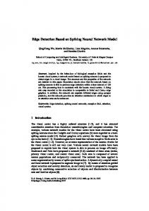
Figure 2: Typical three-phase power system. T
w = Connecting weight, wi = [wi1 , wi2 , . . . , wim ] , Φ = Nonlinear sigmoid activation function. The weight adapting (2) for neurons i is as following: ⎡
Δwi j = η⎣si zi − si
j �
⎤
wk j sk ⎦,
(2)
k=1
where η = learning rate, j = 1, 2, . . . , d and i = 1, 2, . . . , m.
3. Simulation and Training Cases Power transformer operating conditions may be classified as (i) normal condition, (ii) magnetizing inrush/sympathetic inrush condition, (iii) over-excitation condition, (iv) internal fault condition, (v) external fault condition. In the normal condition, rated or less current flows through the transformer. In this condition normalized differential current is almost zero (only no load component of current). Whenever there is large and sudden change in the input terminal voltage of transformer, either due to switching-in or due to recovery from external fault getting, a large current is drawn by the transformer from the supply. As a result, the core of transformer gets saturated. This phenomenon is known as magnetizing inrush, or in other words, inrush can be described by a condition of large differential current occurring when either the transformer is just switched on or the system recovers from an external fault. Similar condition occurs when transformer is energized in parallel with another transformer that is already in service; it is known as “sympathetic inrush” condition. Among the various faults in transformer, phase-to-ground fault occurs most frequently. On the basis of fault current, phase-toground fault, for protective device operation view point, may be further classified as (i) heavy faults, (ii) medium level fault and, (iii) low level fault. In all the cases, the abnormality nature is almost same but the magnitudes of currents resulting due to that are quite different. If the level of fault can be detected and accordingly
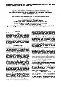
protective action is taken, then the major damage to the protected element can be prevented. A simulation software PSCAD/EMTDC is used to generate the training and testing signals under different operating conditions of transformer that are normal, overexcitation, magnetizing inrush, sympathetic inrush, and fault (phaseto-phase, phase-to-ground, and external fault) conditions. While simulating different operating conditions of transformer, energization angle, remanent flux in the core and load condition are considered as the magnitude and the wave-shape of differential current depends on these factors. Energization angle is varied from 0 to 360 degrees in interval of 30 degrees and remanent flux varying from 0% to 80% of the peak flux linkages generated at rated voltage with noload and full-load conditions to generate training signals while, in case of testing signals energization angle is varied in interval of 15 degrees. The desired remanence can be set in unenergized transformer with controlled DC current sources in PSCAD/EMTDC model [15]. As transformers are not expected to be subjected to more than 15% overvoltage hence, overexcitation condition is simulated by applying 115% of the rated voltage at full load. Three-phase transformers of 315 MVA at 400/220 kV, 200 MVA at 220/110 kV and 160 MVA at 132/220 kV, are modeled by using PSCAD/EMTDC. For the simulation of these transformers through PSCAD/EMTDC, the realistic data obtained from the M P State Electricity Board, Jabalpur India, is used. Typical connection of a 3-phase transformer of 315 MVA, 400/220 kV, 50 Hz, delta-star grounded connection is shown in Figure 2. In the high side, there is a source 200 MVA, 400 kV, and 10ω as internal impedance; in low side, there is a three-phase load of 285 MW and 137.28 MVAR. In case of internal fault condition, training and testing relaying signal is obtained by simulating fault varying from 1% to 99% of the power transformer winding turns, whereas in case of phase-to-ground fault condition, the fault is simulated at different location as 5%, 15%, 25%, 40%, 50%, and 100% (i.e., terminal fault) of the winding. Figure 3 shows a typical PSCAD/EMTDC transformer model required to simulate internal faults (turn to turn, phase to ground, and phase to phase) at different location of transformer winding from the neutral end of the windings. In this model MVA rating, voltage rating, base frequency, leakage reactance, magnetizing current, fault location (in %), and so forth can be defined. In [16] (3) is proposed to avoid saturation in CT and reduce the impact over the protective relays. However, in this work a reduced CT ratio as 600 : 5 and 1200 : 5 is selected to
Advances in Artificial Intelligence Operating signal (p.u.)
4
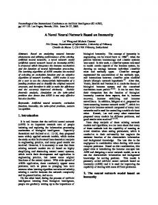
7 6 5 Switching-in occurred here 4 3 2 1 0 0.1 0.2 0.3 −1 0 Time (s)
0.4
0.5
Operating signal (p.u.)
Figure 4: Typical magnetizing inrush current waveform.
(a)
10 8 6 4 2 0 −2 −4 −6
Fault occurred here
0
0.1
0.2
0.3
0.4
0.5
Time (s)
Figure 5: Typical phase-to-ground fault current waveform.
4. Implementation of NNPCA-Based Algorithm, Results and Analysis
(b)
Figure 3: (a) Typical PSCAD/EMTDC transformer model to simulate internal fault (b) Typical PSCAD/EMTDC transformer model to simulate internal faults at different locations.
allow distortion in the waveform of the differential current as part of the stable state operation. Consider � � �X � � + 1� · IF · ZB ≤ 20, �R �
(3)
where IF , is maximum fault current per unit of CT rating, ZB is CT burden per unit of standard burden, and X/R is the reactance/resistance ratio of power system, respectively. The test signals (typical magnetizing inrush and internal fault conditions) obtained by simulation of transformer are shown in Figures 4 to 5. The simulation was done at the rate of 12 samples per cycle of 50 Hz AC supply in view of reported experience on different digital relay deigns [17]. The developed fault detection algorithm was implemented in MATLAB on Intel P-IV processor-based desktop with frontside bus (FSB) speed of 400 MHz.
The differential current is typically represented in discrete form as a set of 12 uniformly distributed samples obtained over a data window of one cycle of fundamental frequency signal, that is, the sampling rate is 12 samples per cycle. These 12 samples are called a “pattern.” The sliding data window, consisting, one most recent and other of previous windows is used to generate patterns under above-mentioned power transformer operating conditions. Each row of the input training matrix represents one pattern while corresponding row of target matrix represents desired output. Suppose that the inrush condition signal is characterized by the following sequence: i = [i1 , i2 , . . . , ik ].
(4)
The first row of inrush matrix takes 12 samples of i (i.e., i1 to i12 ), and then second row elements are from i2 to i13 and so on until all the elements of i are completed. In a similar fashion, the internal fault condition matrix elements are also arranged for training and testing. The complete training matrix contains both inrush and fault patterns. Two types of principal component analysis (PCA) data processors had been used for the purpose. The first one is called the preprocessor PCA, which is responsible for preprocessing input training data, to eliminate correlation in training patterns. The second is called postprocessor PCA, used to transform the validation and test datasets according to their principal components. The implementation was carried out with aid of built-in function supported by MATLAB Neural Network Toolbox. In proposed NNPCA architecture three-layered structure is used. The input layer has 12 neurons. The hidden layer
Advances in Artificial Intelligence
5
consists of 11 neurons, as the number of neurons in hidden layer increases, the error decreases but after certain number of neurons it increases again, and in this case the minimum error is obtained for 11 neurons in the hidden layer. Therefore, the number of neurons in the hidden layer is optimal for this application. As only single output (trip or not) is required, the output layer consists of just one neuron. After much experimentation on various neural network architectures, the presented model is proposed which has lesser neurons in all three layers. To differentiate between the fault and inrush conditions, the inrush condition is indicated by “0” and “1” indicates the fault condition. Out of 925 sets of data (patterns), 777 pattern sets are used to train the proposed NNPCA model. Out of these 777 pattern sets, 444 pattern sets are for the inrush (including sympathetic inrush patterns) and 333 are for the internal fault. The remaining 148 sets (which are not made part of training sets) are used to test the network’s generalization ability. These 148 test exemplar pattern sets contain internal fault and inrush condition only as these two conditions are very difficult to discriminate as compared to other operating conditions such as external fault, overexcitation, and normal condition. Out of 148 test patterns, 74 test sets were inrush patterns and remaining 74 test sets were internal fault patterns. The inrush test patterns consist of sympathetic inrush patterns and magnetizing inrush patterns at different switching-in angles, while internal fault test patterns are made up of phase-to-ground fault and phase-to-phase fault at different locations. After the NNPCA model had been trained, their generalization performances were calculated based on the mean absolute error (MAE) given by MAE =
P � |Ti − Si |,
(5)
i=1
where P is the total number of test patterns, Ti is the actual output, and Si is the NNPCA’s estimated output for the ith test pattern. Flow chart of the proposed algorithm (Figure 6) clearly indicates the steps for discriminating different operating conditions of power transformer. The external fault and normal operating condition are ruled out based on amplitude of two consecutive peaks of the operating signal. The overexcitation condition is determined by comparing voltage-tofrequency ratio with the rated voltage-to-frequency ratio. If this condition does not exist, then inrush and internal fault conditions are checked by NNPCA model. It gives tripping signal only if internal fault condition is detected. For different conditions of the test set, fault current magnitude, load condition, remanent flux, and switching angle are changed to investigate the effects of these factors on the performance of the proposed algorithm. Since the waveshape of inrush current changes with variation of switchingin instant of transformer, hence it is varied between 0 to 360 degrees. Similarly, due to the presence of the remanence flux, magnitude of inrush current may be as high as 2 to 6 times of inrush current without that, although the wave-shape remains same. It is found that the NNPCA
Start
Input data (operating signal)
Overexcitation/ normal operation?
Yes
No Check for inrush or fault by NNPCA/symmetrical component method?
Inrush
Fault Issue trip signal
Figure 6: Flow chart of presented algorithm.
classifier-based relay is stable even with such high magnitude of inrush current caused by remanence flux whereas, the conventional harmonic-based relay may maloperate due to such high magnitude of inrush current [4, 18]. A rigorous experimentation has been made to evaluate performance of the NNPCA model. The proposed NNPCA model is successfully tested using relaying signals obtained by modeling the transformer on PSCAD/EMTDC and simulating various operating conditions as mentioned in the previous section. The results of proposed algorithm are shown in Table 1 (Tables 1(a) and 1(b)). All the test patterns were accurately classified by the NNPCA model (i.e., 100% accuracy in classification). This detection is without any false positive or negative (as given in (6)); thus NNPCA has good generalization capability to distinguish between magnetizing inrush and internal fault condition of transformer. From Table 1, it is clear that the accuracy in classification of NNPCA is better than the FFBPNN based classifier in spite of using the same topology, same tuning parameter, and training algorithm as used in case of NNPCA method. We halve the following: Classification Error (in %) =
No. of False Positive + No. of False Negative × 100, Total Number of Test Cases
Classification Accuracy (in %) = 100 − Classification Error (in %).
(6) Table 2 presents the number of postdisturbance samples required for decision making by the proposed NNPCA-based transformer differential protection algorithm. In internal fault cases, it requires 6 samples (and 9 samples for light internal fault case) after the fault occurrence that means
6
Advances in Artificial Intelligence Table 1: (a) Performance of NNPCA and FFBPNN having topology of 12-11-1
Neural network topology NNPCA FFBPNN
Training error
Max. epoch
0.0001 0.0001
1000 1000
Inrush P −1.0 −1.0
Fault A 0.0 0.0
P 0.96 0.96
A 1.0 1.0
P: predicted, A: actual. (b) Accuracy in classification (%)
Trained transformer ratings 315 MVA 200 MVA 160 MVA
315 MVA FFBPNN 99.32 94.59 94.59
NNPCA 100 100 100
Tested transformer ratings 200 MVA FFBPNN NNPCA 94.59 100 99.32 100 96.32 100
160 MVA FFBPNN NNPCA 98.64 100 98.64 100 100 100
Table 2: Number of postdisturbance samples required for decision by NNPCA-based relay. Cases Magnetizing inrush (0◦ ) Internal fault (5% to 98%) Internal fault (light phase-to-ground fault at 2%)
Number of samples required (actual) 8 6 9
about 10–15 ms are required for the fault detection while in case of inrush condition only 8 samples are required, that is, 13.33 ms. However, it is observed that the relay operation is independent from the harmonic present in the operating signal, and therefore no filtering is required in this method. In addition to that it does not require any threshold index to discriminate between the inrush and internal fault condition of transformer. The same power transformers are tested with symmetrical component method and harmonic restraint (HR) method based on discrete fourier transform (DFT) (see the section Appendix). Park’s vector I p is a function of positive-, negative-sequence currents and independent of zero-sequence currents. When plotting vectors in Park’s space, α is represented in the horizontal axis, while β component is plotted in the vertical axis. The secondary winding currents are not affected by the fault or inrush if the vector I p is plotted in Park’s space. Internal faults and inrush currents may be characterized by particular plot shape of I p . When Park’s vector is plotted in Park’s space, transformer internal fault and inrush currents are clearly distinguished from their plot shape as shown in Figures 7 and 8. From Figures 7 and 8, it is observed that the plots are symmetrical for internal fault condition and asymmetrical for inrush condition. The shape characterizations in two groups are not dependent on the type of differential signal (fault or inrush). The use of Park’s vectors reduces appreciably the computation requirements, since their values are directly calculated from a scalar matrix product.
Maximum samples required (Logical) 12 12 12
Discrete fourier-transform- (DFT-) based harmonic restraint method is implemented, to compare performance of the proposed optimal NNPCA-based algorithm in power transformer differential protection. Figure 9 shows the ratio of second harmonic to fundamental of the differential current under typical magnetizing inrush and internal fault conditions, respectively. During one cycle under internal fault condition, the ratio of the second harmonic is quite high and in the same range as in case of magnetizing inrush condition. Therefore, it is difficult to discriminate between internal fault and inrush conditions merely setting a preset threshold. From Figure 9, it is also clear that the ratio values are fluctuating, which create problem to decide a preset threshold. Moreover, due to the presence of second harmonic during internal fault condition, digital relay will take longer time to make trip decision (one cycle or more than one cycle). In contrast, the optimal NNPCA based method is able to detect such a fault in 6 ms (half cycle or with in half cycle) and in light internal fault cases, it requires 9 samples after the fault occurrence that means about 15 ms are required for the fault detection while in case of inrush condition only 8 samples are required, that is, 13.33 ms. However, it is observed that the relay operation is independent from the harmonic present in the operating signal, and therefore no filtering is required in this method. However, the harmonic restraint method and symmetrical component method are capable to discriminate between these two conditions but do not seem to be intelligent to take decision in case of fluctuating ratio of second harmonic to fundamental of the differential current due to different
Advances in Artificial Intelligence
120
90
4 3
150
7
60 30
180
0
210
330
0
330 240
270
(a)
0
210
300
240
30
180
330
210
2
150
30
180
300
60
60
150
270
4
120
2
2 1
240
90
90 4
120
(b)
300 270 (c)
Figure 7: Plot for an inrush ((a), primary winding currents, (b) centre secondary winding currents, (c) differential current).
120
90
15
60
120
90
120
180
0
330
210
180
0
210 300
60 30
5
0
210
330 240
300 270
270
(a)
15
180
330 240
300
150
30
270
90
10
150
30
5
240
60
2
10 150
4
(b)
(c)
Figure 8: Plot for internal fault condition ((a), primary winding currents, (b) centre secondary winding currents, (c) differential current).
can take decision. Moreover, these methods take more time to take decision as compared to NNPCA-based transformer differential method and depend on the harmonic contain present in the relaying signal.
Ratio of second to fundamental component
1.8 1.6 1.4 1.2 1
5. Conclusion
0.8 0.6 0.4 0.2 0 0
0.05
0.1 0.15 Time (s)
0.2
0.25
Inrush case Internal fault case
Figure 9: Ratio of second harmonic to fundamental of the differential current under typical inrush and internal fault condition.
loading conditions, severity of internal faults, switching-in angles, and so forth, and hence maloperation of relay will occur. In case of symmetrical component method, Park’s space plot is to be analyzed for its symmetry than only relay
This paper presents a novel intelligent approach based on neural network principal component analysis (NNPCA) model to solve the problem of distinguishing between transformer internal fault and magnetizing inrush condition. The performance of NNPCA-based method is compared with feed-forward back-propagation neural network (FFBPNN), harmonic restraint method, and Park’s plot method. The proposed NNPCA algorithm is based on waveform identification technique which is more accurate than traditional harmonic-restraint-based technique, especially in case of modern power transformers which use high-permeability low-coercion core materials. The conventional harmonic restraint technique may fail because high second harmonic components may be generated during internal faults and low second harmonic components during magnetizing inrush with such core materials. However, the harmonic restraint method and symmetrical component method are capable to discriminate between
8
Advances in Artificial Intelligence
these two conditions but do not seem to be intelligent to take decision in case of fluctuating ratio of second harmonic to fundamental of the differential current. Moreover, these methods take more time to take decision as compared to NNPCA-based transformer differential method. The proposed optimised NNPCA technique is simple in architecture, fast in operation, and robust. The present neural network model issues tripping signal in the event of internal fault within 6–15 ms of fault occurrence. The method is also immune from the DC offset in relaying signals due to saturation of CT core in the event of internal or external fault. Moreover, the NNPCA-based algorithm has 100% accuracy in classification which is not possible to achieve by using FFBPNN in the application of power transformer differential application.
differential current is analyzed in terms of its Fourier series, and amplitude of each harmonic can be found as follows:
Appendix
B. Symmetrical Component Approach [6]
A. Discrete Fourier Transform (DFT) Algorithm
A function of instantaneous line currents (ir1 , i y1 , ib1 ), the current Park’s vector components are obtained as follows:
Fn2 = a2n + bn2 ,
where Fn = Fourier coefficients and n = 1, 2, 3, . . . , N. For power transformers protection, F1 , F2 , and F5 represent the Fourier coefficients of the fundamental, the second harmonic, and the fifth harmonic component, respectively, of current waveform. For a three-phase transformer, the combined harmonic components of the differential currents are 2 2 2 2 = a2na + bna + a2nb + bnb + a2nc + bnc , FnCombined
⎡
2 T
(A.1)
2 an = T bn =
2 T
0
(A.2)
f (t) cos(nωt)dt,
where a0 is the dc component (average value) and an and bn are the sine and cosine components of the Fourier coefficients, respectively. If the waveform is sampled at time ti , space δt apart, so that there are N = T/δt samples, then for samples 1 to N, the coefficients an and bn in (A.2) can be rewritten as
2� 2πni an = X(ti ) sin , N i=0 N n
2� 2πni bn = X(ti ) cos , N i=0 N n
(B.1)
ib1
(A.3)
where X(ti ) are the discrete sampled current signals and i = 1, 2, 3, . . . , N. Hence, for 12 samples per data window, 12 Fourier coefficients will have an array size of 12 × 1. Both sine and cosine terms will have an array size of 12 × 12. The
⎤
⎡
(B.2)
⎤
iα2 ir2 ⎢ ⎥ ⎢ ⎥ ⎣iβ2 ⎦ = [c]⎣i y2 ⎦. i02 ib2
�T 0
⎤
1 1 ⎤ − ⎥ √2 ⎥ √2 ⎢ 3 3⎥ 2⎢ ⎢0 ⎥ − ⎥, [c] = ⎢ 2 3 ⎢ ⎥ 3⎢ ⎥ ⎣1 1 1 ⎦ 2 2 2 ⎡
f (t) sin(nωt)dt,
ir1
⎢1 −
f (t)dt,
�T
⎡
⎡
�T 0
⎤
i01
with coefficients a0 =
iα1
⎢ ⎥ ⎢ ⎥ ⎣iβ1 ⎦ = [c]⎣i y1 ⎦,
where the transformation matrix [c] is defined as
∞
a0 � + (an sin(nωt) + bn cos(nωt)), 2 n=1
(A.5)
where n = 1, 2, and 5.
Any continuous waveform f (t), having a finite energy in the interval (0.T), can be represented in the interval as a Fourier series: f (t) =
(A.4)
(B.3)
Park’s vector I p is defined as the vector difference between Park’s vectors obtained by means of (B.1) and (B.3) is used. And it is analytically demonstrated that the park’s vector I p is related to the time-dependent symmetrical components as follows:
(n)
(n)
�
I p = nΣ I1(n) e j(φr1 +nωt) + I2(n) e− j(φr2 +nωt) ,
(B.4)
where I1 is the instantaneous rms value (i.e., since the rms of the current I1 changes over the time during transients and this values is considered to be recalculated for every instant) of the positive sequence current for the differential current, I2 is the instantaneous rms value of the negative sequence current for the differential current, φr1 is the phase angle of the positive sequence current in line r, φr2 is the phase angle of the negative sequence current in line r, t the time, ω is the supply fundamental frequency, n is the order of the considered harmonic, and superscript (n) refers to the nth order harmonic value. Park’s vectors are obtained from the instantaneous line currents by means of the [C] matrix of (B.2). Thus,
Advances in Artificial Intelligence
9
the transformation of nth-order harmonic time-dependent symmetrical components into Park’s vector components is achieved as follows: ⎡
⎤ ⎡ (h) ⎤ (h) (h) √ I1 e j(φr1 +hωt) + I2(h) e− j(φr2 +hωt) i(h) α ⎢ (h) ⎥ ⎢ ⎥ ⎢i ⎥ = [c][s]−1 2 × ⎢I (h) e j(φr2(h) +hωt) + I (h) e− j(φr1(h) +hωt) ⎥. 2 1 ⎣β ⎦ ⎣ ⎦ � 2 (h) (h)
I0(h) e j(φ0
i(h) 0
+hωt)
+ e− j(φ0
+hωt)
(B.5) The plot in Park’s plane of the α and β components accounting for all the harmonics is then �� n
�
(n) i(n) = α + jiβ
�
(n)
(n)
�
I1(n) e j(φr1 +nωt) + I2(n) e− j(φr2 +nωt) .
n
(B.6) In Park’s space, α is represented in the horizontal axis, while β component is plotted in the vertical axis.
References [1] M. Tripathy, R. P. Maheshwari, and H. K. Verma, “Advances in transformer protection: a review,” Electric Power Components and Systems, vol. 33, no. 11, pp. 1203–1209, 2005. ´ [2] P. Arboleya, G. D´ıaz, J. Gomez-Aleixandre, and C. Gonz´alezMor´an, “A solution to the dilemma inrush/fault in transformer differential relaying using MRA and wavelets,” Electric Power Components and Systems, vol. 34, no. 3, pp. 285–301, 2006. [3] H. K. Verma and G. C. Kakoti, “Algorithm for harmonic restraint differential relaying based on the discrete Hartley transform,” Electric Power Systems Research, vol. 18, no. 2, pp. 125–129, 1990. [4] M. C. Shin, C. W. Park, and J. H. Kim, “Fuzzy logicbased relaying for large power transformer protection,” IEEE Transactions on Power Delivery, vol. 18, no. 3, pp. 718–724, 2003. [5] S. A. Saleh and M. A. Rahman, “Modeling and protection of a three-phase power transformer using wavelet packet transform,” IEEE Transactions on Power Delivery, vol. 20, no. 2, pp. 1273–1282, 2005. [6] S. Ala, M. Tripathy, and A. K. Singh, “Identification of internal faults in power transformer using symmetrical components and Park’s plots,” in Proceedings of IEEE International Conference on Power Systems, IIT, Kharagpur, India, December 2009. [7] X. Ma and J. Shi, “New method for discrimination between fault and magnetizing inrush current using HMM,” Electric Power Systems Research, vol. 56, no. 1, pp. 43–49, 2000. [8] D. Barbosa, U. C. Netto, D. V. Coury, and M. Oleskovicz, “Power transformer differential protection based on Clarke’s transform and fuzzy systems,” IEEE Transactions on Power Delivery, vol. 26, no. 2, pp. 1212–1220, 2011. [9] J. Ma, Z. Wang, Q. Yang, and Y. Liu, “Identifying transformer inrush current based on normalized grille curve,” IEEE Transactions on Power Delivery, vol. 26, no. 2, pp. 588–595, 2011. [10] L. G. Perez, A. J. Flechsig, J. L. Meador, and Z. Obradovic, “Training an artificial neural network to discriminate between magnetizing inrush and internal faults,” IEEE Transactions on Power Delivery, vol. 9, no. 1, pp. 434–441, 1994. [11] P. Bastard, M. Meunier, and H. Regal, “Neural networkbased algorithm for power transformer differential relays,” IEE Proceedings, vol. 142, no. 4, pp. 386–392, 1995.
[12] J. E. Jackson, A User’s Guide to Principal components, Wiley, Hoboken, NJ, USA, 2003. [13] S. Haykin, Neural Network: A Comprehensive Foundation, Pearson Education, New Delhi, India, 2008. [14] C. M. Bishop, Neural Networks for Pattern Recognition, Oxford University Press, New York, NY, USA, 1995. [15] D. Woodford, Introduction To PSCAD V3, Manitoba HVDC Research Centre, Manitoba, Canada, 2001. [16] S. E. Zocholl, Analyzing and Applying Current Transformers, Schweitzer Engineering Laboratories, Pullman, Wash, USA, 2004. [17] M. S. Sachdev, “Microprocessor relays and protection systems,” IEEE Tutorial Course Text 88EH0269-1-PWR, 1988. [18] M. R. Zaman and M. A. Rahman, “Experimental testing of the artificial neural network based protection of power transformers,” IEEE Transactions on Power Delivery, vol. 13, no. 2, pp. 510–515, 1998.
Journal of
Advances in
Industrial Engineering
Multimedia
Hindawi Publishing Corporation http://www.hindawi.com
The Scientific World Journal Volume 2014
Hindawi Publishing Corporation http://www.hindawi.com
Volume 2014
Applied Computational Intelligence and Soft Computing
International Journal of
Distributed Sensor Networks Hindawi Publishing Corporation http://www.hindawi.com
Volume 2014
Hindawi Publishing Corporation http://www.hindawi.com
Volume 2014
Hindawi Publishing Corporation http://www.hindawi.com
Volume 2014
Advances in
Fuzzy Systems Modelling & Simulation in Engineering Hindawi Publishing Corporation http://www.hindawi.com
Hindawi Publishing Corporation http://www.hindawi.com
Volume 2014
Volume 2014
Submit your manuscripts at http://www.hindawi.com
Journal of
Computer Networks and Communications
Advances in
Artificial Intelligence Hindawi Publishing Corporation http://www.hindawi.com
Hindawi Publishing Corporation http://www.hindawi.com
Volume 2014
International Journal of
Biomedical Imaging
Volume 2014
Advances in
Artificial Neural Systems
International Journal of
Computer Engineering
Computer Games Technology
Hindawi Publishing Corporation http://www.hindawi.com
Hindawi Publishing Corporation http://www.hindawi.com
Advances in
Volume 2014
Advances in
Software Engineering Volume 2014
Hindawi Publishing Corporation http://www.hindawi.com
Volume 2014
Hindawi Publishing Corporation http://www.hindawi.com
Volume 2014
Hindawi Publishing Corporation http://www.hindawi.com
Volume 2014
International Journal of
Reconfigurable Computing
Robotics Hindawi Publishing Corporation http://www.hindawi.com
Computational Intelligence and Neuroscience
Advances in
Human-Computer Interaction
Journal of
Volume 2014
Hindawi Publishing Corporation http://www.hindawi.com
Volume 2014
Hindawi Publishing Corporation http://www.hindawi.com
Journal of
Electrical and Computer Engineering Volume 2014
Hindawi Publishing Corporation http://www.hindawi.com
Volume 2014
Hindawi Publishing Corporation http://www.hindawi.com
Volume 2014