Int'l Journal of Computing, Communications & Instrumentation Engg. (IJCCIE) Vol. 2, Issue 2 (2015) ISSN 2349-1469 EISSN 2349-1477
Practical Implementation of a Concurrent Trimming Approach for Manganin Shunt Resistors Siti Nabilah Misti, Martin Birkett, David Bell, Roger Penlington
The normal approach in trimming the shunt resistors requires a trial and error approach (i.e. measure the resistance value, calculate how much material to remove, trim the shunt resistor based on the amount of material to be removed and finally measure the resistance after the shunt has been trimmed). As the normal approach of testing and modifying the test subject is a step by step process, it can take an excessively long time to complete. Therefore by adopting the concurrent engineering method, in the product development and for a large scale manufacture the production time can be significantly reduced. Concurrent engineering, also known as simultaneous engineering is a method of designing and developing products, in which the different stages run simultaneously, rather than consecutively. Recent relevant research studies [8-11] have discovered that the concurrent method decreases product development time and also the time to market, leading to improved productivity and reduced costs. Though initial implementation can be challenging, the competitive advantage means it is beneficial in the long term. It removes the need to have multiple design reworks, by creating an environment for designing a product right the first time round. Similarly, with the trimming approach for the shunt, there are a number of stages that needed to be considered in order to reduce the tolerance of the resistor. The concurrent trimming approach is different from the normal process because it anticipates the amount of material that needs to be removed from the shunt resistors in its testing stages. The main purpose of concurrent trimming is to simultaneously trim and measure the resistive material without the need to retest the trimmed part afterwards. Whereby applying the concurrent technique, the result will be obtained faster and the design of the newly trimmed shunt resistor can be finalized. However, the concurrent trimming approach needs to be done carefully because if there is a mistake in removing the resistive material, the process might have to be repeated with a new shunt resistor. Therefore, precision in this stage is crucial. The concurrent approach can be used in two different ways which are by automated and manual approach. The automated system will need a much large amount of investment than the manual process. Thus, the manual approach will be a more suitable process to test the theory and determine if the concurrent trimming approach is worthwhile.
Abstract— As electrical energy prices continue to rise each year, accurate energy consumption monitoring becomes increasingly important. Therefore, there is a growing demand for high precision, low value shunt resistors in order to measure the flow of electrical current in applications such as smart energy meters and electric vehicle charging stations. This paper will discusses the concurrent trimming approach using machining to reduce the standard ±5% tolerance of 100µΩ Manganin shunt resistors which is used in metering applications. The experimental results reveal that the concurrent trimming approach can reduce the standard trimming time by more than 50% more than half the normal trimming time. The resistance value of shunt is obtained approximately at 100µΩ and is in the range of targeted value of 100µΩ with tolerance of less than ±5%.
Keywords—Concurrent trimming, Manganin shunt resistor, machining, tolerance. I. INTRODUCTION Manganin shunt resistors are used in smart energy meters to determine the amount of energy consumed by the household. These shunt resistors are typically manufactured by using a Manganin alloy element that is electron beam welded to two copper terminations. Due to the current manufacturing techniques used in the production of the Manganin shunt, it is difficult to produce resistors to an accurate dimensions and hence precise resistive tolerances. Currently, this configuration can achieve resistance values down to 100µΩ with tolerances of ±5% [1-3]. Consequently, manufacturers of the shunt resistors are still looking at ways to reduce the tolerance, hence improving the accuracy and precision of the device. Precise resistance of the shunt can be calibrated through a process known as trimming, where material is partially removed or "trimmed" from the shunt until the resistance reaches its targeted value [4, 5]. This, only works if the shunt resistors are intentionally manufactured with a lower resistance than the targeted value. Theoretically, by trimming the resistive material into a tolerable and symmetrical shape, it can lower the standard tolerance of the shunt resistors [6, 7]. By removing controlled amounts of Manganin from the shunt, the tolerance of the Manganin shunt resistors can be lowered to less than ±5%. Siti Nabilah Misti*, Martin Birkett, David Bell and Roger Penlington, are with Northumbria University Newcastle, United Kingdom *Emailid:
[email protected]
http://dx.doi.org/10.15242/IJCCIE.D0814003
81
Int'l Journal of Computing, Communications & Instrumentation Engg. (IJCCIE) Vol. 2, Issue 2 (2015) ISSN 2349-1469 EISSN 2349-1477
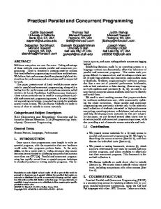
Fig. 1: Block diagram of the experimental setup.
also clamped in a nylon jig to insulate it from the machine vice. The shunt was connected to two electrically conductive cables to deliver the current and another cable to measure the voltage values. The current cable was fixed to the shunt and jig by using 6mm diameter nut and bolt while the voltage sense cable was directly soldered to two pre-welded tin plated termination pins on the shunt using silver solder. For the Agilent B2902A Power Source, the current was set to be an output of 1A with the voltage limit set to 0.5V. Table II shows that the combined measurement accuracy for the Agilent 34420A 7.5 Digit Nano-Volt/Micro-Ohm Meter with the Agilent B2900A Power Source gives a total system error of 0.186%. This must be taken into account when analyzing results from this work.
II. THE EXPERIMENT SETUP Fig. 1 depicts the block diagram of the experimental setup for the proposed research, with the relevant parameters summarized in Table I. The concurrent trimming approach encompasses three main building blocks, which include: Bridgeport milling machine, Agilent B2902A Power Source and Agilent 34420A 7.5 Digit Nano-Volt/Micro-Ohm Meter. TABLE I PARAMETERS OF THE EXPERIMENTAL SETUP Agilent B2900A Power Source Parameter
Value
Data Source Modulation format
Amps (I)
Source rate
TABLE II MEASUREMENT SYSTEMS ACCURACY
1A
Source ranging
1 µA
Limit
0.5 V
Force
± 250 V max
Value Parameter
Agilent B2900A Power Source
% Reading
0.03
Offset
0.0015
Pulse Peak
0 nA
Delay
5 ms 50 µs
Agilent 34420A NanoVolt/Micro-Ohm Meter
0.0002
% Range
Trigger (Auto) Source
1
Total error
0.0018
0.000000012
Measure
1
Total % Error
0.18
0.006
Value
Total System % Error
Agilent 34420A Nano-Volt/Micro-Ohm Meter Parameter Function Range/Digits
DCV/ Temp
The concurrent trimming approach for this experiment involved an operative to carry out every action needed in the normal process. However, instead of measuring resistance and then trimming small amounts of Manganin from the shunt resistor consecutively, it is possible to continuously measure the resistance value using the combination of Agilent B2902A Power Source and Agilent 34420A 7.5 Digit NanoVolt/Micro-Ohm Meter, whilst simultaneously removing the Manganin from the shunt resistor. By carrying out the
7
Max Measurement level
12 V
Sense
Ω 4W
For the Bridgeport milling machine, a 3mm diameter endmill cutting tool was chosen for the experiment as the milling area will be on Manganin strip which has a width of 5mm. The shank of the cutting tool was electrically insulated from the milling machine using a nylon sleeve. The shunt resistor was http://dx.doi.org/10.15242/IJCCIE.D0814003
0.186
82
Int'l Journal of Computing, Communications & Instrumentation Engg. (IJCCIE) Vol. 2, Issue 2 (2015) ISSN 2349-1469 EISSN 2349-1477
measuring and milling actions simultaneously or concurrently, it will be quicker than doing the actions separately or consecutively as with the normal trimming process.
Estimation of the change in resistance at the higher machining speed can be made by using 0. 028µΩ/µm (i.e., the value calculated from Table III). This estimation will help in achieving the main objective which is to lower the tolerance of ±5% for the Manganin shunt resistor. After the initial resistance readings are recorded, the value will be deducted from the target value of the shunt resistor (i.e., resistance value of 100µΩ) and then divided by 0.028µΩ/µm to predict the depth of cut for the milling process for any Manganin shunt resistor.
III. METHODOLOGY AND POST-ANALYSIS A. Data Acquisition Upon feeding 1A of current to the Manganin shunt resistors from the Agilent B2900A Power Source the initial values of resistance were taken before the trimming process started. Resistance values were taken every 15 seconds for 1 minute, to allow the voltage readings from the nano-volt meter to stabilize. Following this, the end mill cutter position was zeroed against the surface of the Manganin area to be trimmed. Then, the value of depth of cut was set using a dial test indicator (DTI), before the milling procedure took place. For initial testing, the Manganin was cut dry at two different cutting speeds of 500m/min and 1000m/min and the feed rate was kept constant at 50m/min. During cutting process, the nano-volt meter digital readout displayed the voltage slowly increasing until it reached the target value of 100µΩ. The milling action was then stopped and the trimmed shunt resistor was removed from the jig.
IV. RESULTS AND DISCUSSIONS Result generated from MATLAB in Fig. 2 show that the resistance change can be predicted before the milling process by using the change of resistance acquired and calculated in the trial runs. Comparing the calculated value and the actual result, the prediction or estimation is proven to be reliable. These findings suggest that the concurrent trimming approach is a feasible method to monitor the rate of change for the resistance of Manganin shunt resistor and to determine the desirable depth and amount of material removal from Manganin strip. The depth of the end mill cutter must be concurrently examined with the micro-ohm meter readings to identify if the trimming process needs to be stopped before the depth of cut reaches the calculated amount.
B. Computation of Material Removal Resistance values recorded from the initial testing in Table III and Table IV were compared and it can be clearly seen that the faster speed of the spindle; the more accurate values are recorded. TABLE III INITIAL TRIALS BY USING FAST SPINDLE SPEED Sample Number
Average Initial Resistance (µΩ)
Depth of cut (mm)
Average Resistance After (µΩ)
1
101.795
0.04
102.597
2
102.463
0.04
103.574
3
103.451
0.04
104.675
TABLE IV INITIAL TRIALS BY USING SLOW SPINDLE SPEED Sample Number
Average Initial Resistance (µΩ)
Depth of cut (mm)
Average Resistance After (µΩ)
1
104.473
0.04
106.502
2
106.115
0.04
108.524
3
108.139
0.04
110.574
Fig. 2: The corresponding resistance values of the Manganin shunt resistors using different depth of cut to predict the rate of change for the resistance.
Over 20 initial trials were carried out and on average; the faster speed gives smaller rate of change which is 25.25µΩ/mm while slower speed gives higher rate of change of resistance which is 25.54µΩ/mm. This can be related to an increase in the amount of heat being transferred into the shunt at the slower machining speed. Based on the initial trials, the speed and the depth of the cut were used as a reference to predict the amount of material to be removed from the Manganin shunt resistors. The mean change of resistance of 1.1µΩ over 40µm depth gives an estimated rate of change of 0.028µΩ/µm.
http://dx.doi.org/10.15242/IJCCIE.D0814003
The calculated depth of cut can be used in order to find the amount of material to be removed and also to predict how much the resistance value will increase in accordance to the trials of concurrent trimming approach. Furthermore, Fig. 3 shows results for initial resistance and after the trimming process for concurrent trimming approach; where the required target is to achieve a resistance of 100µΩ. Only 3 samples are used for the experiment due to the limited number of sample received for this project. Sample 3 gives the highest value of resistances after the concurrent trimming approach is conducted which is 100.335µΩ whereas for Samples 1 and 2 are 100.081µΩ and 100.094µΩ respectively. 83
Int'l Journal of Computing, Communications & Instrumentation Engg. (IJCCIE) Vol. 2, Issue 2 (2015) ISSN 2349-1469 EISSN 2349-1477
The average value for all 3 samples is 100.17µΩ which is 0.17% of the tolerance resistance.
Manufacturing Technology, IEEE Transactions on, vol. 14, pp. 613-617, 1991. http://dx.doi.org/10.1109/33.83952 [6] F. Y. Wu, "Theory of resistor networks: the two-point resistance," J. Phys. A: Math. Gen., vol. 37, pp. 6653-6673, 2004. http://dx.doi.org/10.1088/0305-4470/37/26/004 [7] L. M. Landsberger. (2007, 22 November 2013). Simplifying Circuit Calibration With Electrically-Adjustable Resistors. [Microbridge Technical White Paper]. 10. Available: http://www.mbridgetech.com/pdfs/microbridge_032307.pdf [8] Y.-S. Ma, G. Chen, and G. Thimm, "Paradigm shift: unified and associative feature-based concurrent and collaborative engineering," Journal of Intelligent Manufacturing, vol. 19, pp. 625-641, 2008. http://dx.doi.org/10.1007/s10845-008-0128-y [9] E. A. Fielding, J. R. McCardle, B. Eynard, N. Hartman, and A. Fraser, "Product lifecycle management in design and engineering education: International perspectives," Concurrent Engineering, vol. 22, pp. 123134, 2014. http://dx.doi.org/10.1177/1063293X13520316 [10] D. Yang and M. Dong, "A hybrid approach for modeling and solving product configuration problems," Concurrent Engineering, vol. 20, pp. 31-42, 2012. http://dx.doi.org/10.1177/1063293X11436219 [11] H.-C. Chang and H.-Y. Chen, "Optimizing product form attractiveness using Taguchi method and TOPSIS algorithm: A case study involving a passenger car," Concurrent Engineering, p. 1063293X13520317, 2014.S. P. Bingulac, “On the compatibility of adaptive controllers (Published Conference Proceedings style),” in Proc. 4th Annu. Allerton Conf. Circuits and Systems Theory, New York, 1994, pp. 8–16. http://dx.doi.org/10.1177/1063293X13520317
Fig. 3: Graph of resistance vs. depth of cut for the concurrent trimming of Manganin shunt resistors.
V. CONCLUSION Results from this paper have shown that the concurrent trimming process is a viable method of trimming the resistance value of Manganin shunt resistors It offers improved trimming accuracy and reductions in time and process costs when compared to the normal consecutive process. This procedure has the potential for application in large scale manufacture when the best point of reference of the trimming process for the shunt resistors is discovered and it will give a lot of benefit to the manufacturer in terms of quality assurance, time and cost. By using concurrent trimming in this experiment, the tolerance of the Manganin shunt resistors is reduced from ±5% of tolerance to less than ±0.5% in a shorter time compared to the normal consecutive trimming process.
About Author (s): Siti Nabilah Misti is currently a PhD researcher at the Department of Mechanical Engineering, Northumbria University Newcastle, United Kingdom. She received her MSc degree in Engineering from the Northumbria University in 2012 and BSc degree in Production & Operation (Manufacturing) from Universiti Tun Hussein Onn Malaysia (UTHM), Malaysia in 2008. She worked as Operation Manager for 3 years back in Malaysia before furthered her studies for master degree. Her research interests include product and process development and optimization, Total Productive Management (TPM) and manufacturing. Martin Birkett is a Senior Lecturer within the Mechanical Engineering Department at Northumbria University, UK. He worked in the manufacturing industry for sixteen years and also did some part time lecturing. During the time in the industry, he completed a Craft Apprenticeship in Engineering Maintenance before moving on to work as a Production Engineer and then Senior Research and Development Engineer. During this period, he also continued to study on a part-time basis for ONC/HNC and then my BEng (Hons) and PhD degrees, both of which are completed at Northumbria University. His research interests include development and optimization of materials and manufacturing processes.
ACKNOWLEDGMENT This work is funded and supported by Majlis Amanah Rakyat, Malaysia (MARA).
REFERENCES [1]
[2] [3]
[4]
[5]
TT Electronics. (2009, Resistors For Energy Metering - Application Note. (2). Available: http://www.ttelectronics.com/z_downloads/tt_ electronics_metering_brochure.pdf Vishay Intertechnology, "Application Note: Resistive Products," ed, 2008. Isabellenhütte Company. (2012, Low-Ohmic Precision And Power Resistors. 14. Available: http://www.isabellenhuette.de/uploads/media/ IHH_Bauelementebroschuere_engl_01.pdf P. Mach and P. Svasta, "Influence of trimming of resistive thick films on nonlinearity of their current vs. voltage characteristics," in Electronics Technology: Meeting the Challenges of Electronics Technology Progress, 2004. 27th International Spring Seminar on, 2004, pp. 309-312 vol.2. T. Tobita and H. Takasago, "New trimming technology of a thick film resistor by the pulse voltage method," Components, Hybrids, and
http://dx.doi.org/10.15242/IJCCIE.D0814003
David Bell was awarded a BSc in Industrial Technology from Newcastle upon Tyne Polytechnic in 1985 and an MSc in Industrial Technology from Teesside Polytechnic in 1986. He is a Fellow of the Higher Education Academy and prior to that a Member of the ILT since 2002. He is currently employed as Associate Dean International within the Faculty of Engineering and Environment at Northumbria University. He has worked at Northumbria University in various roles since 1982 including the role of Acting Dean for 16 months. Prior to academia he worked in industry for companies such as Thorn, Electrolux and
84
Int'l Journal of Computing, Communications & Instrumentation Engg. (IJCCIE) Vol. 2, Issue 2 (2015) ISSN 2349-1469 EISSN 2349-1477 Moores International as a Manufacturing Engineer, Engineering Manager and Business Manager. Current research interests include Manufacturing improvement tools. He became a member of the IET and Chartered Engineer in 1986. Roger penlington is Research Fellow in the Department of Mechanical and Construction, Northumbria University, UK. He did his first degree at Sheffield City Polytechnic and his PhD was in glass manufacture at Sheffield Hallam University (SHU). He joined Northumbria in 1994 to undertake research into glass manufacture specifically aspects related to heat transfer, fluid flow and forming processes. He took up a lecturing role in 1998 and have been awarded a Teaching Fellowship in recognition of research into engineering education. His research interests are in the areas of manufacturing technology with particular reference to fluid dynamics and heat transfer in glass manufacture and electronic components. He also active in engineering education research serving on the steering committee of the UK Engineering Education Education Special Interest Group. In his research, he seek to retain links between industry and academia through project sponsorship and also currently serve as President of the Society of Glass Technology.
http://dx.doi.org/10.15242/IJCCIE.D0814003
85