Gressin, A., Mallet, C., Demantké, J., David, N., 2013. Towards. 3D lidar point cloud registration improvement using optimal neighborhood knowledge. ISPRS ...
The International Archives of the Photogrammetry, Remote Sensing and Spatial Information Sciences, Volume XL-4/W5, 2015 Indoor-Outdoor Seamless Modelling, Mapping and Navigation, 21–22 May 2015, Tokyo, Japan
Practical implementation of semi-automated as-built BIM creation for complex indoor environments Sanghyun Yoona, Jaehoon Junga, Joon Heoa
a
School of Civil and Environmental Engineering, Yonsei University, 134 Shinchon-dong, Seodaemun-gu, Seoul 120-749, Republic of Korea Commission/WG
KEY WORDS: As-built BIM, Laser scanner, Point clouds, RANSAC
ABSTRACT: In recent days, for efficient management and operation of existing buildings, the importance of as-built BIM is emphasized in AEC/FM domain. However, fully automated as-built BIM creation is a tough issue since newly-constructed buildings are becoming more complex. To manage this problem, our research group has developed a semi-automated approach, focusing on productive 3D as-built BIM creation for complex indoor environments. In order to test its feasibility for a variety of complex indoor environments, we applied the developed approach to model the ‘Charlotte stairs’ in Lotte World Mall, Korea. The approach includes 4 main phases: data acquisition, data pre-processing, geometric drawing, and as-built BIM creation. In the data acquisition phase, due to its complex structure, we moved the scanner location several times to obtain the entire point clouds of the test site. After which, data pre-processing phase entailing point-cloud registration, noise removal, and coordinate transformation was followed. The 3D geometric drawing was created using the RANSAC-based plane detection and boundary tracing methods. Finally, in order to create a semantically-rich BIM, the geometric drawing was imported into the commercial BIM software. The final as-built BIM confirmed that the feasibility of the proposed approach in the complex indoor environment. process is divided into four main steps: (1) data acquisition; (2) data pre-processing; (3) data processing; (4) BIM creation.
1. INTRODUCTION Digital representation of physical and functional characteristics of a facility, known as Building Information Models (BIMs), is now widely used in the Architecture, Construction, Engineering, and Facility Management (AEC/FM) domain due to its potential strength of supporting the planning stage and modelling of building life cycle (Gu and London, 2010; Hichri et al., 2013). Along with the proliferation of BIM, there is an increasing demand of constructing a BIM for actually built or currently existing buildings. Having an accurate as-built model of the existing structure can significantly improve the facility management process (Woo et al., 2010). For as-built BIM creation, laser scanners play a crucial role: they can rapidly and accurately reconstruct the 3D scene of the surrounding environments represented by so-called ‘point cloud’ data (Canciani et al., 2013). However, the process of asbuilt BIM creation is labor-intensive and error-prone operations since it is largely a manual process (Anil et al., 2011). Automatic extraction of as-built BIM from point clouds has been studied by many researchers, but fully-automated method has not yet been developed due to complex indoor structure (Huber et al., 2011; Jung et al., 2014; Valero et al., 2012a; Valero et al., 2012b; Xiong et al., 2013). Alternatively, our research group has focused on improving the performance and productivity of the as-built BIM creation by semi-automatic approach (Jung et al., 2014). In this paper, we aimed to verify the feasibility of the developed approach by implementing it to the complex indoor environment, Charlotte stairs in Lotte World Mall, Korea. The following sections explain detailed steps of methodology in consecutive order. General overview of the process is depicted in Fig.1. The
Figure 1. General overview of the process
2. PRACTICAL IMPLEMENTATION 2.1 Data acquisition The test site, Avenuel Atrium includes a huge void space, from basement level to 8th floor, and two complex spiral structures, Charlotte stairs (Fig. 2). The stairs are connecting the 1st and 2nd floors, crossing each other. For the modelling of Charlotte stairs, we collected the point-cloud data from basement level to 2nd floor of the void space. Due to the occlusions by clutter such as fences, columns, and decorations, we needed to move the scanner locations several times. In this study, FARO Focus 3D, which is compact and simple to use for indoor laser
This contribution has been peer-reviewed. doi:10.5194/isprsarchives-XL-4-W5-143-2015
143
The International Archives of the Photogrammetry, Remote Sensing and Spatial Information Sciences, Volume XL-4/W5, 2015 Indoor-Outdoor Seamless Modelling, Mapping and Navigation, 21–22 May 2015, Tokyo, Japan
scanning, was utilized. To scan the entire Charlotte stairs, the total number of 11 scanning was conducted in different locations: five times for the 1st floor; four times for the 2nd floor where the stairs are connected; twice for the basement. Fig. 3 shows the example of locations on the floor plan (1st floor) where the data was acquired in.
each scan data, such as a corner or distinguishable spot of the environment was identified. After that, using target-less registration function, we could merge 11 scanned point-cloud data into a common coordinate system. 2.2.2 Noise removal: During the scanning process, noisy data caused by moving objects, decorations and laser reflections diffused onto glass surface could be included in the point clouds. Therefore, the noise removal is prerequisite to provide the proper input for as-built BIM creation. In this study, the registered point-cloud data was imported to Leica Cyclone 8.0, and the noisy data was manually removed. 2.2.3 Coordinate transformation: The filtered point-cloud data needs to be transformed to the World Coordinate System (WCS) for the purpose of its future application with GIS or display on the map. We surveyed 18 control points in the test site using a total station. The surveying was based on the welldistributed and clearly identifiable points such as corners of walls and stairs. After which, Helmert 3D transformation was conducted to transform the coordinate system from local to world. 2.3 Generation of 3D geometric drawings
Figure 2. Charlotte stairs
The registered and filtered point clouds still includes a huge number of point data, which later lead to slow-down or system failure during the modelling process. To facilitate the use of point-cloud data in creating as-built BIM, such simplification or reduction of point data is prerequisite. This goal can be achieved by generation of 3D geometric drawing, proposed in our preceding studies (Heo et al., 2013; Jung et al., 2014). Geometric drawing is composed of three sub-procedures: (1) segmentation; (2) refinement; and (3) boundary tracing. The following sections briefly explain each process . 2.3.1 Segmentation: The segmentation process is based on RANSAC algorithm (Okorn et al., 2010) which can extract inliers from a set of observations containing abundant outliers. Throughout RANSAC algorithm point-cloud data which have the identical plane model parameter are divide to each plane.
Figure 3. Scan position in 1st floor and picture of position number 11, 13 2.2 Data pre-processing 3D point clouds acquired from the previous step are required to go through a pre-processing phase before being used for the generation of geometric drawing. In this phase, the sets of scanned points are combined into a single point cloud in a common coordinate system. Also, the point cloud needs to be filtered for the removal of unwanted data (Tang et al., 2010). 2.2.1 Registration: The point clouds acquired from different locations are respectively represented by local coordinate system. Therefore, each local coordinate system should be unified as a common coordinate system through a process known as registration (Tang et al., 2010). Since the test site suffers from many occlusions and specialized target positioning because of the void space, the manual registration was conducted instead of fully automated methods (Gressin et al., 2013; Huber and Hebert, 2003; Makadia et al., 2006; Xie et al., 2010). For registration commercial software, Autodesk Recap Pro which provides target-less registration, was used. The scanned point-cloud data was imported to the software and the locations of the particular points that are clearly recognizable in
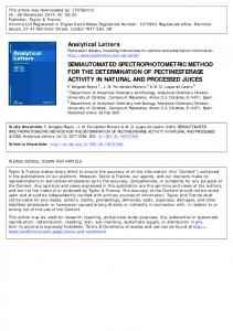
2.3.2 Refinement: This process begins with defining the size of Refinement Grid Cell (RGC) as the cell size of binary image. After the size of RGC is defined, the points which are included in the segmented plane are projected onto a 2D binary image. From this binary image the labelling process is performed to extract the plane of interest and remove the others that are considered to be noise. 2.3.3 Boundary tracing: Boundary tracing process requires a parameter which is called Tracing Grid Cell (TGC). From the binary image that only includes the plane of interest, the boundary pixels are searched respectively and sequentially. For the hollow parts such as windows and open doors, the inverse binary image is created to search the boundary pixels with the same procedure. Finally, traced boundaries are inversely returned to their original coordinates. 2.3.4 3D geometric drawing: Fig. 4-a shows the Charlotte stairs in the test site, and Fig. 4-b shows the created 3D geometric drawing of the structure. The boundaries that traced out from the segmented planes, are shown as white lines and un-segmented points by the RANSAC segmentation are represented as red points. Using both the traced lines and the remaining points, the structure can be intuitively accessible. In
This contribution has been peer-reviewed. doi:10.5194/isprsarchives-XL-4-W5-143-2015
144
The International Archives of the Photogrammetry, Remote Sensing and Spatial Information Sciences, Volume XL-4/W5, 2015 Indoor-Outdoor Seamless Modelling, Mapping and Navigation, 21–22 May 2015, Tokyo, Japan
addition, the data sizes of the original point clouds were significantly reduced from 881 MB to 8 MB. This reduction allows to efficiently manipulate the 3D model in the BIM software without slow-down or system failure.
investigated in ongoing work. In addition, prior to BIM creation, noise removal for scanning data was performed manually by the modeler, which is very time-consuming and tedious work. This process therefore will require automation or some other techniques of improving productivity.
Figure 4. Detail components of 3D geometric drawings 2.4 As-built BIM creation Typically, as-built BIM creation involves three aspects: (1) modelling geometry of the components; (2) assigning an object category and material properties to a component; and (3) establishing relationships between components (Tang et al., 2010). However, in this work, the material properties of each structures were assumed since geometric modelling is the main focus of the present work. The geometric drawing and the remaining points of the test site was exported as CAD-oriented DXF format and used as an input for a commercial BIM software Autodesk Revit 2014. As-built BIM production in Revit can be broadly divided into three steps: 1) grid and level creation; 2) walls and floor creation; and 3) detail modelling. For the grid-level creation step, the height levels of the structure should be defined. For the test site, 6 height levels were defined according to the specific structures such as the floors, ceilings, and stairs. The building boundaries were created according to the geometric drawing, and the gridlines were then traced. Fig. 5-a shows the defined height levels and gridline developed in the modelling. Following the grid and level creation, the walls and floor creation proceeded as shown in Fig. 5-b. Subsequently, as shown in Fig. 5-c, the modelling of the details, such as stairs and fences were conducted. The final result of the as-built BIM is depicted in Fig. 6.
Figure 5. As-built BIM creation steps
3. CONCLUSIONS In this study, the developed semi-automated as-built BIM approach has shown to be useful in creating as-built BIM model for complex indoor environment. In order to obtain the entire point-cloud data from a highly cluttered and occluded test area, we moved the laser scanner 11 times, and merged them using the target-less registration method. In addition, by using the total station measurements, we transformed the point-cloud data set into the world coordinate system for its future application with GIS or display on the map. The proposed approach also provided a geometric drawing, including detail-rich components while reducing the data size, which allows efficient modelling in BIM software. However, the current RANSAC-based segmentation process showed some limitations in segmenting highly non-linear structures such as curved fences and circular columns. Given the growing trend of irregularly-shaped buildings, techniques for segmentation of such non-linear structures should be
Figure 6. Completed model of as-built BIM
This contribution has been peer-reviewed. doi:10.5194/isprsarchives-XL-4-W5-143-2015
145
The International Archives of the Photogrammetry, Remote Sensing and Spatial Information Sciences, Volume XL-4/W5, 2015 Indoor-Outdoor Seamless Modelling, Mapping and Navigation, 21–22 May 2015, Tokyo, Japan
REFERENCE
Acknowledgements
References from Journals: Anil, E.B., Tang, P., Akinci, B., Huber, D., 2011. Assessment of the quality of as-is building information models generated from point clouds using deviation analysis, IS&T/SPIE Electronic Imaging. International Society for Optics and Photonics, pp. 78640F-78640F-78613. Canciani, M., Falcolini, C., Saccone, M., Spadafora, G., 2013. From point clouds to architectural models: algorithms for shape reconstruction. International Archives of the Photogrammetry, Remote Sensing and Spatial Information Sciences 40, 25-26. Gressin, A., Mallet, C., Demantké, J., David, N., 2013. Towards 3D lidar point cloud registration improvement using optimal neighborhood knowledge. ISPRS Journal of Photogrammetry and Remote Sensing 79, 240-251. Gu, N., London, K., 2010. Understanding and facilitating BIM adoption in the AEC industry. Automation in construction 19, 988-999. Heo, J., Jeong, S., Park, H.-K., Jung, J., Han, S., Hong, S., Sohn, H.-G., 2013. Productive high-complexity 3D city modeling with point clouds collected from terrestrial LiDAR. Computers, Environment and Urban Systems 41, 26-38. Hichri, N., Stefani, C., De Luca, L., Veron, P., 2013. Review of the «as-built BIM» approaches. Int. Arch. Photogramm. Remote Sens. Spat. Inf. Sci. 40, 107-112. Huber, D., Akinci, B., Oliver, A.A., Anil, E., Okorn, B.E., Xiong, X., 2011. Methods for automatically modeling and representing as-built building information models, Proceedings of the NSF CMMI Research Innovation Conference. Huber, D.F., Hebert, M., 2003. Fully automatic registration of multiple 3D data sets. Image and Vision Computing 21, 637650. Jung, J., Hong, S., Jeong, S., Kim, S., Cho, H., Hong, S., Heo, J., 2014. Productive modeling for development of as-built BIM of existing indoor structures. Automation in Construction 42, 68-77. Makadia, A., Patterson, A., Daniilidis, K., 2006. Fully automatic registration of 3D point clouds, Computer Vision and Pattern Recognition, 2006 IEEE Computer Society Conference on. IEEE, pp. 1297-1304. Okorn, B., Xiong, X., Akinci, B., Huber, D., 2010. Toward automated modeling of floor plans, Proceedings of the Symposium on 3D Data Processing, Visualization and Transmission. Tang, P., Huber, D., Akinci, B., Lipman, R., Lytle, A., 2010. Automatic reconstruction of as-built building information models from laser-scanned point clouds: A review of related techniques. Automation in construction 19, 829-843. Valero, E., Adán, A., Cerrada, C., 2012a. Automatic method for building indoor boundary models from dense point clouds collected by laser scanners. Sensors 12, 16099-16115. Valero, E., Adan, A., Cerrada, C., 2012b. Automatic construction of 3D basic-semantic models of inhabited interiors using laser scanners and RFID sensors. Sensors 12, 5705-5724. Woo, J., Wilsmann, J., Kang, D., 2010. Use of as-built building information modeling, Construction Research Congress, pp. 538-547. Xie, Z., Xu, S., Li, X., 2010. A high-accuracy method for fine registration of overlapping point clouds. Image and Vision Computing 28, 563-570. Xiong, X., Adan, A., Akinci, B., Huber, D., 2013. Automatic creation of semantically rich 3D building models from laser scanner data. Automation in Construction 31, 325-337.
This research was supported by a grant (11 High-tech G11) from the Architecture & Urban Development Research Program funded by the Korean Ministry of Land, Infrastructure and Transport.
This contribution has been peer-reviewed. doi:10.5194/isprsarchives-XL-4-W5-143-2015
146