EE JU
Journal of Urban and Environmental Engineering, v.1, n.1 (2007) 36–43
Journal of Urban and Environmental Engineering
ISSN 1982-3932 doi: 10.4090/juee.2007.v1n1.036043
www.journal-uee.org
PRACTICAL IMPLICATIONS OF USING INDUCED TRANSIENTS FOR LEAK DETECTION Marko V. Ivetic1∗ and Dragan A. Savic² 1
The Leverhulme Trust Fellow, Department of Engineering, School of Engineering and Computer Science, University of Exeter
2
Professor, Department of Engineering, School of Engineering and Computer Science, University of Exeter Received 5 December 2006; received in revised form 16 April 2007; accepted 18 March 2007
Abstract:
This paper deals with practical problems of leak detection by methods based on hydraulic transient analysis. Controlled and safe transients can be generated and the response of the network, with the relevant information, can be monitored and analysed. Information about leaks, contained in the monitored pressure signal, cannot be easily retrieved, due to reflections, noise etc. On the basis of numerical experiments on a simple network, merits and limitations of several methods for signal analysis (time domain analysis, spectral density function and wavelet transform) have been examined. Certain amount of information can be extracted from the time history of the pressure signal, assuming the first reflection of the pressure wave is captured with very high time resolution and accuracy. Only relatively large leaks can be detected using this methodology. As a way to increase the sensitivity of this method it is suggested that transforms in frequency domain and, especially, wavelet transforms, are used. The most promising method for leakage location and quantification seems to be based on wavelet analysis.
Keywords:
pipe networks, leak detection, hydraulic transients © 2007 Journal of Urban and Environmental Engineering (JUEE). All rights reserved.
∗
Correspondence to: Marko V. Ivetic, Tel.: +44 1392 263730. E-mail:
[email protected]
Ivetic and Savic
37
INTRODUCTION In many water supply systems a significant amount of water is lost on the way from the treatment plant to consumers. Typically it is in the range of 20 to 30 %, but very often it can be as high as 50 % of the production. The situation in developing countries and countries in transition is more serious. Due to the significant increase of construction costs for expanding system capacity and the energy for pumping, water treatment and distribution, water companies are forced to reduce water losses. In spite of obvious economic benefits, the lack of highly trained personnel and high expense of tracing and repairing leaks, can make water companies reluctant to use leakage detection on a wider scale. In addition to the methods used so far (Eiswirth & Burn, 2001), which are used with limited efficiency, there is a need for an effective, non-intrusive method which will provide information on the state of the network and to be used in leak detection. The idea is to perform controlled and safe experiments on the network by closing/opening of some valves, and to monitor the response of the network. Due to reflections of the incident pressure wave, the measured pressure/flow signal contains information on the network layout, and on the leaks. The part of the signal that represents the response of the “healthy” system can be used in calibration of the network and to assess the influence of leaks. The latter is masked by random noise and measurement errors, unknown demand, minor reflections from irregularities in the network, and attenuated and transformed by friction (steady state and unsteady as well). Abstraction of useful information for leakage detection is the main task in this analysis. Many water distribution systems are monitored to a certain extent, but the real use of these measurements in leak detection is rarely a part of regular or maintenance practice. If some of these measurements are carefully planned and slightly modified they can provide useful information in leakage detection. The potential of transient hydraulic analysis for providing better understanding of a water network behaviour has been known (Wylie & Streeter, 1978; Ligget & Chen, 1995), and several significant contributions to the analysis of this problem have been recently published (Vitkovsky & Simpson, 1997; Brunone et al., 2001; Mpesha et al., 2002). Practical significance of results presented so far is limited since conditions in real life networks significantly differ from those analysed theoretically or in the laboratory conditions. Several intermediate steps are necessary, and the intention of this paper is to help fill that gap.
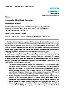
Fig. 1 Diffraction of a pressure wave caused by a leak.
1. In a frictionless pipeline pressure wave could be generated by an instantaneous valve manoeuvre at the downstream boundary. Change of flow (∆Q) is associated with the change of pressure head (∆H) propagating at the wave celerity (a) in the upstream direction. The relationship between the flow change and the associated pressure change is known as the Joukowsky relation:
∆H = −
∆Q a AP g
(1)
where (AP) is pipe cross-sectional area, and (g) acceleration due to gravity. When the initial pressure wave reaches the section where the water is leaking, a part of the wave, equal to δH, is reflected, and the rest of the wave front reduced by that amount, will continue to travel. The change of the pressure head (δH) is proportional to the change of leakage flow (∆q). If (∆H) is positive, leakage will increase, and the effective flow change caused by the valve manoeuvre will be reduced. With the assumption that the leak area and the discharge coefficient, (CL, AL), remain unchanged if the pressure head increases, and by using Eq. 1, one can obtain the estimate of the reflected wave:
δH =−
⎞a ∆qL a q0 ⎛ ∆H * = − 1⎟ ⎜ 1+ ⎟g AP g AP ⎜⎝ H0 ⎠
(2)
where q0 is the steady state leak flow at pressure head equal to H0.
q0 = CL AL 2 gH 0
(3)
Hydraulics/Time domain analysis Theoretical basis for using inverse transients in leakage detection is based on considerations presented in Fig. 1.
It should be noted that the modified initial pressure wave (∆H*= ∆H - δH), is included in Eq. 2. In the great
Journal of Urban and Environmental Engineering (JUEE), v.1, n.1, p.36-43, 2007
Ivetic and Savic
majority of cases the term (CLAL), a flow characteristic of a leak, has a very small value. The experimental data (Brunone & Ferrante, 2001) provide useful information for leaks of the order of a few percent of the pipe area, while the leaks in real life systems are smaller. From Eq. 2 it is obvious that the reflected wave is inversely proportional to the pipe area (diameter to the power two), or directly proportional to the relative velocity change (∆q/AP). The relative velocity change is proportional to the initial surge overpressure, scaled by the steady state pressure head at the position of a leak, to the power of 0.5. In real water distribution systems the same principle can be applied although the phenomenon is much more complex. The Joukowsky relation (1) is not sufficient and the complete partial differential equations, dynamic and continuity, have to be used (Wylie and Streeter, 1978). Simulation models based on the Method of Characteristics (MOC) are commonly used to solve these equations. According to recent experiments, modelling of friction term has to be modified to account properly for the influence of unsteady velocity profile (Vardy & Hwang, 1991). In the experiments in laboratory conditions (Brunone & Ferrante, 2001), overpressure caused by sudden valve closure is several times bigger than the initial pressure. In the majority of practical cases this is not acceptable. The reflected part of the pressure wave represents the signature of the leak, and has to be detected by measurements and properly interpreted. For the success of any methodology for leak detection based on transient analysis it is important to obtain δH as distinct and large as possible. On the other hand, the safe operation of the network requires the initial pressure wave (∆H) is kept within the safe limits.
Practical limitations of using induced transients are directly related to the trade-off existing between the minimum pressure change caused by a leak (that needs to be distinguished from the noise in the measured signal), and the maximum overpressure (that can be safely induced in the system). If the considerations start from the value of δH that can be detected, it is possible to obtain an estimate of the minimum detectable leak. Although this is closely related to the local conditions, available equipment, etc., it can be illustrated with an example with the layout and notation from Fig. 1. Let us assume that there is a leak on a simple pipeline, located at the distance L1, from the boundary where a transient is induced. The pipe diameter is equal to 300 mm, wave velocity a = 1000 m/s, and the steady state pressure head at the location of the leak H0 = 30 m (100 ft). If the overpressure of 20 m can be induced, there will be an increase in the leak by 29 %, causing a reflection of the wave, which will be measured at the monitoring point. The minimum detectable change of
38
pressure head is around 0.3 – 0.6 m (1 – 2 ft), that corresponds to leaks between 0.7 and 1.4 l/s. If the initial pressure wave is sharp then the location of the leak can be determined from the time when the reflected pressure wave arrives. Obviously, for larger pipe diameters, or smaller induced overpressures, the minimum detectible leak by the time domain analysis could be quite large, i.e. impracticable. Power spectral density The analysis in frequency domain helps to identify natural frequencies of the system and provides means of filtering out noise. New frequencies introduced by leaks can be easier to identify and the sensitivity of the method can be increased. There are several attempts to use spectral density functions to determine the location of a leak. Brunone & Ferrante (2001) pointed out that apart from the obvious benefit in using this technique, there are some shortcomings and problems with identification of new frequencies introduced by leaks. Mpesha et al. (2002) used a forced vibration technique (oscillating valve) in the numerical simulation to identify natural frequencies in the system. They claim high sensitivity of the method and the possibility to determine very low level leaks, both location and the size. The problem associated with practical applications of this technique is the increased danger of having very high-pressure oscillations at natural frequencies of the system. Many accidents in hydropower systems happened due to the standing wave oscillations. Wavelet transform In water distribution systems the energy in transients changes with time. The information on the rate of energy change, caused by leakage, but also by demand and friction, cannot be obtained from the power spectral density function. Wavelet transforms provide information on energy contained in transients in frequency domain (actually scales, which are directly related to the period of oscillation) and how it changes with time. The possibility (and potential) to use the wavelet transforms is clearly indicated by Ferrante et al. (2001). There is an extensive list of references on wavelets (Torrence & Compo, 1998), and on more traditional methods (Covas et al., 2005), like Fast Fourier Transforms (FFT). Before attempting to use these transformations one has to be aware of all the limitations of the numerical procedures used (like required sampling resolution, number of data points, etc.) and the means of improving the significance of obtained transforms (the influence of added zeros, averaging in time and scale directions etc.). Wavelet transforms and transforms of the signal into frequency domain are obtained in this paper using the software made available by Torrence & Compo (1998).
Journal of Urban and Environmental Engineering (JUEE), v.1, n.1, p.36-43, 2007
Ivetic and Savic
Wavelet transforms are presented like surfaces with frequency axis on the log scale. In vertical direction they are not scaled so it is possible to make comparisons between individual diagrams. Spectral density functions are presented on the log - log diagrams. They are not scaled to obtain unit area below the diagram for the same reason of comparison between different cases. Results of Analysis A set of numerical experiments (Ivetic, 1996) on a relatively simple test network (Fig. 2) have been done to gain the information on transients necessary for planing field experiments. The numerical experiments aim to illustrate the character of transients in water distribution systems. The network consists of pipes of the same diameter, 200 mm, with two reservoirs, R-1 and R-2,
39
one loop, several hydrants and two valves. The first valve (V-1) is almost completely opened, while the second valve (V-2) is used as a pressure sustaining valve. Their actual role in this example is to introduce some additional disturbances to the signal. Pressure is “monitored” at M-1, M-2, M-3 and M-4, leaks are at L1 and L-2, and the hydrant, used for generation of transients, is at H. Initially, flow from R-1 to R-2 is around 20 l/s, equally distributed over two branches of the loop. Transients are generated by closing or opening the hydrant with the maximum capacity of around 1 l/s. Time step used for calculation was dt = 0.01 s. Circles in Figs. 2 and 3, represent calculation nodes positioned at the distance travelled by a pressure disturbance during one time step. The fence diagram in Fig. 3, represents instantaneous elevations of the hydraulic grade line. Transients are generated by fast closing of the hydrant at (H) and positions of wave fronts are indicated. How to induce transients?
Fig. 2 Network layout: R-1 and R-2 upstream and downstream reservoir, H - hydrant used for induced transients, L-1 and L-2 positions of hypothetical leaks, M-1 to M-4 positions where hypothetical pressure histories are simulated.
Fig. 3 Simulation snapshot: pressure wave caused by closing hydrant valve at position (H).
This is the most important question. Sudden closure of any of the two valves (V-1), or (V-2), in a test network will cause large pressure oscillations and even column separation. As hydrant tests are already used for steady state measurements it is logical to select one hydrant and equip it with a fast closing valve. Hydrant opening is usually a safer operation than hydrant closing, but anyway, both manoeuvres are something that network has to be able to withstand. Simulation results for the fast opening and closing of a hydrant valve are given as pressures at all monitoring positions in Fig. 4 (as a time series), and at M-1 in Figs. 5 (as a spectral density function) and 6 (as wavelet transforms). Significantly faster attenuation of pressure oscillations caused by valve opening can be noticed (Fig. 4). However, the frequency content of power spectral density functions (Fig. 5) is very similar. Peaks at frequencies 0.8 - 0.9 Hz and 2.5 Hz, are more pronounced in the case of valve closing. The first peaks in both diagrams are introduced by the finite length of the analyzed signal (equal to 9 s). Wavelet transforms provide more information than spectral density functions. A part of the diagram which is more important for this analysis is closer to the viewer, i.e. smaller scales or shorter periods (as indicated by the lower log wave number). Note also that the resolution of the wavelet transform is not uniform in time and in period (scales) directions. For smaller scales (high frequencies) better resolution is achieved in time direction, and for large scales (low frequencies) better resolution is achieved in the frequency direction. It can be noticed that once opened the hydrant continues to have a role in pressure wave reflections, which results in the introduction of a new scale (small ridges indicated by the arrow in Fig. 6b).
Journal of Urban and Environmental Engineering (JUEE), v.1, n.1, p.36-43, 2007
Ivetic and Savic
40
Fig. 4 Time series of pressure heads caused by sudden hydrant closure and opening.
(a) (b) Fig. 5 Power spectrum estimates for (a) hydrant closing and (b) hydrant opening, of pressure at M-1.
(a) (b) Fig. 6 Wavelet transforms (WT) of pressure oscillations caused by (a) closing and (b) opening of hydrant valve. Journal of Urban and Environmental Engineering (JUEE), v.1, n.1, p.36-43, 2007
Ivetic and Savic
Due to the practical difficulty of distinguishing between the contributions of the two outflows from the system, i.e. leakage and the hydrant flow, it is advised that the preferred manoeuvre should be valve closing. Preferable methodology The analysis of pressure signal in time domain (similar to Brunone & Ferrante, 2001) is illustrated in Fig. 7, where the pressure signals at the same location (without and with leak) are plotted. In the case with a leak the pressure signal is copied and shifted up for easier identification of the reflection (δH). Although there is a certain difference between the two signals caused by a leak, it is not so easy to determine the position and the size of the leak, unless the first reflection is accurately captured. The first third of the signal is enlarged, with the initial and reflected pressure waves, (∆H) and (δH), as indicated in Fig. 7b. In the rest of the signal there is a change in the period of oscillation and a new smaller
41
scale of oscillation is introduced, but nothing more can be deduced from the diagram. If the signal is transformed into frequency domain, it is easy to distinguish the new frequency, although it is by two orders of magnitude smaller than the dominant frequency of oscillation. The most useful is the signal transformed into wavelet form (Fig. 8). Resolution in terms of frequencies in the region of higher frequencies is generally low for both the power spectral density function and wavelets. It is, however, difficult to determine exactly the new frequency introduced by a leak. It can be seen from the wavelet transform that there is a regular pattern, small ridges elongated in the direction of frequency. They are associated with large amplitude oscillations but they last very short time. Their time pattern can be easily recovered from the wavelet transform, easier than from the time series. In the power spectral density function their significance is downsized by averaging, and no time pattern can be recovered.
(a) (b) Fig. 7 The analysis of pressure signal at M-1, in time domain: (a) longer monitoring (9.00 s); (b) enlarged signal (3.00 s).
Fig. 8 Power spectrum estimate (PSD) and wavelet transform (WT) for a fast valve (0.05 s) hydrant closing with leak at L-1, pressure at M-1 Journal of Urban and Environmental Engineering (JUEE), v.1, n.1, p.36-43, 2007
Ivetic and Savic
42
Fig. 9 Power spectrum estimate (PSD) and wavelet transform (WT) for a slow (0.5 s) hydrant closing with leak at L-1, pressure at M-1.
Fig. 10 Wavelet transforms of pressure oscillations at M-1 (left) and at M-4 (right) caused by closing hydrant, with the leak at L-1.
Sudden or slow valve closure Several numerical experiments were done with relatively slow valve closure (0.5 s, still fast, but one order of magnitude slower). From the transformed signal in Fig. 9, it can be seen that the frequency content is very poor and hardly anything can be recovered on the characteristics of the leak. Position of the monitoring point The best position for measurement is close to the location where the transient is induced. By moving
away from the hydrant more disturbances are being superimposed, resulting in the masking of the disturbance which is sought, e.g. induced by the leak. Wavelet transforms of pressures at locations M-1 and M-4 are given in Fig. 10. RECOMMENDATIONS Relatively small progress in the practical applications of transient analysis for leak detection has been made so far. The significance of a pressure signal is changing rapidly in time, by both, interacting (and aliasing) with other reflections and weakening due to friction and
Journal of Urban and Environmental Engineering (JUEE), v.1, n.1, p.36-43, 2007
Ivetic and Savic
escape of water from the system. Therefore, induced transients can be used only as a local technique, i.e. near the locality which is indicated as the one with possible leaks. In distribution networks it is better to plan measurements during the night time due to lower demand, which otherwise my have large influence on attenuation of oscillations (similar to leakage). The valve manoeuvre (closing is better than opening) has to be fast, if transient analysis is to be used for leakage detection. The induced overpressure has to be safe, but significant enough to ensure detectable reflections from leaks. The field experiment for leak detection has to be carefully planned. With the known characteristics of the network and of the valve used for generating transients, one can easily check target values for the accuracy and resolution of measurements. Certain amount of information can be extracted from the time series of the pressure signal, only if the first reflection of the pressure wave is captured with very high time resolution and accuracy. Only relatively large leaks (more appropriate name is “bursts”) can be detected. As a way to increase sensitivity of the method one can use transforms into frequency domain and especially, wavelet transforms. Two aspects of the change of the pressure signal caused by the presence of a leak, additional frequency and the increased rate of attenuation can be correctly identified only in the wavelet space. As the additional frequency is higher than the basic frequencies, appropriate time resolution of pressure signal sampling is required. Although there are indications that wavelet transforms can be used for locating and quantifying leaks by recovering the time pattern in the region of high frequencies and a measure of signal attenuation, there is currently no known methodology to do so. Further work is directed toward the development of such a methodology. ACKNOWLEDGEMENT: The research presented in this paper has been prepared during the stay of the first author at The University of Exeter as the Leverhulme
43
Trust Fellow. This work was also supported by the Advanced Research Fellowship AF/000964 awarded to the second author by the U.K. Engineering and Physical Sciences Research Council. The financial help of the Leverhulme Trust and the EPSRC is greatly appreciated. REFERENCES Brunone B. & Ferrante M. (2001) Detecting leaks in pressurised pipes by means of transients. J. of Hydraulic Research, 39(5), 539-547. Covas D., Ramos H. & Almeida B. (2005) Standing wave difference method for leak detectionin pipeline systems J. of Hydraulic Engineering, 131(12), 1106-1116. Eiswirth, M., & Burn, L.S. (2001) New methods for defect diagnosis of water pipelines. Proc. 4th Int. Conf. on Water Pipeline Systems Managing Pipeline Assets in an Evolving Market, York, UK, BHR Group Ltd., 137-150. Ferrante, M., Brunone, B. & Rossetti, A.G. (2001) Leak detection in pressurised pipes by means of wavelet analysis. Proc. 4th Int. Conf. on Water Pipeline Systems Managing Pipeline Assets in an Evolving Market, York, UK, BHR Group Limited, 259-275. Ivetic, M.V. (1996) HYTRA – Hydraulic Transient Analysis manual. Faculty of Civil Engineering, Belgrade. Karney B.W. (1990) Energy relations in transient closed-conduit flow J. of Hydraulic Engineering, 116(10), 1180-1196. Ligget, J.A., & Chen, L.C. (1995) Monitoring water distribution systems: the inverse method as a tool for calibration & leak detection. Cabrera, E. & Vela, A.F. (eds.) Improving efficiency & reliability in water distribution systems. Kluwer Academic Publishers, 107-132. Mpesha, W., Choudhry, M.H., & Gassman, S.L. (2002) Leak detection in pipes by frequency response method using a step excitation J. of Hydraulic Research, 40(1), 55-62. Stefanovic, N., & Ivetic M.V. (1998) Procedure for leak detection in simple pipelines (in Serbian). Proc. 12th Congress of IAHR, Subotica. Torrence, C., & Compo, G. P. (1998) A practical guide to wavelet analysis. Bull. Am. Met. Soc., 79(1), 61-78. Vardy, A.E., & Hwang, K.L. (1991) A characteristic model of transient friction in pipes. J. of Hydraulic Research, 29(5), 669683. Vitkovsky, J.P., & Simpson, A.R. (1997) Calibration & leak detection in pipe networks using inverse transient analysis & genetic algorithms. Res. Rep. No. R157, Univ. of Adelaide, Australia. Wylie, E.B. & Streeter V.L. (1978) Fluid Transients, McGraw-Hill.
Journal of Urban and Environmental Engineering (JUEE), v.1, n.1, p.36-43, 2007