Proceedings of the 13th WSEAS International Conference on SYSTEMS
Prediction of Limit Cycles in nonlinear systems with ideal relay type nonlinearities by using Multiple-input Describing Functions VALERI MLADENOV Department of Theoretical Electrical Engineering, Technical University of Sofia 8, Kliment Ohridski St, Sofia-1000, Bulgaria; e-mail:
[email protected] also with MSM group, Dept. Electrical Engineering, Eindhoven University of Technology P.O. Box 513, 5600 MB Eindhoven, the Netherlands Abstract: - In this paper we present some results and simulations about the limit cycle prediction in nonlinear systems with relay type nonlinearities using Multiple-input describing functions. The introduction of Describing Functions (DFs) theory is given, together with the derivations of three-sinusoid-input describing functions for the ideal relay nonlinearity. Then the application of this approach for analysis of the limit cycles in second order nonlinear systems with ideal relay type nonlinearity is shown. The applicability of the approach is demonstrated by example. Key-Words: - Nonlinear systems, Multiple-input describing functions, Three-sinusoid-input describing functions, Limit cycles, Ideal relay written as a function dependent on e = a sin(ωt ) . This becomes f (e) = f (a sin(ωt )) for zero reference input. From the Fourier series expansion of the output signal of the nonlinear block we get the following equation:
1 Introduction The describing function method (or short DF method) is an approximate procedure for investigating the existence of limit cycles in the feedback system shown in Figure 1. The concept is one of quasilinearization where a static nonlinear characteristic is represented by a gain depending upon the magnitude of the input signal. The input signal is evaluated on the assumption that it is a sinusoid. In this light the input signal of the nonlinear block NL will be in the following form: e = a sin(ωt ) . x
+
e
v NL
L(s)
∞
f (a sin ωt ) = ∑ [ ak (a ) sin ωt + bk (a) cos ωt ] ≈ k =0
≈ a1 (a) sin ωt + b1 (a ) cos ωt = = a1 (a ) 2 + b1 (a ) 2 sin(ωt + ϕ (a )) =
= N (a ) sin(ωt + ϕ (a )) a1(a) and b1(a) are the fundamental-harmonics determined by the Fourier expansion [1], [2]: T 2 a1 (a) = ∫ f (a sin(ωt )) sin(ωt ) dt T 0 (2) T 2 b1 (a ) = ∫ f (a sin(ωt )) cos(ωt ) dt T 0 When these fundamental-harmonics are determined, the describing function can be constructed. The describing function N(a) is the transfer function between the input gain of the nonlinear block and the first harmonic in the output. The general form is represented here: a (a) + jb1 (a) N (a ) = 1 = a (3)
y
Figure 1: A feedback system with nonlinearity NL.
The describing function method’s philosophy is to replace the nonlinear system part NL of the given feedback loop given in Figure 1 with a linear gain. The gain depends on the amplitude of the input. This is done in such a way that when oscillation is predicted for the system, the amplitude of the oscillation will also be determined. We will use the describing function to predict the value of the amplitude and frequency of limit cycles in these systems When a non-linearity is embedded in a system, it may seem odd to use sinusoidal inputs to analyze the response. This procedure is justified whenever the nonlinear dynamics are such that the output of the nonlinear element is filtered in such a way that the higher frequencies are negligible. Because of the low pass filtering of the transfer function L(s) this is justified. The output of the nonlinear block pictured above can be
ISSN: 1790-2769
(1)
a12 (a) + b12 (a ) jϕ ( a ) N (a) jϕ ( a ) e e = a a In this paper we will focus on the three Multiple-Input Describing Functions and more concrete the threesinusoid-input describing functions for prediction the limit cycles in nonlinear circuits with relay type nonlinearities. The paper is organized as follows. In the next chapter we describe the Multiple-Input describing =
39
ISBN: 978-960-474-097-0
Proceedings of the 13th WSEAS International Conference on SYSTEMS
functions approach [3] and focus our investigation on three-sinusoid-input describing functions for ideal relay type nonlinearities. In chapter 3 we utilize the describing functions considered for prediction of limit cycles in nonlinear systems with relay type nonlinearity. The paper finishes with concluding remarks in the last chapter.
2 Multiple-Input Describing Functions The Multiple-Input Describing Functions [3] regarding different input signals applied to the system from Figure 1. With the different input signals x of the system, different error signals e (input signals for the nonlinear block NL) are obtained (see Table 1).
Input signals
Error signal (input of the nonlinear element)
x=0 x = M (constant ) x = V sin(ωb t )
e = a sin(ωa t )
x = V1 sin(ωbt ) + V2 sin(ωc t )
e = a sin(ωa t ) + b sin(ωbt + θb ) + c sin(ωct + θ c )
e = b + a sin(ωa t ) e = a sin(ωa t ) + b sin(ωbt + θb )
Table: 1 Reference inputs with corresponding error signals for the nonlinear system from Figure 1
nonlinear block is: f (a sin(ψ a ) + b sin(ψ b ) + c sin(ψ c )) . This is the case in which three-sinusoid-input describing functions have to be introduced. These describing functions replaces the nonlinear block and they are valid of course under the assumption of low-pass filtering properties of the linear part of the system L(s). In this case the yhe Fourier coefficients Plmn and Qlmn of the Fourier expansion of f are:
These input signals for the nonlinear element NL of the feedback system are of course determined under the assumption that the system is in an oscillating state, i.e. the nonlinear block has sinusoidal inputs and therefore a describing function can be obtained. In this paper we consider the input to the nonlinear block to be in the form e = a sin(ψ a ) + b sin(ψ b ) + c sin(ψ c ) , where ψ a = ωat ,
ψ b = ωbt + θb andψ c = ωct + θc . Thus the output of the Plmn = Qlmn =
π π π
1 4π 3
∫∫∫
π π π
1 4π 3
f ( a sin(ψ a ) + b sin(ψ b ) + c sin(ψ c )) sin(lψ a + mψ b + nψ c ) dψ a dψ b dψ c
−π −π −π
∫∫∫
f (a sin(ψ a ) + b sin(ψ b ) + c sin(ψ c )) cos(lψ a + mψ b + nψ c ) dψ a dψ b dψ c
− π −π −π
We consider ideal relay nonlinearity i.e. the nonlinear block NL is an ideal relay. This is very often case for many practical systems. As explained in [3], the integral for Qlmn can be rewritten and after some substitutions it can be proven that Qlmn = 0 for odd l + m + n . The only outputs in
term of frequency ωa only occurs for l = 1 , m = 0 and
terms of frequency we are interested in, are ωa , ωb and
functions then become [3]:
n = 0 . The output term of frequency ωb only occurs for l = 0 , m = 1 and n = 0 . And ωb only occurs for l = 0 , m = 0 and n = 1 . For these three frequencies it follows that Qlmn = 0 . The three-sinusoid-input describing
ωc . From the Fourier series we can see that the output π π π
N a ( a, b, c) =
P100 1 f (a sin(ψ a ) + b sin(ψ b ) + c sin(ψ c )) sin(ψ a ) dψ a dψ b dψ c = 4π 3 a −∫π −∫π −∫π a
N b ( a, b, c) =
P010 1 = 3 ∫ ∫ ∫ f (a sin(ψ a ) + b sin(ψ b ) + c sin(ψ c )) sin(ψ b ) dψ a dψ b dψ c 4π b −π −π −π b
(4)
π π π
π π π
(5)
P001 1 (6) f ( a sin(ψ a ) + b sin(ψ b ) + c sin(ψ c )) sin(ψ c ) dψ a dψ b dψ c = c 4π 3c −∫π −∫π −∫π In this contribution we present a polynomial functions (4)-(6) for the case of ideal relay characteristic approximation of the three-sinusoid-input describing defined by: N c ( a , b, c ) =
ISSN: 1790-2769
40
ISBN: 978-960-474-097-0
Proceedings of the 13th WSEAS International Conference on SYSTEMS
⎧ D sin(ψ a ) ± r sin(ψ b ) ± q sin(ψ c ) ≥ 0 (7) f (a sin(ψ a ) ± b sin(ψ b ) ± c sin(ψ c )) = ⎨ ⎩− D sin(ψ a ) ± r sin(ψ b ) ± q sin(ψ c ) < 0 where r=b/a and q=c/a. input DF N a ( a, b, c) can de formulated into the Let for the sine amplitudes the following constraint hold: following eight different integrals. (8) a>b>c The triple integral that describes the Three-sinusoid-
N a ( a, b, c) =
0 0 0 0 0 π 0 π 0 1 ⎛ d ψ d ψ d ψ d ψ d ψ d ψ d ψ d ψ + + [ ] [ ] ⎜ c ∫ b ∫ a ∫ c −∫π b ∫0 a −∫π c ∫0 b −∫π dψ a [ 4π 3 a ⎝ −∫π −π −π −π
π
+ ∫ dψ c
0
∫
0
−π
π
0
dψ b
0
∫
dψ a [ ] +
−π
0
∫
−π
π
π
π
π
0
0
0
0
dψ c ∫ dψ b ∫ dψ a [ ] + ∫ dψ c ∫ dψ b
]
0
∫ dψ [ ] a
−π
π π π π ⎞ d ψ d ψ d ψ d ψ + [ ] b∫ a c∫ b ∫ dψ a [ ] ⎟ ∫ ∫ −π 0 0 0 0 0 ⎠ These eight integrals then can be formulated into one ⎡ f (a sin(ψ a ) + b sin(ψ b ) + c sin(ψ c )) + [ ] = sin(ψ a ) ⎢ using some manipulation and the following relation: ⎣ + f (a sin(ψ a ) + b sin(ψ b ) − c sin(ψ c )) + y( x) = − y(− x) . Thus we receive + f (a sin(ψ a ) − b sin(ψ b ) + c sin(ψ c )) + ⎤ π π π ⎞ 1 ⎛ N a ( a , b, c ) = d ψ d ψ d ψ [ ] + f (a sin(ψ a ) − b sin(ψ b ) − c sin(ψ c )) ⎦⎥ ⎜ ⎟ c∫ b∫ a 2π 3 a ⎝ ∫0 0 0 ⎠ Finally, with
+ ∫ dψ c
N a ( a , b, c ) =
π
1 2π 3 a
π
π
∫ dψ c ∫ dψ b ∫ dψ a [ 0
0
]
=
0
8 2π 3 a
f ( a sin(ψ a ) − b sin(ψ b ) − c sin(ψ c )) With the constraint a > b > c it is seen that the only two inputs to the nonlinear block that can return both values D and -D between the limits of the integral (0, π/2) are:
∫ dψ ∫ c
0
π /2
+
∫
b c arcsin( sinψ b − sinψ c ) a a
ISSN: 1790-2769
0
∫ 0
dψ b
π /2
∫ dψ [ ]
(9)
a
0
(10) c ⎛b ⎞ ψ a = arcsin ⎜ sin(ψ b ) + sin(ψ c ) ⎟ a ⎝a ⎠ Conditions (10) can be substituted into the integral (9) and thus one obtains: for N a ( a, b, c)
f ( a sin(ψ a ) − b sin(ψ b ) + c sin(ψ c )) and
π /2
0
π /2
a sin(ψ a ) − b sin(ψ b ) − c sin(ψ c ) The switching points of the relay are: c ⎛b ⎞ ψ a = arcsin ⎜ sin(ψ b ) − sin(ψ c ) ⎟ and a ⎝a ⎠
f ( a sin(ψ a ) + b sin(ψ b ) − c sin(ψ c )),
π /2
∫
dψ c
a sin(ψ a ) − b sin(ψ b ) + c sin(ψ c ) and
The next step is to decide whether the four different output terms return D or − D . These four terms considered are: f ( a sin(ψ a ) + b sin(ψ b ) + c sin(ψ c )),
8D N a ( a , b, c ) = 3 2π a
π /2
b c arcsin( sinψ b − sinψ c ) ⎛ π /2 a a ⎜ dψ b ⎜ 2 ∫ sin(ψ a )dψ a − sin(ψ a )dψ a ∫0 ⎜ 0 ⎝
sin(ψ a )dψ a −
b c arcsin( sinψ b + sinψ c ) a a
∫ 0
⎞ ⎟ sin(ψ a ) dψ a + sin(ψ a )dψ a ⎟ ∫ b c ⎟ arcsin( sinψ b + sinψ c ) a a ⎠
41
π /2
ISBN: 978-960-474-097-0
Proceedings of the 13th WSEAS International Conference on SYSTEMS
N a ( a , b, c ) = 8D = 3 π a
16 D 2π 3a
π /2 π /2
∫ ∫ 0
0
π /2 π /2
⎡
⎛
b
∫ ∫ ⎢⎣cos ⎜⎝ arcsin( a sinψ 0
b
0
c b c ⎞⎤ ⎞ ⎛ − sinψ c ) ⎟ + cos ⎜ arcsin( sinψ b + sinψ c ) ⎟ ⎥dψ b dψ c = a a a ⎠⎦ ⎠ ⎝
2 2⎤ ⎡ b c b c ⎢ 1 − ⎛⎜ sinψ b − sinψ c ⎞⎟ + 1 − ⎛⎜ sinψ b + sinψ c ⎞⎟ ⎥dψ b dψ a a ⎢ ⎝a ⎠ ⎝a ⎠ ⎥ ⎣ ⎦
In order to simplify the integral in (11), in this paper we N a ( a , b, c ) =
propose
the
following
(11)
polynomial
approximation
D ⎡⎣ pa 00 + pa10 q + pa 01r + pa 20 q 2 + pa11qr + pa 02 r 2 + pa 30 q 3 + pa 21q 2 r + pa12 qr 2 + pa 03r 3 ⎤⎦ a
(12)
where r=b/a, q=c/a and are pa 00 , pa10 , pa 01 , pa 20 , pa11 , pa 02 , pa 30 , pa 21 , pa12 , pa 03 polynomial coefficients. The above is only true if the frequencies and amplitudes are chosen in such a way that there is none or only one switching point for the different inputs between the limits of the integral (0, π/2). This means that amplitude c should be reasonably smaller than amplitude b, and amplitude b should be reasonably smaller than amplitude a. Next a polynomial surface fitting procedure over q and r in Matlab was used. The obtained coefficients are [pa00, pa10, pa01, pa20, pa11, pa02, pa30, pa21, pa12, pa03] = [1.2067, 0.3930, 0.3930, -0.8163, -1.3672, -0.8164, 0.0694, 0.7768, 0.7768, 0.0694] and the mean squared error of the approximation is MSE = 1.0570e-004.
Figure 3a: The surface Na as function of q and r for a=1 and D=1
Figure 2: Numerical solution of the integral (11) for Na(a,b,c) and the polynomial approximate function (12) plotted for different values of q against variable r for a=1 and D=1
ISSN: 1790-2769
Figure 3b: The polynomial approximation of the surface Na as function of q and r for a=1 and D=1
42
ISBN: 978-960-474-097-0
Proceedings of the 13th WSEAS International Conference on SYSTEMS
given by (10) where a > b > c. Using r=b/a and q=c/a in (10) one obtains:
Plots of the numerically solved integral and the solutions of the polynomial over r are given in Figure 2. The lines represent the numerical solutions of integral (11) and the “x” represent the polynomial approximation of the integral (12) for a=1 and D=1. The surface Na as function of q and r for a=1 and D=1 and its polynomial approximation are given in Fig. 3a and 3b. The switching condition angles used for DF Na(a,b,c) are 8D N b ( a, b, c) = 3 2π b
π /2
π /2
∫ dψ ∫ a
0
0
π /2
∫
+
=
16 D 2π 3b
sin(ψ b )dψ b −
8D π 3 ra
π /2 π /2
⎡
∫ 0
⎛
0
π /2 π /2
∫ ∫ 0
0
1
a
(15)
2 2⎤ ⎡ 1 q 1 q ⎢ 1 − ⎛⎜ sinψ a + sinψ c ⎞⎟ + 1 − ⎛⎜ sinψ a − sinψ c ⎟⎞ ⎥dψ a dψ c r r ⎢ ⎠ ⎝r ⎠ ⎥⎦ ⎝r ⎣
propose the following polynomial approximation:
D ⎡⎣ pb 00 + pb10 q + pb 01r + pb 20 q 2 + pb11qr + pb 02 r 2 + pb 30 q 3 + pb 21q 2 r + pb12 qr 2 + pb 03r 3 ⎤⎦ (16) a
and its polynomial approximation are given in Fig. 5a and 5b.
where r=b/a and q=c/a and pb 00 , pb10 , pb 01 , pb 20 , pb11 , pb 02 , pb 30 , pb 21 , pb12 , pb 03 are polynomial coefficients. The above is only true if the frequencies and amplitudes are chosen in such a way that there is none or only one switching point for the different inputs between the limits of the integral (0, π/2). This means that amplitude c should be reasonably smaller than amplitude b, and amplitude b should be reasonably smaller than amplitude a. Next a polynomial surface fitting procedure over q and r in Matlab was used. The obtained coefficients are [pb00, pa10, pb01, pa20, pb11, pb02, pb30, pb21, pb12, pb03] = [0.7103, -0.1785 -0.7732, 0.0588, 1.8302, 1.4378, 0.1168, -0.4359, -1.9687, -0.2804] and the mean squared error of the approximation is MSE = 4.8554e-004. Plots of the numerically solved integral and the solutions of the polynomial over r are given in Figure 4. The lines represent the numerical solutions of integral (15) and the “x” represent the polynomial approximation of the integral (16) for a=1 and D=1. The surface Nb as function of q and r for a=1 and D=1
ISSN: 1790-2769
⎞ ⎟ sin(ψ b )dψ b + sin(ψ b )dψ b ⎟ ∫ 1 q ⎟ arcsin( sinψ a − sinψ c ) ⎠ r r π /2
q 1 q ⎞⎤ ⎞ ⎛ + sinψ c ) ⎟ + cos ⎜ arcsin( sinψ a − sinψ c ) ⎟ ⎥dψ a dψ c r r r ⎠⎦ ⎠ ⎝
In order to simplify the integral in (15), in this paper we N b ( a, b, c) =
(13)
With these angles the formula for Nb(a,b,c) becomes
q 1 arcsin( sinψ a − sinψ c ) r r
∫ ∫ ⎢⎣cos ⎜⎝ arcsin( r sinψ 0
ψ a = arcsin ( r sin(ψ b ) + q sin(ψ c ) )
1 q arcsin( sinψ a + sinψ c ) ⎛ π /2 r r ⎜ dψ c ⎜ 2 ∫ sin(ψ b )dψ b − sin(ψ b )dψ b ∫0 ⎜ 0 ⎝
q 1 arcsin( sinψ a + sinψ c ) r r
=
ψ a = arcsin ( r sin(ψ b ) − q sin(ψ c ) ) and
Figure 4: Numerical solution of the integral (15) for Nb(a,b,c) and the polynomial approximate function (16) plotted for different values of q against variable r for a=1 and D=1
43
ISBN: 978-960-474-097-0
Proceedings of the 13th WSEAS International Conference on SYSTEMS
Figure 5b: The polynomial approximation of the surface Nb as function of q and r for a=1 and D=1
Figure 5a: The surface Nb as function of q and r for a=1 and D=1
⎛ − sin(ψ a ) r sin(ψ b ) ⎞ + ⎟ q q ⎝ ⎠
The switching condition angles used for DF Na(a,b,c) are given by (10) where a > b > c. Using r=b/a and q=c/a (10) becomes (13) and from (13) the switching conditions for DF Nc(a,b,c) are
ψ c = arcsin ⎜
and
(17)
⎛ sin(ψ a ) r sin(ψ b ) ⎞ − ⎟ q ⎝ q ⎠
ψ c = arcsin ⎜
With these angles the result for the DF Nc(a,b,c) is
N c ( a , b, c ) =
8D 2π 3c
π /2
π /2
∫ dψ ∫ a
0
0
π /2
∫
+
r 1 arcsin( sinψ b − sinψ a ) ⎛ π /2 q q ⎜ dψ b ⎜ 2 ∫ sin(ψ c )dψ c − sin(ψ c )dψ c ∫0 ⎜ 0 ⎝
sin(ψ c )dψ c −
1 r arcsin( sinψ a − sinψ b ) q q
∫
1 r arcsin( sinψ b − sinψ a ) q q
=
16 D 2π 3c
8D = 3 π qa
π /2 π /2
⎡
0
⎛
r
∫ ∫ ⎢⎣cos ⎜⎝ arcsin( q sinψ 0
0
π /2 π /2
∫ ∫ 0
0
b
2 2⎤ ⎡ ⎢ 1 − ⎜⎛ r sinψ b − 1 sinψ a ⎞⎟ + 1 − ⎛⎜ 1 sinψ a − r sinψ b ⎟⎞ ⎥dψ a dψ b ⎢ q q ⎠ ⎝q ⎠ ⎥⎦ ⎝q ⎣
propose the following polynomial approximation:
D ⎡ pc 00 + pc10 q + pc 01r + pc 20 q 2 + pc11qr + pc 02 r 2 + pc 30 q 3 + pc 21q 2 r + pc12 qr 2 + pc 03r 3 ⎤⎦ a⎣
(19)
The above is only true if the frequencies and amplitudes are chosen in such a way that there is none or only one switching point for the different inputs between the limits of the integral (0, π/2). This means that amplitude
where r=b/a and q=c/a and pc 00 , pc10 , pc 01 , pc 20 , pc11 , pc 02 , pc 30 , pc 21 , pc12 , pc 03 are polynomial coefficients.
ISSN: 1790-2769
(18)
⎞ ⎛ ⎞⎤ 1 1 r − sinψ a ) ⎟ + cos ⎜ arcsin( sinψ a − sinψ b ) ⎟ ⎥dψ a dψ b q q q ⎠ ⎝ ⎠⎦
In order to simplify the integral in (18), in this paper we N c ( a, b, c) =
⎞ ⎟ sin(ψ c )dψ c + sin(ψ c )dψ c ⎟ ∫ r 1 ⎟ arcsin( sinψ a − sinψ b ) q q ⎠ π /2
44
ISBN: 978-960-474-097-0
Proceedings of the 13th WSEAS International Conference on SYSTEMS
c should be reasonably smaller than amplitude b, and amplitude b should be reasonably smaller than amplitude a. Next a polynomial surface fitting procedure over q and r in Matlab was used. The obtained coefficients are
Figure 1.
[pc00, pc10, pc01, pc20, pc11, pc02, pc30, pc21, pc12, pc03] = [1.5851, 0.9697, 1.4346, -2.0483, 10.6524, -7.7795, 1.7185, -2.2441, -8.7282, 6.5833] and the mean squared error of the approximation is MSE = 0.0634. Plots of the numerically solved integral and the solutions of the polynomial over r are given in Figure 6. The lines represent the numerical solutions of integral (18) and the “x” represent the polynomial approximation of the integral (19) for a=1 and D=1. Figure 7a: The surface Nc as function of q and r for a=1 and D=1
Figure 6: Numerical solution of the integral (18) for Nc(a,b,c) and the polynomial approximate function (19) plotted for different values of q against variable r for a=1 and D=1
Figure 7b: The polynomial approximation of the surface Nc as function of q and r for a=1 and D=1
To study the limit cycles in a nonlinear system, as in the figure above, the nonlinear element is described by it’s DF and the linear element by it’s frequency response L(jω). The input of the nonlinear block is considered to be sinusoidal. To determine the existence of limit cycles in the given nonlinear system the analytical routine by Routh and Hurwitz is used. The characteristic equation used in this routine is determined from the loop relations. (20) E ( jω ) = − L( jω )V ( jω ) where E(jω) and V(jω) are the Fourier transforms of the signals stated above. Describing the nonlinear part NL as a DF, which is named Na ,gives (21) V ( jω ) = N a E ( jω ) Substituting (20) into (21) results in (22) 1 + N a L( jω ) = 0
The surface Nc as function of q and r for a=1 and D=1 and its polynomial approximation are given in Fig. 7a and 7b.
3 Limit Cycle prediction In nonlinear systems the phenomenon of limit cycle occurs very regularly. A limit cycle is a steady state oscillation, unique to some nonlinear system. In a phase plane representation it has a distinct shape, namely an isolated closed path. Neighboring trajectories will either converge to it, or diverge from it but cannot cross it. A limit cycle is called stable if all phase plane trajectories converge to the closed orbit of the limit cycle. A nonlinear system that is considered stable could have stable limit cycles. Let’s consider the nonlinear feedback system given in
ISSN: 1790-2769
45
ISBN: 978-960-474-097-0
Proceedings of the 13th WSEAS International Conference on SYSTEMS
Solutions of this closed loop equation yield the amplitudes and frequencies of the loop limit cycles. A graphical limit cycle determination can be done using a different formulation of the equation above. This becomes 1 (23) L( jω ) = − Na The graphical solution can be found using a Nyquist plot and finding the frequency that belong to the intersection [1], [2]. Let’s the linear part L(jω) is described by the following second order transfer function L( s) =
K ( s + n) ( s + p1 )( s + p2 )
frequency which is used to calculate some Fast Fourier Transform (FFT) plots for comparison of the results.
Figure 8: The Simulink schematic used for simulations
(24)
The FFT of the error signal e is given in Figure 9.
The closed loop equation in this case results in (25) s 2 + ( p1 + p2 + N a K ) s + N a Kn + p1 p2 = 0 This characteristic equation is used in the Routh-Hurwitz limit cycle determination table2. Characteristic equations Limit cycle equations
s 2 + a1s + a0 = 0
a1 = 0
ωa2 = a0 s 3 + a2 s 2 + a1s + a0 = 0
a1a2 − a0 = 0
ωa2 = a1 Table: 2 Routh-Hurwitz limit cycle determination table
The limit cycle frequency and the constraint for in the second order case then becomes
ωa = N a Kn + p1 p2 and ( p1 + p2 + N a K ) = 0
(26)
Figure 8: The FFT –plot of the error signal e
From (26) the frequency and amplitudes of the limit cycles in a second order nonlinear system can be calculated. In (26) the Describing Function should be a real number, else the equations do not hold. With the two-sinusoid reference input (27) x = V1 sin(ωbt ) + V2 sin(ωc t ) ,
From the FFT-plot of the error signal e, the amplitudes that correspond to frequencies ωb=50 rad/sec and ωc=100 rad/sec of both sinusoids in the reference signal x are respectively b=0.17 and c=0.08. We use the three-sinusoid-input describing function Na from (12) and the second equation of (26) becomes 2 c b cb ⎛c⎞ + pa 00 + pa10 + pa 01 + pa 20 ⎜ ⎟ + pa11 a a aa ⎝a⎠
the error signal e becomes
e = a sin(ψ a ) + b sin(ψ b ) + c sin(ψ ct ) ,
(28)
where ψ a = ωat , ψ b = ωbt + θb andψ c = ωc t + θ c .
2
In our example we use a second order linear part (24) with parameters p1 = 20, p2 = 10, n = −1, K = −8 . The nonlinear block is an ideal relay (7) with level D=1 and the reference signal is x = 0.2sin(50t ) + 0.1sin(100t ) .
2
(29)
c⎛b⎞ ⎛ b ⎞ a (− p1 − p2 ) ⎜ ⎟ + pa 03 ⎜ ⎟ = a⎝a⎠ DK ⎝a⎠ 2
pa12
3
Taking into account the parameters [pa00, pa10, pa01, pa20, pa11, pa02, pa30, pa21, pa12, pa03] = [1.2067, 0.3930, 0.3930, -0.8163, -1.3672, -0.8164, 0.0694, 0.7768, 0.7768, 0.0694], we plot both sides of (29) as functions of a (Figure 9)
We have simulated the system behavior in Simulink. The Simulink schematic that is used is given in Figure 8. The whole feedback system works with one sampling
ISSN: 1790-2769
3
⎛b⎞ ⎛c⎞ ⎛c⎞ b + pa 02 ⎜ ⎟ + pa 30 ⎜ ⎟ + pa 21 ⎜ ⎟ + ⎝a⎠ ⎝a⎠ ⎝a⎠ a
46
ISBN: 978-960-474-097-0
Proceedings of the 13th WSEAS International Conference on SYSTEMS
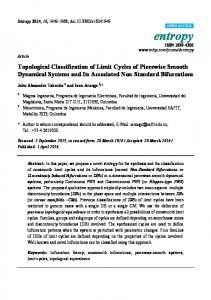
and the intersection of both curves determine the desired amplitude a of the limit cycle.
input Describing Functions (DFs) theory, together with the derivations of different type three-sinusoid-input describing functions for the ideal relay nonlinearity is given. Then the application of this approach for analysis of the limit cycles in a second order nonlinear system with ideal relay type nonlinearity is shown. An example and simulation results are presented to demonstrate the applicability of the approach.
Intersection of two curves to obtain the amplitude a 4 right curve left curve
3.5 3 2.5
Acknowledgment This work was sponsored by N.W.O., grant nr. 040.11.063.
2 1.5
References: [1] S. S. Sastry, Nonlinear Systems: Analysis, Stability, and Control, Springer-Verlag, 1999. [2] H. K. Khalil, Nonlinear Systems, 3rd Edition. Prentice-Hall, 2002. [3] A. Gelb, W. E. Vander Velde, Multiple-Input Describing Functions and Nonlinear System Design, McGraw Hill, 1968.
1 0.5 0 0.1
0.2
0.3
0.4
0.5 0.6 a -->
0.7
0.8
0.9
1
Figure 9: The Graphical solution of (29)
From Figure 9 one can obtain the amplitude a=0.3. It should be stressed that the limit cycle corresponds to the first pick in the frequency spectrum of the error signal e from Figure 8. The value of the amplitude of the limit cycle is 0.33 that is very close to predicted ones by use of the three-sinusoid-input describing function technique. Based on first equation from (26) the angular frequency of the limit cycle is (30) ωa = N a Kn + p1 p2 = 15.1606 rad/sec This result is also very close to the result obtained by the spectrum of the error signal given in Figure 8. It should be stressed that the describing functions method is an approximate procedure for study the limit cycles in nonlinear control systems and because of this the obtained results are not exactly correct. However it is very powerful tool to study the limit cycle behavior of these systems. In the presence of reference signal that consists of two sine waves, the method can be applied by using the three-sinusoid-input describing functions. In this contribution we developed simple polynomial approximations of the three-sinusoid-input describing functions for the relay nonlinearity and presented the applicability of the approach for study the limit cycles.
4 Conclusion Describing Functions method is a powerful tool for study the limit cycles in nonlinear control systems. In this contribution some results and simulations about the limit cycle prediction using three-sinusoid-input describing functions are presented. The introduction of Multiple-
ISSN: 1790-2769
47
ISBN: 978-960-474-097-0