GEOPHYSICS, VOL. 68, NO. 2 (MARCH–APRIL 2003); P. 634–640, 8 FIGS. 10.1190/1.1567233
Prestack residual migration in the frequency domain
Paul C. Sava∗ function of a nondimensional parameter γ , the ratio of the reference velocity to the updated velocity. Etgen (1988, 1990) defines a kinematic residual migration operator as a cascade of normal moveout and dip moveout; he shows that it is only a function of γ defined by Al-Yahya. Finally, Stolt (1996) defines a prestack residual migration operator in the (ω, k) domain and shows that, as in the poststack case, it depends on the reference v0 and the correct migration velocities v but not on a residual velocity vr . In this paper, I review prestack Stolt residual migration and show that it, too, can be formulated as a function of a nondimensional parameter that is the ratio of the v0 and v velocities. Consequently, we can use Stolt residual migration in the prestack domain to obtain a better-focused image without making explicit assumptions about the velocity magnitude. Although, strictly speaking, the method is developed for constant velocity, numerical examples show that it can be used in an approximate way for images migrated with smoothly varying velocity v(x, y, z), which departs from the constant velocity assumption. This method has direct application in wave-equation migration velocity analysis (WEMVA) (Biondi and Sava, 1999). In WEMVA, we invert for perturbations of the velocity model starting from perturbations of the seismic image. A quick residual migration technique is ideally suited for this task, since we are less interested in the accuracy of the perturbed images than in the direction of the change that needs to be applied to the velocity model in order to improve the image. An alternative to the residual migration technique I present is a suite of full depth migrations with velocities at a percentage change from a reference velocity. Although more accurate, such a technique is also more expensive and not much more useful than residual migration, except for a complicated geological model which violates the residual migration assumptions.
ABSTRACT
Prestack Stolt residual migration can be applied to seismic images that are depth migrated using wavefield extrapolation techniques. This method has significant advantages over other methods that estimate interval velocity functions for depth migration. It is more accurate than methods that are based on focusing the stack of migrated images by a residual NMO operation, so it provides a more accurate estimate of the correct migration velocities. Also, it is conceptually simpler and easier to implement than traveltime tomography methods. Although the theory is developed assuming constant velocity, the method can be used for depth-migrated images produced with smoothly varying velocity models, since the residually migrated images depend only on the ratio of the reference and updated velocities. This method closely resembles Stolt-stretch techniques, so it inherits the Stolt method’s speed and convenience. The main applications of this method are in migration velocity analysis (MVA), where it can be used to investigate the effects of gross velocity changes on the migrated image, and as a tool for residual image enhancement used by more sophisticated MVA methods, e.g., waveequation migration velocity analysis.
INTRODUCTION
Residual migration is useful in both imaging and migration velocity analysis. Rothman et al. (1985) show that poststack residual migration can improve the focus of migrated sections. They also show that migration with a given velocity v is equivalent to migration with a reference velocity v0 followed by residual migration with a velocity vr that can be expressed as a function of v0 and v. Residual migration has also been used in velocity analysis. Al-Yahya (1989, 1987) discusses a residual migration operator in the prestack domain and shows that it can be posed as a
THEORY
This section introduces the theory of Stolt residual migration in the prestack domain. I begin with a short discussion of
Manuscript received by the Editor January 8, 2001; revised manuscript received September 26, 2002. ∗ Stanford University, Stanford Exploration Project, Geophysics Department, Mitchell Building, Stanford, California 94305-2215. E-mail:
[email protected]. ° c 2003 Society of Exploration Geophysicists. All rights reserved. 634
Residual Migration
Stolt migration; then I derive the equations for prestack Stolt residual migration of 2D, full 3D, and 3D common-azimuth data.
Stolt migration Prestack Stolt migration can be summarized (Claerbout, 1985) as a succession of transformations from seismic data to
635
Fourier domain. Supposing that the initial migration was done with the velocity v0 and that the correct velocity is v, we can use equation (2) to derive the vertical wavenumber for the reference velocity k z0 and the vertical wavenumber for the correct velocity k z . Mathematically, the goal of prestack Stolt residual migration is to obtain k z from k z0 . If we substitute ω from k z0 to k z , we obtain the residual migration equation for full 3D prestack seismic images:
v £ ¤£ ¤ u 2 4k 2 + (|kr | − |ks |)2 4k 2 + (|kr | + |ks |)2 v 1u z z 0 0 k z = t 02 − |kr |2 2 v 16k z20 v £ ¤£ ¤ u v02 4k z20 + (|kr | − |ks |)2 4k z20 + (|kr | + |ks |)2 1u t + − |ks |2 , 2 v2 16k z20
which can also be represented in midpoint-offset coordinates using the change of variables in equation (4). In the 3D poststack case, when kh = 0, equation (5) becomes
seismic images as follows:
(t, m, h) → D(ω, km , kh ) → R(k z , km , kh ) → (z, m, h),
r
s
(1)
where and are representations of the data and image in the spatial domain, while D and R are the equivalent representations in the Fourier domain. In equation (1), t is time, m is midpoint location, h is half-offset, and z is depth. The central component of prestack Stolt migration is the remapping from the (ω, km , kh ) domain to the (k z , km , kh ) domain, where ω and k z represent the temporal frequency and the depth wavenumber, respectively, and where km = (km x , km y ) and kh = (kh x , kh y ) represent the midpoint and offset wavenumbers. If we consider the representation of the input data in shot– receiver coordinates, the mapping takes the form
1 kz = 2
1 ω2 − |kr |2 + 2 v 2
r
ω2 − |ks |2 , v2
kz =
¤ v02 £ 2 k z0 + |km |2 − |km |2 . 2 v
(6)
In the 2D prestack case (km y = 0 and km x = 0), we can write equation (5) as
v £ ¤£ ¤ u 2 k 2 + kh 2 k 2 + km 2 v 1u z z x x 0 k z = t 02 0 − (km x + kh x )2 2 v k z20 v £ ¤£ ¤ u 2 2 v02 k z20 + kh x k z20 + km x 1u t + − (km x − kh x )2 . 2 v2 k z20 (7)
(2)
For 2D poststack data, equations (6) and (7) become
s
where kr are the receiver and ks are the source wavenumbers. From equation (2) we can express ω as a function of k z :
¤£ 2 ¤ 2 2 4k z + (|kr | + |ks |)2 2 2 4k z + (|kr | − |ks |) ω =v . (3) 16k z2
kz =
£
We can obtain an equation equivalent to equation (3) in midpoint-offset coordinates if we make the usual change of variables:
kr = km + kh , ks = km − kh .
(5)
(4)
Stolt residual migration In general, residual migration improves the quality of an image without remigrating the original data; instead, a transformation is applied to the current migrated image. In prestack Stolt residual migration, we attempt to correct the effects of migrating with an inaccurate reference velocity by applying a transformation to images transformed to the
¤ v02 £ 2 2 + k k − km 2x , m z x v2 0
(8)
which can also be written in the familiar form (Stolt, 1996)
ω=
q ¡ ¢ ω02 + km 2x v02 − v 2 ,
(9)
where, by definition, ω0 = k z0 v0 and ω = k z v. Common-azimuth Stolt residual migration Common-azimuth data represent subsets of 3D prestack data that have been recorded or transformed to a common azimuth, which corresponds to zero cross-line offsets (h y = 0). Stolt migration for common-azimuth data involves the use of the following dispersion relation (Biondi and Palacharla, 1996):
kz x
1 = 2
r
1 ω2 − (km x − kh x )2 + 2 v 2
r
ω2 − (km x + kh x )2 , v2 (10)
636
Sava
where the depth wavenumber for the common-azimuth data set (k z ) is written as
kz =
q k z 2x − km 2y .
(11)
We can rewrite equations (10) and (11) for v0 and obtain the corresponding depth wavenumbers k z x 0 and k z 0 . Mathematically, the goal of common-azimuth Stolt residual migrations is to obtain k z from k z 0 . Again, we can achieve this by eliminating the frequency ω from the expressions for k z 0 and k z , which leads to the 3D common-azimuth residual migration equations:
migration velocity analysis (Biondi and Sava, 1999), where the goal is to obtain improved images regardless of the procedure used. EXAMPLES
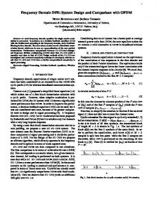
I illustrate the residual migration technique with one synthetic and one real data example. The first example is a simple 2D model with four dipping reflectors embedded in a velocity model which varies smoothly both as a function of horizontal position and as a function of depth. Figure 1 shows, from top to bottom, the slowness
v £ ¤£ ¤ u 2 u v k z 20 + km 2y + kh 2x k z 20 + km 2y + km 2x 1 0 t − (km x − kh x )2 kz x = 2 2 2 2 v k + k z m 0 y v £ ¤£ ¤ u 2 2 2 2 2 2 2 v0 k z 0 + k m y + k h x k z 0 + k m y + k m x 1u t + − (km x + kh x )2 2 v2 k z 20 + km 2y q k z = k z 2 − km 2 . x y For 2D data, where km y = 0, k z ≡ k z x , and k z 0 ≡ k z x 0 , equations (12) reduce to the 2D prestack [equation (7)] and poststack [equation (8)] forms. DISCUSSION
We now know we can formulate prestack Stolt residual migration without directly assuming the new velocity to which we residually migrate the data. Instead, we can select a ratio of the current velocity to the updated one (γ = v0 /v). This conclusion is true in the 3D case [equations (5) and (6)] the 2D case [equations (7) and (8)], and the case of 3D common-azimuth data [equation (12)]. Stolt (1996) comments that, in the poststack case, the frequency after time migration can be related to the frequency of the original data and the difference of the squares of the two velocities, before and after residual migration [equation (9)]. However, he also shows that such a conclusion is no longer true in the prestack case. If we reformulate Stolt residual migration as a function of the ratio of two velocities, we can apply the process to images which have been depth migrated with arbitrary velocity models. This is technically possible because the equations do not operate with velocity differences but with velocity ratios. The residual migration transforms using a scaled version of the original velocity field. In this formulation, prestack Stolt residual migration is a constant-velocity ratio method, not a constant velocity method. It is important to understand that this approach is an approximation and may not work in regions of extreme complexity and large velocity contrasts. Furthermore, the method is correct only from a kinematic point of view and does not incorporate amplitude corrections. An extension of this method can go beyond constant velocity ratios. Since it is a fast, Stolt-type technique, we can run a large number of different residual migrations at different velocity ratios and then pick the values of the ratio parameter γ (x, y, z) that give the best image at every location in space. This method is therefore a good companion to wave-equation
(12)
model, the reflectivity model, and the zero offset of the 2D modeled data. The data were generated with a wavefieldcontinuation operator (Claerbout, 1985; Ristow and Ruhl, 1997; Le Rousseau and de Hoop, 1998). The maximum offset of the simulated data is 2.56 km, and the velocity ranges between 2.0 km/s in the upper-left corner to 2.4 km/s in the lower-right corner. To test the prestack Stolt residual migration, I migrate the synthetic data using the wavefield-continuation method with the mixed-domain split-step Fourier method. The tests are conducted using two velocity models: the correct velocity and an incorrect velocity model, obtained from the correct one by scaling with a factor of 0.8. Figure 2 shows the image obtained using the correct velocity model. The left panel represents the zero-offset section of the image obtained by 2D prestack downward-continuation migration. The right panel represents a common image gather (CIG) in the angle domain (Sava et al., 2001), extracted at the horizontal location x = 1 km. Figure 3 shows the image obtained using the incorrect velocity model. Since this velocity is smaller than the correct one, the image is strongly undermigrated and the events in the angledomain CIGs bend strongly upward. Figure 4 shows the result of applying Stolt residual migration using the correct velocity ratio (γ = 0.8) to the undermigrated image in Figure 3. The result is a well-focused image with reasonably flat angle gathers. This result shows that, although only approximate for variable velocity media, the method outlined in this paper can successfully operate on depthmigrated images despite the assumption of constant velocity made in the derivation. Of course, there is no guarantee that the method will be successful on arbitrary velocity models. However, on fairly smooth models, Stolt residual migration can at least indicate the direction of the changes that improve the migrated image. The second example concerns a real data set from a complex salt dome region in the North Sea. Figure 5 shows a zerooffset section obtained by 2D prestack downward-continuation
Residual Migration
migration. We can clearly distinguish the salt body and the sediment layers. However, the area under the salt overhang is not imaged correctly, mostly because of the inaccuracies in the velocity model (Vaillant et al., 2000). The errors in this image are too complex for a simple algorithm like the one outlined in this paper to be fully successful.
637
We cannot hope to recover the exact structure under the salt overhang just by residual migration. However, we can use the speed of such an algorithm to investigate whether any other piece of the image can be brought in focus and to determine roughly in which direction we need to modify the velocity model. Figure 6 shows the result of residual migration. Each one of the nine panels corresponds to the box depicted in Figure 5. The images are obtained for various values of γ ranging from γ = 1.0 in the lower-right corner to γ = 0.92 in the upper-left corner.
FIG. 2. Migrated image (zero offset section) and angle-domain CIG for the synthetic data in Figure 1 obtained using the correct velocity model.
FIG. 3. Migrated image (zero-offset section) and angle-domain CIG for the synthetic data in Figure 1 obtained using the incorrect velocity model scaled by γ = 0.8.
FIG. 1. Synthetic model. (top) Slowness model; (middle); reflectivity model; (bottom) zero-offset section of the modeled 2D prestack data.
FIG. 4. Residually migrated image (zero-offset section) and angle-domain CIG for the synthetic data in Figure 1 obtained from the image in Figure 3 after residual migration with the correct velocity ratio γ = 0.8.
638
Sava
We can observe several things. First, the top of salt, which was not well focused in the original image (γ = 1.0), is better focused in some of the panels corresponding to lower values of the parameter γ . Second, the salt overhang is brought into much better focus, particularly in the panel corresponding to γ = 0.94 around x = 6000 and z = 3000. Third, the sediments
that are practically impossible to track in the original image are more coherent and can be traced much deeper under the salt overhang on the image corresponding to γ = 0.94. Figure 7 is a comparison between the original image (γ = 1.00, top panel) and the image obtained by prestack Stolt residual migration that best resolves the salt overhang and
FIG. 5. Migrated image of the North Sea data. The area of interest is surrounded by the thick box.
FIG. 6. Prestack Stolt residual migration for a range of velocity ratio parameters γ from 1.0 in the lower-right panel to 0.92 in the upper-left panel. All panels correspond to the box in Figure 5.
Residual Migration
639
sediments underneath (γ = 0.94, bottom panel). For comparison, the middle panel shows an image obtained by residual moveout, which also shows an improvement over the original image, but not as good as the one obtained by residual migration. This is understandable, since residual moveout does
not allow energy to move between midpoints while residual migration does. Finally, if we carefully analyze the images in Figure 6, we can observe that various parts of the image are in good focus at different values of γ . This leads to the conclusion that none of
FIG. 7. A comparison of the original image (top) with the improved images obtained by residual moveout (middle) and the image after residual migration with a constant velocity ratio parameter γ = 0.94 (bottom). All panels correspond to the box in Figure 5.
FIG. 8. A comparison of the original image (top) with the image obtained by residual migration (middle) with a spatially varying γ . The velocity ratio parameter γ is ranging from 0.91 to 1.00 (bottom). All panels correspond to the box in Figure 5.
640
Sava
the panels in Figure 6 can serve alone as an improved image at all locations in the image. One possible solution to this problem is to create a smooth interpolation map which slices through the various images at different values of γ for every location in the image. Figure 8 shows such a result: the top and middle images are, respectively, the original and improved images for variable γ , and the bottom panel is the interpolation map used to extract the middle panel. In summary, a cheap algorithm like the one I outline allows us to successfully investigate and enhance images that have been migrated using sophisticated depth migration methods. These images are not the final solution. For that, we must update the velocity model using tomography and remigrate the data. These additional steps, however, fall outside the scope of this paper. CONCLUSIONS
We can reformulate prestack Stolt residual migration such that it becomes applicable to depth-migrated images. In essence, the residual migration introduced here is a Stoltstretch method; therefore, it retains both the advantages and the disadvantages of Stolt-type techniques. The main benefit of this method is that we can residually migrate by assuming given ratios between the current and updated velocities, rather than fixing the new velocities directly. In this way, we can apply Stolt residual migration to images that have been migrated with an arbitrary velocity map, not just to those migrated with constant velocity. This result is not exact, but practice shows that it is feasible for smoothly varying media. This conclusion is valid for all types of seismic images, from 2D poststack to 3D prestack, including 3D common azimuth. The method is cheap to apply; therefore, one of its main uses is in the area of repeated residual image enhancement, with applications to wave-equation migration velocity analysis
(Biondi and Sava, 1999) or as a simple technique to create velocity maps in field exploration. ACKNOWLEDGMENTS
Thanks to TotalFinaElf for providing the salt dome data used in this paper. Also thanks to the associate editor, Samuel Gray, and the reviewers, Robert Stolt and Helmut Jakubowicz, whose comments significantly improved this paper. REFERENCES Al-Yahya, K., 1987, Velocity analysis by iterative profile migration: Ph.D. thesis, Stanford Univ. ———1989, Velocity analysis by iterative profile migration: Geophysics, 54, 718–729. Biondi, B., and Palacharla, G., 1996, 3-D prestack migration of common-azimuth data: Geophysics, 61, 1822–1832. Biondi, B., and Sava, P., 1999, Wave-equation migration velocity analysis: 69th Ann. Internat. Mtg., Soc. Expl. Geophys., Expanded Abstracts, 1723–1726. Claerbout, J. F., 1985, Imaging the earth’s interior: Blackwell Scientific Publications, Inc. Etgen, J., 1988, Velocity analysis using prestack depth migration: Linear theory: 58th Ann. Internat. Mtg., Soc. Expl. Geophys., Expanded Abstracts, Session: S9.7. ———1990, Residual prestack migration and interval velocity estimation: Ph.D. thesis, Stanford Univ. Le Rousseau, J., and de Hoop, M., 1998, Modeling and imaging with the generalized screen algorithm: 68th Ann. Internat. Mtg., Soc. Expl. Geophys., 1937–1940. Ristow, D., and Ruhl, T., 1997, 3-D implicit finite-difference migration by multiway splitting: Geophysics, 62, 554–567. Rothman, D. H., Levin, S. A., and Rocca, F., 1985, Residual migration— Applications and limitations: Geophysics, 50, 110–126. Sava, P., Biondi, B., and Fomel, S., 2001, Amplitude-preserved common image gathers by wave-equation migration: 71st Ann. Internat. Mtg., Soc. Expl. Geophys., Expanded Abstracts, 296–299. Stolt, R. H., 1996, Short note—A prestack residual time migration operator: Geophysics, 61, 605–607. Vaillant, L., Sava, P., Biondi, B., and Calandra, H., 2000, 3-D waveequation migration of a common-azimuth North Sea dataset: 62nd Mtg., Eur. Assn. Geosci. Eng., Abstracts, 231–235.