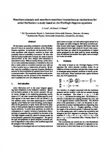
It is very important to analyse phase ingomogenity of high-power laser beam. Usually Shack-Hartmann wavefront sensor or interferometer is used to test both ...
Problem of Shack-Hartmann wavefront sensor and Interferometer use while testing strongly distorted laser wavefront Julia Sheldakova, Alexis Kudryashov, Vadim Samarkin, Valentina Zavalova Moscow State Open University, Adaptive Optics Laboratory Sudostroitelnaya Str 18, Bld. 5, Moscow, Russia 115407
ABSTRACT It is very important to analyse phase ingomogenity of high-power laser beam. Usually Shack-Hartmann wavefront sensor or interferometer is used to test both laser beam aberrations and quality of the optical element surface. But we found out that in case of strong distortions the measured aberrations differ from the real ones. To investigate this problem we used bimorph deformable mirror to introduce strong aberrations to the laser beam. The results of our experiments are discussed. Keywords: Shack-Hartmann wavefront sensor, interferometer, laser beam measurements
1. INTRODUCTION While use of high power laser beam the user faces a problem of strong aberrations. The most of aberrations are caused by the optical elements and ingomogenity of surrounding medium. To improve the laser beam an adaptive optical system could be used [1]. The standard adaptive optical system consists of a wavefront corrector, an electronic control unit, a sensor to measure wavefront, and software to determine the control signals to be applied to the corrector. As a corrector we use bimorph deformable mirrors because such mirrors have very high damage threshold and could be installed in high power laser system [2]. To understand how to measure strong deformations of the wavefront we decided to represent overall defocus by deformable mirror and to measure introduced defocus with number of methods: 1. Direct focal length measurement; 2. Indirect focal length measurement with the application of focusing lens; 3. Shack-Hartmann technique; 4. Interferometery. The results of experiments are discussed in this paper.
2. DESIGN OF THE DEFORMABLE MIRROR Deformable bimorph mirror is a multilayer round disc: first disc, which is polished and deposited with the high reflecting coating, is made of optical glass material; another two discs are made of piezoceramic material PZT. Each disc is firmly glued to another one (Fig. 1). Glass substrate
El. #1 (defocus) El. ## 2-32
PZT discs Fig. 1. Schema of the bimorph mirror
Laser Resonators and Beam Control X, edited by Alexis V. Kudryashov, Alan H. Paxton, Vladimir S. Ilchenko, Proc. of SPIE Vol. 6872, 68720B, (2008) · 0277-786X/08/$18 · doi: 10.1117/12.774086
Proc. of SPIE Vol. 6872 68720B-1 2008 SPIE Digital Library -- Subscriber Archive Copy
First PZT disc, which has the all-round electrodes, serves for curvature deformation of the mirror surface (it reproduces defocus). To reproduce different types of aberrations the outer surface of the second PZT disc is divided in several control electrodes, which have the shape of part of the sector (Fig. 2).
D1 = 8 мм D2 = 21 мм D3 = 35 мм D4 = 45 мм
Fig. 2. Schema of electrodes configuration for 32-channels mirror
When deformable mirror is designed and produced the deformation characteristics should be also investigated. The main parameters of deformable mirror are response functions. Response function of electrode of the deformable mirror represents the modification of surface profile of the mirror while unit voltage is applied to single electrode. Usually we measure response functions of the mirror with Shack-Hartmann wavefront sensor or Fizeau interferometer. But if the mirror is very sensitive and its response is rather big the result of measurements is unpredictable. For the experiments described in this paper we used a mirror with diameter of 50 mm and 32 electrodes. Initially the mirror surface was flat. Then we applied -190 V on each electrode of the mirror and measured the curvature of the mirror (or focal distance). The results of the measurements are presented below.
3. MEASUREMENTS OF THE FOCAL LENGTH First we placed mirror under collimated He-Ne laser beam, and introduced curvature by applying voltages of -190V on each electrode of the mirror. The shape of the mirror under this voltage is presented on Fig. 3. -190 V
Fig. 3. Shape of the mirror We found out that the focal plane under -190 V was on the distance of 8.4 m from the mirror (Fig. 4). Deformable mirror
He-Ne
F=8.4 meters Fig. 4. Experimental setup
Proc. of SPIE Vol. 6872 68720B-2
To measure the dependence of the mirror focal length versus voltages we installed an additional focusing lens (F=350 mm) and smoothly applied voltages to the mirror electrodes; then the focal length of the mirror was recalculated according to the measurements of the distance D ( Fig. 5). The results of measurements are presented on Fig. 6. The focal distance under -190V is 8.45 m; this result is well agreed with the direct focal length measurements. The result of indirect measurements depends upon the error of measurement of the distance between the additional focusing lens and the focal plane. In case we measured this distance with the error of 1 mm the focal length becomes 0.3 m smaller (or bigger). So we should measure the distance from lens to the focal plane very precisely. And this task is rather difficult because we even hardly can define the secondary principal point of the introduced lens. But if we can measure the distance with high precision and also determine the secondary principal point position correctly – the error is reasonable. Deformable mirror
He-Ne D f=350 mm Fig. 5. Experimental setup
40 30 20
ID. -200
-150
-100
-50
0
Voltages, V Fig. 6. Dependence of the mirror focal length versus voltages
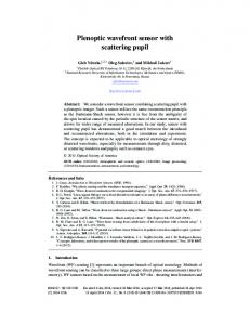
4. CURVATURE MEASUREMENTS WITH FIZEAU INTERFEROMETER To measure the aberrations with interferometer one could use Fizeau interferometer [3] made by ZYGO Corp. or by Active Optics Ltd., for example. In case of any Fizeau interferometer the mirror surface is conjugated to imaging system of the interferometer (Fig. 7). Here conjugated planes are indicated as doted lines. So if we measure rather small aberrations the result is always correct. To define the deformation of the mirror we used interferometer Fizeau RIF-100 that was produced and designed in our laboratory. The software that we developed is intended to process interference patterns with additionally introduced tilt. It was possible to measure the deformation under -40 V on all channels (P-V=3.5 µ). To obtain the data for voltage of 190 V we measured Zernike coefficient #3 (defocus) in the range of 0 V ÷ -40 V and then extrapolated the results of measurements. After that we recalculated P-V; the result is presented on Fig. 8. Calculated focal length of the mirror under the voltage of -190 V was 11.2 m. This value is much higher than the really measured focal distance of 8.4 m. It means that with extrapolation we cannot obtain the correct result. While focal length calculation it was very critical to define the diameter of the mirror correctly. The dependence of the calculated focal distance versus diameter is presented on Fig. 9. The measured focal distance in chapter 3 corresponds to 43.4 mm of mirror diameter. It could mean that the mirror surface is not conjugated to the interferometer measuring camera in case of large aberrations of the measured wavefront.
Proc. of SPIE Vol. 6872 68720B-3
Wedge
Focusing lens
Deformable mirror
Mirror
Beam splitting cube
Imaging system
HeNe
P_V lOPE aiwl
Ziike 3 iiErci is
I
Fig. 7. Experimental setup with Interferometer Fizeau
Fig. 8. P-V and Zernike 3 measured with interferometer
13 12
II ID 9 8 7
tr44 40
45
50
Diaiiieter, 111111
Fig. 9. Focal distance versus diameter
Proc. of SPIE Vol. 6872 68720B-4
5. SHACK-HARTMANN WAVEFRONT SENSOR TO MEASURE STRONG ABERRATIONS The principle of Shack-Hartmann wavefront sensor is shown on Fig. 10; the measurements are based on determination of local slopes ∆S of a distorted wavefront [4]. The main elements of the sensor are lenslet array and CCD (or CMOS) camera. In our adaptive optical systems we use a focusing lens to fit the beam size to the CCD. But in order to measure the aberrations correctly the mirror surface should be conjugated to the lenslet array. In this case a telescopic system should be used to match the beam size to the CCD. The scheme of the setup is presented on Fig. 11.Conjugated planes are indicated as doted lines. Lenslet array ∆S Laser beam
Fig. 10. Idea of Shack-Hartmann wavefront sensor
The dynamic range of the sensor allowed us to measure maximal deformation of 6.5 µ. The overall deformation under 190V was 25 µ that corresponds to focal length of 6.25 m (for 50 mm of the mirror diameter). Again in this case the focal distance depends upon the determination of mirror diameter; really measured focal distance corresponds to 58 mm of mirror diameter. This might be because the mirror surface became not conjugated to the sensor when strong aberrations are introduced.
Deformable mirror
He-Ne Telescope
Lenslet array
CCD
Fig. 11. Experimental setup with Shack-Hartmann wavefront sensor
6. DISCUSSION The results of all measurements are presented on Fig. 12. We can see that all the obtained results differ from each other. Both interferometer and Shack-Hartmann wavefront sensor give incorrect results. The results of direct and indirect measurements are close to each other.
Proc. of SPIE Vol. 6872 68720B-5
The best way to measure large defocus is to measure it directly or with additional optics. In case of strong aberrations in interferometer and Shack-Hartmann wavefront sensor the plane of the mirror and the sensor are not conjugated – that is the main problem. 1)
2)
25.1 20.1 3)
15.I 4)
10.1
-200.00
-150.00
-100.00
-50.00
0.00
VcItag V Fig. 12. Comparison of all measurements. 1) Shack-Hartmann sensor, 2) Direct measurements, 3) Indirect measurements, 4) Interferometer
REFERENCES 1. 2. 3. 4.
A.L.Rukosuev, A.Alexandrov, V.Ye.Zavalova, V.V.Samarkin, A.V.Kudryashov, "Adaptive optical system based on bimorph mirror and Shack-Hartmann wavefront sensor", Proc. SPIE 4493, pp. 261-268, 2002. J.C.Dainty, A.V.Koryabin, A.V.Kudryashov, "Low-order adaptive deformable mirror", Appl. Opt. 37(21), pp.4663-4668, 1998. E.P.Goodwin, J.C.Wyant, "Interferometric optical testing", SPIE Press, Bellingham, Washington USA, 100 p., 2006. V.Ye.Zavalova, A.V.Kudryashov, "Shack-Hartmann wavefront sensor for laser beam analyses", Proc. SPIE 4493, pp. 277-284, 2002.
Proc. of SPIE Vol. 6872 68720B-6