Aspect-Oriented and Model-Driven Software Development. Markus Voelter. 1 ...
Software product line engineering aims to reduce development time, effort, cost, ...
Product Line Implementation using Aspect-Oriented and Model-Driven Software Development Markus Voelter1, Iris Groher2 1 Independent Consultant, Heidenheim, Germany 2 Siemens AG, CT SE 2, Munich, Germany
[email protected],
[email protected] Abstract Software product line engineering aims to reduce development time, effort, cost, and complexity by taking advantage of the commonality within a portfolio of similar products. The effectiveness of a software product line approach directly depends on how well feature variability within the portfolio is implemented and managed throughout the development lifecycle, from early analysis through maintenance and evolution. This paper presents an approach that facilitates variability implementation, management and tracing by integrating model-driven and aspect-oriented software development. Features are separated in models and composed by aspect-oriented composition techniques on model level. Model transformations support the transition from problem to solution domain. Aspect-oriented techniques enable the explicit expression and modularization of variability on model, code, and template level. The presented concepts are illustrated with a case study of a home automation system.
1
Introduction and Motivation
Most high-tech companies provide products for a specific market; thus the products have many things in common. An increasing number of these companies realize that product line development [1,2] fosters reuse at all stages of the lifecycle, shortens development time and helps staying competitive. The effectiveness of a software product line approach directly depends on how well feature variability within the portfolio is managed from early analysis to implementation and through maintenance and evolution. Commonalities, as well as the flexibility to adapt to different product requirements are captured in core assets. Those reusable assets are created during domain engineering. During application engineering, products are either automatically or manually assembled, using the assets created during the domain engineering process and completed with product-specific artifacts. Products usually differ by the set of features they include in order to fulfill customer requirements. A feature is an increment in functionality provided by one or more members of a product line [3].
Variability management is the activity concerned with identifying, designing, implementing, and tracing flexibility in software product lines (SPLs). Variability of features often has widespread impact on multiple artifacts in multiple lifecycle stages, making it a predominant engineering challenge in software product line engineering (SPLE). In traditional SPLE approaches, variability is mainly handled using either mechanisms provided by the implementation language, such as patterns, frameworks, polymorphism, reflection, and pre-compilers or using configuration and build tools to set compile time variables and select variants of assets. The approach described in this paper facilitates variability implementation, management, and tracing from architectural modeling to implementation of product lines by integrating both model-driven (MDSD) and aspect-oriented software development (AOSD). For companies that are already building product lines, MDSD and AOSD can further increase productivity because: Variability can be described more concisely since in addition to the traditional mechanisms, variability is also described on model level. The mapping from problem to solution domain can be formally described automated using model-tomodel transformations. Aspect-oriented techniques enable the explicit expression and modularization of crosscutting variability on model, code, and generator level. Fine grained traceability is supported since tracing is done on model element level rather than on the level of code artifacts. The presented concepts are illustrated with a case study of a home automation system. The case study is based on real-world system requirements from Siemens AG and demonstrates the benefits of the presented approach. The rest of the paper is organized as follows: Section 2 introduces model-driven and aspect-oriented development and explains the building blocks of the approach. Section 3 describes the case study. Section 4 looks at tool support. Related work is discussed in Section 5, while Section 6 summarizes the paper and provides an outlook on future work.
2
Concepts and Building Blocks
Model-driven software development (MDSD) [4] improves the way software is developed by capturing key features of a system in models which are developed and refined as the system is created. During the system’s lifecycle, models are synchronized, combined and transformed between different levels of abstraction and different viewpoints. In contrast to traditional modelling, models do not only constitute documentation but are processed by automated tools. Thus models have to be formal, whereas every model is an instance of a meta model. The meta model defines the vocabulary and grammar, i.e. the abstract syntax, used to build models. In order to be useful for MDSD, models have to be complete regarding the abstraction level or viewpoint they describe. A Domain Specific Language (DSL) [4] is a formalism for building models: It encompasses a meta model as well as a definition of a concrete syntax that is used to represent the models. The concrete syntax can be textual, graphical or using other means, such as tables, trees or dialogs. Different DSLs can use the same meta model while varying in their concrete syntax. The models built with these DSLs will look different, but will all have the same meaning. The meta model is what the tools care about, whereas the concrete syntax is what the DSL users care about. It is essential, that the concrete syntax can sensibly represent the concepts the DSL is intended to describe. Aspect-oriented software development (AOSD) [5,6] improves the way software is developed by providing means for modularizing crosscutting concerns. They are encapsulated as aspects and powerful mechanisms support their subsequent composition with other software artefacts. Aspects interfere with other artefacts at so called join points, well defined points in the structure or execution flow of an artefact or a program. Pointcut expressions quantify over the join points to select the set of actual composition points for a specific aspect. An aspect weaver automatically composes aspects with the rest of the system, either statically during compilation, dynamically at runtime, or at load-time. While MDSD and AOSD are different in many ways – MDSD adds domain specific abstractions and AOSD offers concern modularization and composition mechanisms – they also have many things in common. Existing research has investigated ways of combining the two paradigms [7,8,9,10] to achieve the complementary benefits of both MDSD and AOSD. This paper explores an approach that integrates model-driven and aspect-oriented techniques in order to facilitate variability implementation, management and tracing in SPLE.
The general approach we are going to propose is as follows: Express as many artifacts as possible using models as this allows for processing these artifacts using model transformations. Mappings from problem to solution domain are implemented as model-to-model (M2M) transformations. This enables to formally describe mappings and automate their execution. Variable parts of the resulting system are either assembled from pre-build assets generated from models or implemented via interpreters. This is more efficient and less error-prone than manual coding in a third generation language (3GL). Aspect-oriented modeling (AOM) [8,11] is used to implement variability in models. This supports the selective adaptation of models. Aspect-oriented programming (AOP) [12,13] is used to implement crosscutting features on code level that cannot easily be modularized in the generator. Certain parts of a product will still be implemented manually because, for economic reasons, developing a custom generator is too costly. The manually written code is integrated with the generated code in well-defined ways. In the following sections we will describe these steps in more detail.
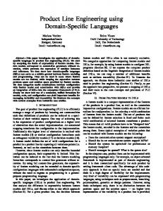
2.1 Kinds of Variability In the context of product line engineering, DSLs are used to bind variability. We distinguish between two kinds of variability: structural and non-structural. Structural variability is described using creative construction DSLs, whereas non-structural variability can be described using configuration languages. Figure 1 illustrates the spectrum of languages commonly used for expressing and binding variability.
Figure 1. Expressive power of DSLs
Figure 2 shows the meta model of a creative construction DSL. Any number of models can be defined, by instantiating meta model elements. Figure 3 presents an example using the familiar concrete syntax of UML. Figure 4 shows a feature model of a weather station using the notation defined in [15]. The feature model expresses a certain configuration space, i.e. the model is an expression of configurative variability. A specific
configuration is described by selecting a valid subset of those features.
called mixin models to parameterize the transformation or to provide the additional data required.
2.3 Expressing Variability in Models
Figure 2. Creative construction meta model
To align feature modeling with general MDSD terminology, it is useful to consider the feature model a meta model and the concrete configurations models.
We have shown that there are two fundamentally different kinds of variability, and consequently, two different kinds of DSLs: creative construction DSLs and configuration DSLs. We have also shown that in MDSD-based SPLE, models are used to represent products in the problem and solution domain. Consequently, a solution domain model often needs to be adapted based on a product configuration in the problem domain. In other words, we want to use a configuration model to define variants of a model built with a creative construction DSL.
Figure 3. Example models
2.2 Problem/Solution Domain Mapping In SPLE, two areas of concern can be distinguished: the problem domain and the solution domain. The former is concerned with end-user understandable concepts while the latter deals with the implementation of the product features using software technologies.
Figure 5. Negative (a), positive (b) variability
There are two fundamentally different ways of approaching this problem: One can either use negative variability or positive variability (see Figure 5). Negative variability selectively takes away parts of a creative-construction model based on the presence or absence of features in the configuration models. The “overall” model is built manually, and model elements in that model are connected to features in the configuration model. Figure 6 shows an example.
Figure 4. Weather station feature model
When using MDSD for implementing product lines, we use DSLs in both domains to express the respective variability. Often, we use configuration DSLs in the problem domain and creative construction DSLs in the solution domain, although there are also examples to the contrary. Central to SPLE is the specification of product features in the problem domain, and their subsequent mapping to corresponding solution domain features. Since we use DSLs in both domains, we can use modeltransformations to automate this mapping. A model transformation takes a source model M and transforms it into a target model K. M and K are typically instances of different meta models and reside at different levels of abstraction. The source model M is not modified during the transformation. In the context of SPLE, M is typically the problem domain model and K is the solution domain model. The problem domain model might not contain all the information necessary for the transformation to populate the solution domain model. Hence we use so-
Figure 6. Model variants
The second alternative uses positive variability. We start with a minimal core and selectively add additional parts. For this to work, one has to specify where the new parts should be attached. Here aspect weaving on model level comes into play: Optional parts are woven into the core. A pointcut expression defines the “con-
nection points”. We call this approach model weaving, an example of aspect-oriented modeling. We elaborate on tool support for model weaving in Section 4.
2.4 Tracing An important concern in SPLE is traceability as stakeholders want to be able to trace how a given requirement results in a certain software configuration. Using MDSD-SPLE, this is relatively easy to do. Since mappings between abstraction levels are based on formal model transformations, we can make sure the mappings are made persistent in a trace model. It can either be built automatically by the transformation engine, or it can be built manually by the transformation developer (by calling some kind of createTrace(fromElement, toElement, traceKind) function in the transformation script at the appropriate locations). We prefer the second approach since it allows developers to control trace granularity. Two things are worth mentioning here: Since we trace between model elements, the trace is finer grained than in current approaches, where tracing happens between artifacts [16,17]. Since problem domain concepts are also represented as models, we gain traceability from the problem domain over to the solution domain. Additionally, we need to trace down to code level. Specific regions of code need to be associated with model elements. For generated code, this is straight forward since the generator knows which model elements are “in scope” when a given region of code is generated. For manually written code it is more challenging, since a piece of hand-written code may implement any number of requirements. This problem can be mitigated to some extent by clearly defining the locations where manually written code can be integrated. An alternative approach is to specify the trace from code to models manually. On the other end of the spectrum we also need to trace requirements. These are different from problem domain models as requirements are typically plain English. To make them traceable, we need to somehow integrate them into the “modeling world”. This can be done in various ways, depending on the tool that is used to capture the requirements. For example, it would be possible to create an EMF model [24] based on requirements managed with the DOORS [40] tool and use the EMF model for tracing purposes. Finally, we need to trace to library components. This is relatively easy to do if we assume that every library component has some kind of representation on model level. We can then trace via model element relationships (more on this in the next section).
2.5 Library Components Core assets are reusable artifacts that can be utilized in some or all products in the product line. We distinguish core assets from library components. The former includes generators, meta models and other artifacts involved in the construction of the products, the latter are strictly part of the products themselves. This section focuses on library components only. Based on the information in the models, we can determine whether a given library component is part of a product. Library components can come in three flavors: implemented purely in code, as pure models and implemented in code, but accompanied by models. If the facet of the PL that is covered by the library component is not supported generatively, the component has to be pre-built and included as code. The production process for the product will simply include/link/instantiate/deploy the component if it is required. Example: An optional SNMP monitoring agent running on a system node. The other extreme is that the SPL contains generators that can completely generate the component implementation. Here it is preferable to include only the model into the library because, if the generator changes, the library component’s implementation is automatically adapted (since it’s regenerated). Example: A reusable business process component specified as a component with an associated state machine. A mix of the two approaches is appropriate if some facet of a component can be represented via a model, while another facet cannot. For example, in a component-based architecture, one might have a logging component pre-manufactured and implemented. In order to be able to instantiate and connect it, there has to be a model for the component. In that case, the library contains the implemented component (or at least those parts that are not generated and have to be manually implemented) as well as the model fragment that describes it (typically its external interfaces, etc.).
2.6 Target Code Variability In a generative environment (as opposed to an interpreted world) it is the generated code that ultimately counts. At some point we have to leave the “modeling world” and use code generation templates (or some other code generation technology [18]) to generate the product source code. There are two extremes as to when to leave the modeling world and generate code: Direct model-to-code generates code from the model the user created (in our case the problem domain model). The code generation tool must be
quite powerful, since the abstraction gap is large and has to be bridged in one step, using the code generator only. The other extreme is to consider source code a model, and use M2M transformations to instantiate the abstract syntax tree of the target language. Code generation is then extremely simple, since it is only a form of un-parsing (or pretty printing). This approach results in complex M2M transformations. In our experience, the truth lies somewhere in the middle and based on experience rather than hard facts. Typically, we stay on model level as long as structural variability in the models has to be taken care of. Once the only remaining variability is with respect to the generated text (e.g. code, configuration files) we will handle the remaining variability in the templates. In order to address this kind of variability, a means of handling variability in templates is necessary. Using AO on templates, we can isolate template-based variability into template aspects. We will elaborate on tool support for AO on template level in Section 4.
2.7 Architectural (Meta) Models MDSD also helps with the representations of architectures in SPLE. We distinguish between two kinds of architectures: The product line architecture is the overall architecture of all the software involved in building the products. It also includes the “meta artifacts” (generators, DSLs, transformers etc.). The target architecture describes the architecture of the products built with the product line architecture. In this section we want to focus on the target architecture only.
application engineering this meta model is instantiated to represent the concrete architecture of a given product. Figure 7 illustrates a simple meta model for the type viewpoint of a hierarchical component architecture. Based on this architectural meta model, a (simplistic) product architecture can be defined (see Figure 8).
Figure 8. Example product architecture
The architectural meta model defined during domain engineering defines a (formal) vocabulary that can be used for defining product architectures.
2.8 Runtime Variability The discussions above assume that the binding time for the variability is during code generation. However, not all variability in a product line can or should be bound at generation time. Deployment-time, load-time and runtime variability need to be considered as well. The mechanisms for achieving these are wellknown: frameworks, dynamic instantiation, parameterization, reflection and interpreters together with some kind of data that shall be consumed by frameworks and interpreters. There are two important connections to MDSDSPLE that need to be made here. The “data” is of course a model. Instead of feeding (some of the) models describing the product into the code generator, we include the model into the product and feed it into frameworks and interpreters. We also provide a means to edit the models while the application runs. The runtime variability needs to be configured consistently with the overall requirements and the product. The parameterization needs to be derived somehow from the models. This means that configuration files for frameworks are typically generated. This approach is especially relevant for 3rd-party frameworks that expect some kind of (often XML-based) configuration file.
2.9 AOP on code level
Figure 7. Meta model for type viewpoint
It is often said colloquially, that, during domain engineering an architecture is defined that is instantiated during application engineering. This instantiation step can be understood literally in the context of MDSDSPLE. During domain engineering an architectural meta model is created for use in the solution domain. In
In the preceding paragraphs we mainly discussed models. We also discussed AOSD in the context of models, i.e. model weaving. In this section we focus on AO on code level in the context of MDSD-SPLE. Of course we can simply generate code in an AO language as opposed to a traditional 3GL. After the code generation, the compiler/weaver builds the binary program. A particularly useful approach uses abstract aspects (aspects whose pointcuts are not fully specified). The core assets of the product line contain a manually written abstract aspect. Based on the product configuration, the generator generates concrete sub-
aspects. These contain generated pointcuts, deciding if and where to weave the advice. Since an AO language provides greater expressive power than a traditional language, the code generation templates become simpler. Architects need to decide on the tradeoff between simpler templates and introducing the additional complexity of an AO language. Another way of using AO on code level is to generate configurations for AO frameworks, such as a Spring configuration file [19] or a POA configuration using CORBA interceptors [20]. While this is conceptually similar to generating pointcuts, it is technically different and thus deserves separate mentioning. Finally, there is a third and maybe most important way of exploiting AOP in MDSD-SPLE. A product line architecture needs to have predefined variation points (or hooks) in all the locations where product specific variation can occur. However, for a given new product, the product line architecture may not provide the required configuration or customization hooks. There are two ways out of this dilemma: Either one has to manually tweak the generated code to accommodate the variant, or the product line architecture has to be adapted to include the additional hook(s). The latter approach is desirable, but for reasons of versioning, coordination or time pressure it is often not realistic. Here is where AOP comes into play. Using AO languages such as AspectJ [12], one can hook into generated (or manually written library) code at places where the product line architecture does not provide hooks. Thus the necessary change can be accommodated without changing the product line architecture and without manually changing the generated code – the change is “external” in the aspect. In some sense this is still a tweaking of the generated system, and it is a good idea to subsequently refactor the product line architecture to include proper hooks.
2.10
Meta-Product Lines
It is also possible to build product lines of product line architectures. This may sound strange, but is a very useful thing (we will illustrate this in our case study). So what does this actually mean? If a product line architecture uses meta models, transformations, generators and DSLs including custom editors, then a meta product line builds variants of these artifacts. In order to do this the following has to be done: Variants of meta models have to be built (e.g. using the techniques introduced in Section 2.3). Corresponding variants of editors have to be defined. Editors are often defined using models, too, so this task is again one of model variation. Reusable generator components, also known as cartridges, have to be built.
The generator has to be configured, e.g. the transformation steps it executes. Again, AO can be used on generator level, i.e. AO on template and on model transformation level. An example of (meta) model customization is the meta model in Figure 7. The model elements with the grey background are those necessary for hierarchical components as opposed to flat ones. Expressing hierarchical components is thus an optional feature of the component architecture. The necessary additional model elements can be woven into the meta model.
3
Case Study: Home Automation
The case study to illustrate our approach is a home automation system (see also [1]), called Smart Home. In homes you will find a wide range of electrical and electronic devices such as lights, thermostats, electric blinds, fire and smoke detection sensors, white goods such as washing machines, as well as entertainment equipment. Smart Home connects those devices and enables inhabitants to monitor and control them from a common UI. The home network also allows the devices to coordinate their behavior in order to fulfill complex tasks without human intervention. Sensors are devices that measure physical properties of the environment and make them available to Smart Home. Controllers activate devices whose state can be monitored and changed. All installed devices are part of the Smart Home network. The status of devices can either be changed by inhabitants via the UI or by the system using predefined policies. Policies let the system act autonomously in case of certain events. For example in case of smoke detection windows get closed and the fire brigade is called. Varying types of houses, different customer demands, the need for short time-to-market and saving of costs drive the need for a Smart Home product line and are the main causes of variability. In the remainder of this section we will explain how to use the techniques introduced in Section 2 to implement the Smart Home product line. We will first discuss the concrete product line of building smart home systems. Then we will look at a meta product line which varies the way we build Smart Home systems in the first place. Please note that this section can only provide an overview of the case study; subsequent publications will provide more details.
3.1 Problem Domain Modeling In the problem space, we formally describe Smart Home systems. We define a meta model that contains entities such as buildings, floors, rooms, the various kinds of sensors, actuators etc. In the problem domain we do not talk about anything concerned with software
or computing hardware. Using this meta model, we build a DSL with which we can model Smart Home systems from the perspective of the building architect or a home owner. The syntax is graphical and custom editors are built. While the DSL for describing Smart Home systems is a creative construction DSL, we also use configuration DSLs as a part of it. Each of the entities (sensors, actuators, policies) needs to be configured with various options. Feature models are used for this purpose.
3.2 Solution Domain Modeling The solution domain comprises a component-based architecture. Its meta model is similar to the one shown in Figure 7. Additional viewpoints are defined to express component instances, their connections, hardware structure as well as the mapping of software component instances onto hardware nodes. We do not provide a sophisticated concrete syntax for that domain, since the models are created by model transformations from problem domain models. To a large extent Smart Home systems consist of a specific arrangement of pre-built sensors and actuators (although a specific system can have custom devices). It therefore makes sense to keep a library of software components that control certain types of hardware. We use a combination of manually written code and models to represent these components in order to be able to use them to define a given system. Based on the problem domain model, the transformation instantiates, wires and deploys those library software components.
crete Smart Home systems (i.e. products in the product line) using a given set of DSLs, transformers and generators. The user of this kind of system is the building architect, creating products for home owners. Our meta product line addresses the vendor who develops systems for building architects to enable them to build Smart Homes for home owners. Vendors have a product line of “Smart Home design tools”. Various Smart Home Designer editions – economic home, safe home, and healthy home – can be purchased by building architects. They differ in the kinds of supported devices, the level of integration with third parties (such as security firms or medical facilities) as well as the sophistication of the interaction between the different devices and their policies.
3.3 Solution Domain Implementation In realistic scenarios, there will be several target implementation technologies. For example, computing platforms and networking/bus technologies will change depending on the level of sophistication of a product. In our case study we do not deal with sensor hardware and device drivers, so we implement all the software components in Java. However, we still implement the system with different implementation technologies to realistically address this kind of variability. One implementation alternative uses OSGi [21]. Another implementation uses the CAM-DAOP aspect-oriented component infrastructure [22]. A third implementation technology is based on CaesarJ [13]. These different platforms provide different levels of sophistication in one dimension or another. For example, CaesarJ comprises a very expressive and powerful AO language, whereas OSGi provides advanced modularization and deployment facilities.
3.4 The Meta Product Line The previous discussion focused on building con-
Figure 9. Staged SPL for Smart Home
Consequently, the meta model and DSL for describing Smart Home systems in the problem domain should be configurable to adapt to the different editions of the DSL. For example, we want to support systems with or without fire extinguishing equipment. This requires weaving of the domain meta model, as well as adapting the models that describe the graphical editors. Also, since the problem domain DSL changes, we now need to adapt the transformations to the solution domain models. We need to be able to configure transformations based on the features that describe the edition of the Smart Home system currently in use. Again, aspect weaving on transformation level is very helpful at this point. Figure 9 shows our approach to the case study. It is a staged product line where the first stage customizes the product that will be used in the second stage for
building other products. All of the techniques discussed in Section 2 are employed.
future.
4
Connecting structural models with variability models for negative variability has been demonstrated [33]. A feature model is connected to a UML model via stereotypes. Depending on the selected features, the UML model changes. Another less sophisticated prototype has been built based on oAW [25]. A generic EMF based solution is not yet available. We will develop such a solution as part of our future work. For positive variability, i.e. model weaving, several model weavers are available. INRIA’s AMW [34] can be used to weave EMF models as well as oAW’s xWeave [35]. Other model weavers are available (e.g. C-SAW [36]), but since the term “model weaving” is not clearly defined in the community, each of the tools does something slightly different.
Tool Support
This section outlines some of the tools that are available for implementing the approach described in this paper. The tool chain we use in our case study is based on Eclipse [23] as a tool platform, Ecore [24] as the meta meta model and openArchitectureWare [25] as the generation, validation and transformation toolkit. While we provide a general overview over the existing tools here, subsequent publications will provide more details on the actual tool chain implemented in our case study.
4.1 Building DSLs Several tools for feature modelling are available on the market [26,27,28]. Exporting feature models and configuration models as instances of EMF’s Ecore [24] will be available for pure::variants [28] soon. For building creative construction DSLs, there are several tools available in the MDSD space. The simplest approach is to define a UML profile [14] and use profiled UML models as a graphical DSL. UML tools are becoming more powerful with respect to customizing diagrams and the UI for specific DSLs. For building custom graphical editors, Eclipse GMF [29] is an obvious candidate. Based on an Ecore domain meta model, graphical editors can be defined that instantiate the meta model. The editors themselves are defined using models. There are also tools for building custom textual editors including syntax highlighting, custom outline views and code completion, EMF-based examples include oAW’s xText [25] and INRIA’s TCS [30].
4.2 Transformations and Generation For mapping problem domain models to solution domain models we need M2M transformation languages and tools. Although these kinds of languages are a relatively new breed, there are solutions available today. Based on Eclipse, there is INRIA’s ATL [31] and oAW’s Xtend [25]. As part of the Eclipse M2M project, a QVT [14] implementation will be provided in due course [32]. Different template languages have different levels of support for variability. oAW’s Xpand [25] supports AO on templates. A given variant, e.g. code for a certain target platform, can be modularized, even if the changes are scattered through the template structure. It is not yet possible to bind the applicability of these template aspects to some global configuration model. This is something we will also work on in the
4.3 Expressing variability in models
4.4 Tracing Tracing on model level is not very complicated. For example, oAW has a library to build traces of M2M transformations. Traces are EMF models themselves. Tracing into source code is not yet available. The respective features will be integrated into oAW in the near future.
4.5 Variability on Code Level For “tweaking” generated and manually written code and the definition of abstract aspects as part of the core assets, we use existing aspect languages, such as AspectJ [12] and CaesarJ [13].
4.6 Meta Product Lines In order to implement meta product lines as explained above, several additional capabilities are needed, none of which exists in our tooling yet: Configure the generator workflow based on a configuration model. Use AO for M2M transformation languages. We will develop these missing tools as part of our future work.
5
Related Work
The main focus of research on AOSD in SPLE is targeted towards variability implementation using AOP languages. In [37] it is demonstrated how CaesarJ helps to overcome the deficiencies of feature-oriented programming (FOP) and AOP for implementing variability by supporting both multi-abstraction modules and joinpoint interception. The approach in [38] describes Aspectual Mixin Layers (AML), which integrate both AOP and FOP by introducing aspects into mixin layers
and providing aspect refinement. In [39] a generative approach called framed aspects is proposed. Framed aspects combine AOP with frame technology to modularize crosscutting feature implementations and improve evolution of SPLs. Our approach utilizes AOP in order to deal with unexpected variability. AO concepts are introduced at template and model-transformation level. We deal with variability mainly on model level. In [7] several patterns are presented that deal with effectively handling crosscutting concerns in MDSDbased development environments. In our approach some of the patterns are used such as AO templates and generation of pointcuts for pre-built abstract aspects. [41] shows an approach that uses aspect-oriented modelling to handle model evolution. A modelling language, called AspectM, has been defined that allows to express aspects either on UML model level or in XML. A model editor and a model compiler are provided that enable the creation of different versions of models. The work uses model weaving similar to our approach but is very much targeted towards UML and Model-Driven Architecture (MDA) [44]. [42] contains a study that compares object-oriented and AO modelling with respect to modelling product line variability. A pacemaker product line is modelled using both techniques and compared. In our case study we focused on MDSD and AOSD only; we did not compare the results with traditional approaches for variability implementation and management. In [43] feature-based model templates are presented. They consist of feature models and annotated models implementing the features. Annotations refer to features in the feature model and can either be presence conditions, iteration directives, or meta expressions. The approach is a form of negative variability on model level. In contrast, our approach uses model weaving to implement positive variability on model level.
6
Summary and Future Work
In this paper we have shown how our integrated MDSD-AOSD approach supports variability implementation, management and tracing throughout the product line development lifecycle. We have presented the concepts and main building blocks of our approach; detailed results of the case study and capabilities of the developed tools will be presented in subsequent publications. Our intent is to express as many artifacts as possible using models. Configuration DSLs as well as creative construction DSLs are used in the problem and solution domains. During application engineering, models describe products using the two different kinds of DSLs. AOM and especially model weaving allow to imple-
ment positive variability in models. This enables to selectively add model parts to a minimal core reducing the complexity of the overall model. Expressing product line artifacts using models has the advantage that they can be processes using model transformations; we implement the mapping from problem to solution domain as M2M transformations. This enables to formally describe the mapping and automate its execution. AOP is used on both code and generator level. Abstract aspects are part of the core assets. Based on a configuration concrete subaspects are generated. Additionally, unexpected variability can be implemented using AOP as it allows to hook into code at locations that have not been planned for variability. Handling variability in code generation templates is done using AO for template languages. In our approach tracing happens on model element level which allows for fine grained traceability. Due to the use of models, tracing from problem to solution domain is also easily possible. In the future we will finish the development of the tools. This includes tools for configuration of the generator workflow and AO for M2M transformations. We will also support negative variability for EMF models, i.e. changing an existing model based on a configuration. Code generation templates will be bound to configuration models to control the applicability of the templates based on feature selection. Tracing is currently available on model level; we will integrate tracing into source code. Additionally we will apply our approach in a larger case study to further validate the developed concepts.
7
Acknowledgments
This work is supported by AMPLE Grant IST033710. The authors would like to thank Christa Schwanninger, Andrew Jackson, Uwe Zdun, Michael Kircher and Rick Rabiser for their valuable comments on earlier drafts of this paper.
8
References
[1] K. Pohl, G. Böckle, and F. v. d. Linden, Software Product Line Engineering Foundations, Principles, and Techniques. Berlin: Springer, 2005. [2] P. Clements, and L. M. Northrop, Software Product Lines: Practices and Patterns: Addison Wesley, 2001. [3] P. Zave, “FAQ Sheet on Feature Interaction”: http://www.research.att.com/~pamela/faq.html [4] T. Stahl, and M. Voelter, Model-Driven Software Development: Wiley & Sons, 2006. [5] R.E. Filman, T. Elrad, S. Clarke, and M. Aksit, AspectOriented Software Development. Amsterdam: Addison-
Wesley Longman, 2004. [6] AOSD website, http://www.aosd.net [7] M. Voelter, “Patterns for Handling Cross-cutting Concerns in Model-Driven Software Development”, In Proceedings of the 10th European Conference on Pattern Languages of Programs (EuroPLoP). Irsee, Germany, July, 2005. [8] Aspect-Oriented Modelling Workshops website, http://www.aspect-modeling.org/ [9] First Workshop on Models and Aspects – Handling Crosscutting Concerns in MDSD, ECOOP, Glasgow, UK, July, 2005. [10] Second Workshop on Models and Aspects – Handling Crosscutting Concerns in MDSD, ECOOP, Nantes, France, July, 2006. [11] S. Clarke and E. Baniassad, Aspect-Oriented Analysis and Design. The Theme Approach. Amsterdam: AddisonWesley Longman, 2005. [12] G. Kiczales, E. Hilsdale, J. Hugunin, M. Kersten, J. Palm, and W. Griswold, "Getting started with ASPECTJ," Communications of the ACM, vol. 44, pp. 59 - 65, October 2001. [13] I. Aracic, V. Gasiunas, K. Ostermann, and M. Mezini, "An Overview of CaesarJ" in Transactions on AO Software Development I. vol. 3880/2006 Berlin/Heidelberg Springer, 2006, pp. 135-173. [14] OMG Query/Views/Transformations (QVT) specification, http://www.omg.org/cgi-bin/doc?ptc/2005-11-01 [15] K. Czarnecki and U. W. Eisenecker, Generative Programming. Methods, Tools, and Applications. Amsterdam: Addison-Wesley Longman, 2000. [16] P. Maeder, M. Riebisch, and I. Philippow, “Traceability for Managing Evolutionary Change - A Roadmap”, In Proceedings of the 15th International Conference on Software Engineering and Data Engineering (SEDE). Los Angeles, USA, July, 2006. [17] K. Mohan and B. Ramesh, “Managing Variability with Traceability in Product and Service Families”, In Proceedings of the 35th Hawaii International Conference on System Sciences (HICCS). Hawaii, January, 2002. [18] M. Voelter, “A Collection of Patterns for Program Generation”, In Proceedings of the 8th European Conference on Pattern Languages of Programs (EuroPLoP). Irsee, Germany, July, 2003. [19] Spring Framework website, http://www.springframework.org/ [20] CORBA website, http://www.corba.org/ [21] OSGi Alliance website, http://osgi.org [22] M. Pinto, L. Fuentes, and J. M. Troya, "A Component and Aspect Dynamic Platform", The Computer Journal, vol. 48(4), pp. 401-420, 2005. [23] Eclipse Foundation website, http://eclipse.org [24] Eclipse Modeling Framework (EMF) website, http://eclipse.org/emf [25] openArchitectureWare (oAW) website, http://www.eclipse.org/gmt/oaw/ [26] XFeature Feature Modelling Tool website, http://www.pnp-software.com/XFeature/ [27] M. Antkiewicz and K. Czarnecki, “FeaturePlugin: Feature Modeling Plug-in for Eclipse”, In Proceedings of the 2004 OOPSLA Workshop on Eclipse Technology eXchange,
OOPSLA, Vancouver, British Columbia, Canada, Pages 67 72, ACM Press, 2004. [28] pure::variants Variant Management Tool website, http://www.pure-systems.com/3.0.html [29] Eclipse Graphical Modeling Framework (GMF) website, http://eclipse.org/gmf [30] F. Jouault and J. Bézivin, “On the Specification of Textual Syntaxes for Models”, In Proceedings of the Eclipse Summit Europe (Eclipse Modeling Symposium), Esslingen, Germany, October, 2006. [31] ATL Model Transformation Language website, http://www.eclipse.org/m2m/atl/ [32] Eclipse M2M project website, http://www.eclipse.org/m2m/ [33] K. Czarnecki and M. Antkiewicz, “Mapping features to models: A template approach based on superimposed variants”, In Proceedings of the 4th International Conference on Generative Programming and Component Engineering (GPCE), Tallinn, Estonia, September, 2005, pp. 422 - 437, Springer, 2005. [34] M. Didonet del Fabro, J. Bézivin and P. Valduriez, “Weaving Models with the Eclipse AMW plugin”, In Proceedings of the Eclipse Summit Europe (Eclipse Modeling Symposium), Esslingen, Germany, October, 2006. [35] I. Groher and M. Voelter, “XWeave – Models and Aspects in Concert”, In Proceedings of the 10th Workshop on AO Modeling, Vancouver, Canada, March, 2007. [36] C-SAW project website, http://www.grayarea.org/Research/C-SAW/ [37] M. Mezini and K. Ostermann, “Variability Management with Feature-Oriented Programming and Aspects”, In Proceedings of the 12th International Symposium on Foundations of Software Engineering (FSE), Newport Beach, CA, USA, 2004, pp. 127-136. [38] S. Apel, T. Leich, and G. Saake, “Aspectual Mixin Layers: Aspects and Features in Concert”, In Proceedings of the 28th International Conference on Software Engineering (ICSE), Shanghai, China, 2006, pp. 122-131. [39] N. Loughran and A. Rashid, “Framed Aspects: Supporting Variability and Configurability for AOP”, In Proceedings of the 8th International Conference on Software Reuse (ICSR), Madrid, Spain, 2004. [40] DOORS Requirements Management Tool website, http://www.telelogic.com/products/doors/ [41] N. Ubayashi, S. Sano, Y. Maeno, S. Murakami, and T. Tamai, “Model Evolution with Aspect-Oriented Mechanisms”, In Proceedings of the 8th International Workshop on Principles of Software Evolution (IWPSE), Lisbon, Portugal, 2005, pp. 187-194. [42] J. Liu, R. Lutz, and H. Rajan, “The Role of Aspects in Modeling Product Line Variabilities”, In Proceedings of the 1st Workshop on Aspect-Oriented Product Line Engineering (AOPLE), GPCE, Portland, Oregon, October, 2006. [43] K. Czarnecki, M. Antkiewicz, C.H.P. Kim, S. Lau, and K. Pietroszek, “Model-Driven Software Product Lines”, Poster Session, OOPSLA, San Diego, California, October, 2005. [44] Model-Driven Architecture (MDA) website, http://www.omg.org/mda/