Propagation of EM Waves in Composite Bianisotropic. Cylindrical Structures. Ioannis O. Vardiambasis, Member, IEEE, J. L. Tsalamengas, Member, IEEE, and ...
IEEE TRANSACTIONS ON MICROWAVE THEORY AND TECHNIQUES, VOL. 51, NO. 3, MARCH 2003
761
Propagation of EM Waves in Composite Bianisotropic Cylindrical Structures Ioannis O. Vardiambasis, Member, IEEE, J. L. Tsalamengas, Member, IEEE, and Konstantinos Kostogiannis
Abstract—Propagation of electromagnetic waves in a bianisotropic cylinder embedded in an unbounded bianisotropic space and enclosing an array of parallel bianisotropic circular rods is studied. Based on a separation of variables technique which is facilitated by the use of suitable translation-addition relations, the analysis ends up with an infinite homogeneous system of linear algebraic equations. All matrix elements are given by pole-free, single-term, closed-form expressions. Numerical results are presented for several cases along with comparisons with previously published data. These results reveal the possibility to dynamically control the dispersion characteristics of the structure via changes in the constitutive parameters of the materials involved. Index Terms—Bianisotropic guides, composite media, cylindrical guides, optical waveguides, propagation modes.
I. INTRODUCTION
C
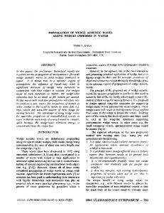
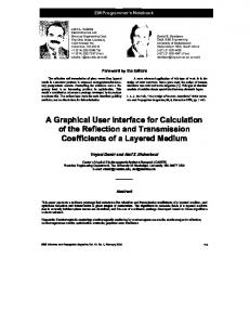
OMPLEX media are of interest to a broad field of applications, ranging from ionospheric research and geophysical exploration, to crystal physics and integrated optics, to microwave and millimeter wave circuitry. Such media are potentially useful, in particular, in developing reciprocal and nonreciprocal microwave and millimeter-wave devices, highefficiency microstrip antennas and arrays, guiding devices and couplers, microwave and photonic lenses, and optical filters. In this paper, we investigate propagation in the general configuration, shown in Fig. 1, of a bianisotropic cylinder (region , of parallel 1), which: 1) encloses an arbitrary number, )] and cylindrical bianisotropic rods [regions ( 2) is embedded in an unbounded bianisotropic space (region 0). If desired, some regions (or all) may either be filled by isotropic or biisotropic (e.g., chiral) media or be occupied by perfect electric conductors (PECs). Although for simplicity all regions are taken to be homogeneous herein, the extension to cylindrically stratified regions is straightforward. Some special cases shown in Fig. 2, independently treated in the past by several methods (separation of variables, coupled mode theory, and finite elements) [1]–[8], serve here to partially test the accuracy and correctness of our numerical codes. The techniques in this paper parallel those of [9], where the corresponding nonhomogeneous (scattering) problem for an obliquely incident plane-wave excitation is addressed. The Manuscript received November 30, 2001. This work was supported by the Institute of Communication and Computer Systems of the National Technical University of Athens (ICSS-NTUA) under the Archimedes 2000–01 Basic Research Project 65/37. The work of I. Vardiambasis was also supported by the State Scholarship Foundation of Greece. The authors are with the Department of Electrical and Computer Engineering, National Technical University of Athens, GR 15773 Athens, Greece. Digital Object Identifier 10.1109/TMTT.2003.808725
Fig. 1. Geometry of the problem: the bianisotropic cylinder (" ; � ; � ; � ), embedded in the unbounded bianisotropic space (" ; � ; � ; � ), encloses the bianisotropic cylinders (" ; � ; � ; � ); i = 2; 3; . . . ; M .
(a)
(b)
(c)
(d)
Fig. 2. (a) Coaxial gyrotropic chirowaveguide. (b) Two coupled parallel chiral rods. (c) Circular chiral/dielectric waveguide. (d) Parallel two-wire line covered with a three-layer dielectric.
analysis in both papers ends up with infinite systems of linear, algebraic equations whose matrix elements assume closed single-term forms. time dependence has been supThe assumed pressed throughout the analysis.
0018-9480/03$17.00 © 2003 IEEE
762
IEEE TRANSACTIONS ON MICROWAVE THEORY AND TECHNIQUES, VOL. 51, NO. 3, MARCH 2003
II. BASIC THEORY Consider a bianisotropic medium characterized by the constitutive relations
Here and denote the roots, with respect to quadratic equation
, of the bi(6)
and (1a)
(7)
is the intrinsic impedance of free space. where Our analysis is restricted to the case where all tensors , , , and have the form1
(1b)
III. REPRESENTATION OF THE FIELD IN REGION (i) denote the field of a mode propaLet and gating in the structure of Fig. 1. We use the notation ( denote the Bessel and the second-kind Hankel functions of order )
dependence of the form , the field inside such a medium can be expressed and , which in terms of its components along the axis, are found to satisfy the coupled second-order differential equations of Assuming
(8) (2) where , , , and and In terms of the field are given by
are constants given in [9, Appendix]. , the transverse (to ) components of
(3) where expressions for the constants , , , , , , , and are given in [9, Appendix]. The general solution of (2) may be written in the form (4)
, is used to designate where the superscript , the region of space and apply separation of variables to obtain ) and (9a)–(9c), shown at the bottom of this page. Here ( ) are unknown expansion constants and ( ) denote ( the polar coordinates of in the coordinate system ( ) associated with the th cylinder. With the help of (9a)–(9c), the other components of the field may be found via (3). Expressions for the field, referring to the coordinate system ) exclusively, can be found from (9) ( )( using the translational-addition relations given by [9, eqs. (15)–(16)]. Then, application of the continuity conditions ) over all cylindrical for the tangential components of ( boundaries involved yields an infinite, homogeneous, linear system of algebraic equations, which can most compactly be written in the form of (10), shown at the bottom of the following is the Kronecker delta, denotes the radius page. Here, of the th cylinder, whereas the 2
where
and
satisfy the Helmholtz equation
and (5)
1Gyro-electric-magnetic (gyrotropic) media, magnetized chiroferrites/chiroplasma, biisotropic (i.e., chiral), and simple (isotropic) media are, among others, some practical cases described by (1a) and (1b).
2 matrices
coincide, respectively, with
and
of [9, eq. (20b)]. The quantities ( ), which relative to , are indicated in Fig. 1. specify the position of The prime in the series over means that the term with is excluded from the summation.
(9a)
(9b) (9c)
VARDIAMBASIS et al.: PROPAGATION OF EM WAVES IN COMPOSITE BIANISOTROPIC CYLINDRICAL STRUCTURES
763
TABLE I
=k VERSUS TRUNCATION SIZE n
FOR THE STRUCTURE OF FIG.
2(d)
Vanishing the determinant of the homogeneous system (10) yields the dispersion equation of the structure. This equation is treated numerically after truncating the size of the matrix to a fiin (9a)–(9c). nite value, i.e., by considering finite values of We note the following. 1) With slight modifications, the above analysis is also ap) is occuplicable when any region ( ). In that case, in order pied by a simple dielectric ( to avoid some indeterminacies encountered in the expres, one has simply to replace by the unit sions of matrix everywhere. 2) Further simplification results when some region, say ) vanishes cylinder (i), is PEC. In such a case, ( only the continuity (vanishing) of the and thus at tangential electric field needs to be accounted for.
IV. NUMERICAL RESULTS AND COMPARISONS A. Convergence of the Algorithm Versus The convergence characteristics of the algorithm are shown is presented versus , the truncation in Table I, where size of the series in (9), for the first four modes of the structure ), region (1) is occupied of Fig. 2(d). Region (0) is air ( ), region (2) is dielectric ( ), by a chiral medium ( and regions (3) and (4) are PECs. The parameter values are: mm, , , , , , , , , and GHz. Apparently, the convergence is very rapid and stable. suffices to obtain the propagation For instance, using constant to within eight significant figures.
0
Fig. 3. (R R )=k versus (R coaxial gyrotropic chirowaveguide.
0 R )=�
for the first five modes of a
B. Dispersion Diagrams—Comparison With Previously Published Data Fig. 3 pertains to the gyrotropic chirowaveguide of Fig. 2(a). , For , and for two values of the chirality parameter, , it shows versus for several modes when ( is the freespace wavelength). As seen, the effect of changing the chirality is appreciable for the dominant (TEM) as well as for the higher and modes, our results are order modes. For the compared with those of [1] and the agreement is excellent. Fig. 4 shows the dispersion diagrams of several modes sup(dash–dotted lines) ported by a single chiral rod of radius and by two coupled parallel rods (solid lines) for the parameter , , , values [see Fig. 2(b)] . In the case of the single rod, our and results are indistinguishable from those of [2]. Noticeably, to any mode (HE-n) of the single-rod guide correspond two HE-n modes of the double-rod guide. In other words, the HE-n modes supported by each rod when it is alone in the unbounded space couple to each other and, as a result, they appear displaced in the presence of the second rod. Fig. 5 contains two families of plots. The first family, dotted curves, show the dispersion characteristics of the first three modes of the chiral/dielectric structure of Fig. 2(c) when , , , , , and . These results are in full agreement with
(10)
764
IEEE TRANSACTIONS ON MICROWAVE THEORY AND TECHNIQUES, VOL. 51, NO. 3, MARCH 2003
Fig. 6. =k versus frequency for several modes of the structure of Fig. 2(d). Fig. 4. =k versus k R. (a) Single chiral rod (dashed–dotted curves). (b) Two coupled parallel rods (solid curves).
Fig. 7. =k versus k R for the first two modes for the structure of two parallel dielectric rods coated by a chiral cylinder. Fig. 5. =k versus k R for the first three modes of a circular waveguide loaded by one (dotted lines) or two coupled parallel chiral rods (solid lines).
those of [3]. Note also that the first two modes, HE-1 and HE-2, have apparently the same cutoff frequency. The second family, solid curves, pertain to the case where a second chiral rod of is placed parallel to and at a distance radius from the axis of the first cylinder; its parameters are , , and . Noticeable is the effect of this second rod on the HE-1 and HE-2 modes, which leads to considerable enhancement of the bandwidth for single-mode propagation. Fig. 6 refers to the multiconductor-multilayered isotropic mm, mm, structure of Fig. 2(d). For mm, mm, , , , and , it shows the dispersion curves of several modes. The , , , and have also modes labeled been treated in [4]. Comparison of our results with those of [4] reveals a perfect agreement. We note also that in validating our algorithm we were able to exactly reproduce, among others, the curves in [1, Figs. 3(a)-(c)], [2, Fig. 4], [3, Figs. 2–5], [4, Figs. 6–8], [5, Figs. 4–6], [6, Figs. 2–3], [8, Figs. 2–3] (not shown).
Finally, the exhaustive comparisons which have been carried out in [9] in connection with the corresponding inhomogeneous (scattering) problem provide an alternative test of the present algorithm as well. (As noted previously, the matrix of the final algebraic system has the same form for both problems). versus for the structure (see the inset) Fig. 7 shows and of two identical dielectric rods having radii , with their axes at a distance , which are coated by an when and open chiral cylinder of radius . The parameters of the chiral medium are where takes on three values, , 0.1, and 0.2. Once again, we observe the radical change of the dispersion characteristics with increasing chirality. Fig. 8 refers to the structure (see the inset) of a pair of parallel perfectly conducting cylinders coated by a magnetized ferrite cylinder. The ferrite has a relative dielectric constant and a tensorial relative permeability
(11)
VARDIAMBASIS et al.: PROPAGATION OF EM WAVES IN COMPOSITE BIANISOTROPIC CYLINDRICAL STRUCTURES
765
(a) Fig. 8. =k versus R for the first two modes of the structure of two parallel conducting rods coated by a ferrite cylinder. (R = 0:6 mm; D = 2:8 mm; f = 21 GHz).
Here
, , , , where is the externally applied bias (DC) magis the intensity of the saturation magnetization, netic field, 10 C Kg. To bring to light the effect of and Wb m and let anisotropy, we assume that take on three values, , 0.5, and 1. Inspection of the pertinent results reveals the possibility to dynamically control the dispersion characteristics of the structure, via a change in the externally applied dc magnetic field. Analogous results are shown in Fig. 9 for a perfectly conducting cylinder of radius , which is eccentrically coated by (chiroferrite) that obeys the a composite cylinder of radius constitutive relations of (12) , whereas is given from (11) with Here Wb m . In Fig. 9(a), we show versus for three ( , 1.5, 2.5) when . As values of leads to decreasing values of . seen, an increase of versus for three values of ( Fig. 9(b) shows ) when . As seen, an increase of the . chirality parameter leads to increasing values of Fig. 10 refers to a cylindrical rod, eccentrically coated by a with parameters chiroferrite cylinder [see (12)] of radius . Here has the form (11) with and Wb m . The core rod of ra); 2) dielectric dius is taken to be: 1) air ( ); 3) a chiral medium ( ( ); or 4) a PEC. In order to shed light on the and nonreciprocal behavior of the structure, both are shown versus , , and being the propagation conand direction, stant of the first mode propagating in the respectively. As seen, the nonreciprocal effect is very strong in all cases. It has been proven in [10] and corroborated in [11] that a is equivalent to narrow, infinitely extending strip of width . Moa perfectly conducting cylindrical rod of radius tivated by this remark, comparisons of our results have been carried out with those of [11, Fig. 4] pertaining to a pair of strips
(b) Fig. 9. =k versus k R for the first two modes of a conducting rod eccentrically coated by a chiroferrite cylinder. (R = 0:25R ; D = 0:5R ). (a) � = 0:005S and
= 0:01; 1:5; 2:5:. (b) = 0:3 and � = 0; 0:001S; 0:002S .
Fig. 10. =k versus k R for the first mode of a rod (dielectric, chiral or perfectly conducting) eccentrically coated by a chiroferrite cylinder. (R = 0:5R ; D = 0:4R ).
coated by a dielectric cylinder. Note that the results in [11] were based on quite different principles (singular-integral-equation methods). The agreement with [11, Fig. 4] was excellent (not shown).
766
IEEE TRANSACTIONS ON MICROWAVE THEORY AND TECHNIQUES, VOL. 51, NO. 3, MARCH 2003
V. CONCLUSION Propagation in composite cylindrical structures, composed from a bianisotropic cylinder embedded in an unbounded bianisotropic space and enclosing an array of parallel bianisotropic rods, has been investigated. To this end, a very flexible separation-of-variables technique has been used to yield linear algebraic systems whose matrix elements are given by pole-free, single-term expressions. The correctness and accuracy of the algorithm has been demonstrated by extensive comparisons with previously published data. Several numerical examples have been presented in order to demonstrate the effect of changing the constitutive parameters on the dispersion characteristics of the structure.
[6] S. F. Mahmoud, “Guided modes on open chirowaveguides,” IEEE Trans. Microwave Theory Tech., vol. 43, pp. 205–209, Jan. 1995. [7] Y. Xu and R. G. Bosisio, “An efficient method for study of general bi-anisotropic waveguides,” IEEE Trans. Microwave Theory Tech., vol. 43, pp. 873–879, Apr. 1995. [8] L. Valor and J. Zapata, “An efficient finite element formulation to analyze waveguides with lossy inhomogeneous bianisotropic materials,” IEEE Trans. Microwave Theory Tech., vol. 44, pp. 291–296, Feb. 1996. [9] K. Konistis and J. L. Tsalamengas, “Plane wave scattering by an array of bianisotropic cylinders enclosed by another one in an unbounded bianisotropic space: Oblique incidence,” J. Elect. Waves Applicat., vol. 11, pp. 1073–1090, 1997. [10] C. M. Butler, “The equivalent radius of a narrow conducting strip,” IEEE Trans. Antennas Propagat., vol. 30, pp. 755–758, Apr. 1982. [11] I. O. Vardiambasis, J. L. Tsalamengas, and J. G. Fikioris, “Hybrid wave propagation in generalized Goubau-type striplines,” Proc. Inst. Elect. Eng.–Microwave Antennas and Propagat., vol. 144, no. 3, pp. 167–171, June 1997.
REFERENCES [1] Y. Wenyan, W. Wenbing, and L. Pao, “Guided electromagnetic waves in gyrotropic chirowaveguides,” IEEE Trans. Microwave Theory Tech., vol. 42, pp. 2156–2163, Nov. 1994. [2] J. A. M. Svedin, “Propagation analysis of chirowaveguides using the finite-element method,” IEEE Trans. Microwave Theory Tech., vol. 38, pp. 1488–1496, Oct. 1990. [3] D. Bacon and T. C. K. Rao, “Propagation modes of a cylindrical waveguide loaded by a coaxial chiral cylinder,” Proc. Inst. Elect. Eng.–Microwave Antennas and Propagat., vol. 145, no. 3, pp. 229–232, June 1998. [4] Y. Kuboyama, T. Shibuya, and R. Sato, “Transmission theory of a parallel-two-wire-transmission-line covered with three layer media,” IEEE Trans. Microwave Theory Tech., vol. 42, pp. 264–271, Feb. 1994. [5] P. G. Cottis, “Propagation in cylindrical guides with gyroelectric core and cladding,” Proc. Inst. Elect. Eng., pt. J, vol. 138, no. 6, pp. 383–388, Dec. 1991.
Ioannis O. Vardiambasis (M’01), photograph and biography not available at the time of publication.
J. L. Tsalamengas (M’87), photograph and biography not available at the time of publication.
Konstantinos Kostogiannis, photograph and biography not available at the time of publication.